Star News


Why does the hard drive activity light blink when no one is at the computer. HDD activity indicator
One of the common computer mods is to replace the standard LEDs on the case with some other ones. However, you will agree, it is too simple. And why not make a kind of VU-indicator of loading the hard drive on several LEDs? Something like a VU-meter on amplifiers.
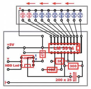
On the above site, a suitable shemka was found:
Everything is simple. Power supply + 5V, on the left in the diagram. At the bottom right, to the outputs of the optocoupler LED (legs 1 and 2), we connect the outputs on the mother, called HDD Led. If you reverse the polarity on this LED, nothing bad will happen, just the LEDs will not light up. But at the input + 5V, it is advisable not to confuse the polarity.
The advantage of such a circuit is that the HDD Led signal from the mother is not directly used by your circuit (the change in the resistance of the emitter-collector junction of the optotransistor in the optocoupler is used). And, therefore, if you connected the mother to the correct optocoupler pins, then no matter how incorrectly your circuit is assembled, it will never damage (read: cover) the mother. :-)
Jumper (jumper) on the diagram determines the mode of operation of the LED scale. If it is closed, then the LEDs light up one after the other from right to left (according to the picture), if it is open, then only one LED will always light up, i.e. you get something like a "jumping point". Because I didn’t like the last option, so I made the circuit without a jumper (I just closed this section).
So, let's look ... What we need for this:
- LM3914 itself, in fact, is a mikruha that controls LEDs (led bargraph driver chip);
- 4N25 (or 4N26, or 4N28 or TIL111) - optocoupler (optoisolator);
- Electrolytic capacitor: 220uF at 25V (we take a voltage margin);
- Resistors (one each): 3.3KΩ, 10KΩ, 470Ω, 330Ω, all at 0.25W.
- LEDs for 2.5-3.5V - 10pcs, cool - multi-colored.
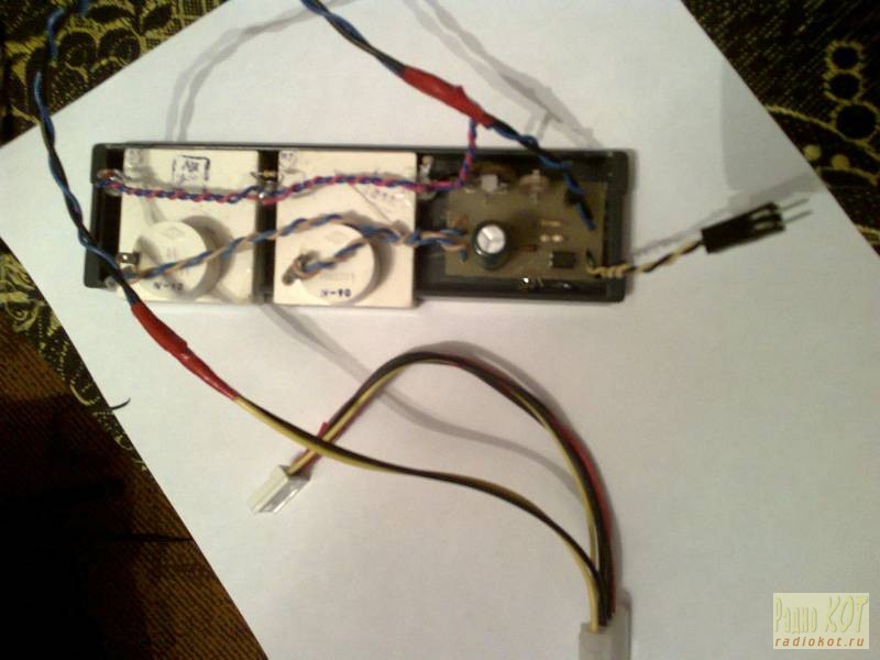
Because I found the diagram on an import site, then at first I decided to assemble everything on cardboard and wires to check the performance, check it out:
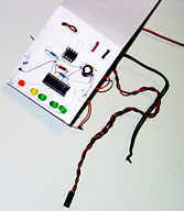
For test purposes, it was too lazy to solder all 10 LEDs, so only five leads from the main mikruha were used. If I checked - it worked, you can skip this step :-).
For ease of connection, you can also stock up on the following components:
- Colored wires (black and red) for connecting to mother and power supply;
- Molex connector for connecting to a standard PSU; you can buy 2 (father and mother for fastening to a wire) and make another coupler if there are no free connectors on the PSU;
- Thin wires, a cable, or a block with screws on a board for connecting LEDs;
- Beds for microcircuits (for 18 and 6 legs) - I highly recommend;
- What you will solder the whole thing on: circuit board, foil textolite / getinaks, cardboard (ghetto-mod :-)).

In principle, you can make it more compact, but my task was not like that. Don't forget the mounting holes in the board if you need them!
I made the payment in the following way. I didn’t want to get involved with ferric chloride, varnish and solvent, so I glued a board printed on paper in a 1: 1 format with an adhesive pencil onto the textolite on the side of the foil (you shouldn’t laugh, it [glue stick] is easy to use, provides good adhesion of paper to foil and , at the same time, the paper can then be easily torn off without the use of additional tools). Just drilled holes in it. I tore off the paper from the foil, connected the necessary holes with a pencil according to the layout of the board, and cut out the tracks with a knife. Holes for power wires can be made with a diameter of about 1.5mm if you are going to use standard wires from the PSU (I did this, taking them from the old PSU).
In general, there is nothing complicated here, but you need to very carefully solder the narrow paths that go from the mikruha to the LEDs, because. there are a lot of them and you can't make them thick. Although I soldered enough at one time, it was still not very easy ... The main thing is that after cutting it is good to clean and degrease the board before soldering. The better you clean / degrease, the easier it will be for the tin to stick to the foil and the less chance it will come off the board. It is better to solder immediately after stripping, and, moreover, all the elements at once, without postponing the next day, otherwise, if you solder half today and, without processing the board in any way, leave it for a week, then you will have to hemorrhoids to clean the sites again or warm up more with flux, from which, most likely, the tracks will come unstuck.
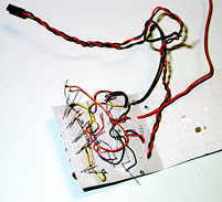
That's what I did:
I decided not to mess with a bunch of LEDs and installed a set of ten LEDs in one package, connecting it to the board with an 11-wire cable, cutting off the cable from the drive accordingly. I soldered the cable directly into the board, but only then the thought occurred to me that it was necessary to install a connector there.
I highly recommend using cribs for microchips. Firstly, you won’t overheat when soldering to the board (the mikrukhs are inserted last), and secondly, if you find a mikrukh with a manufacturing defect (not working, in short), you can easily change it in the store where you bought it, and you can solder it will not be replaced.

When you have soldered the whole thing, you can check the performance as follows:
- When the power is turned on, none of the LEDs should be lit;
- If you close contacts 4 and 5 of the optocoupler (those that go into the circuit), then all the LEDs should light up (or only the last one, if you assembled a circuit with a gap instead of a jumper).
If everything works, you can experiment, for example, with the order of connecting the LEDs, for example, so that the even ones in the row light up first, and then the odd ones, etc.
Analog indicator of hard drive loading
For fans of analog technology, you can offer this option:
Those. instead of a circuit and LEDs, you can connect some existing dial indicator with a decent internal resistance, for example, from some kind of tape recorder. Set the current limit with a potentiometer. We connect to the HDD-Led connector on the mother. Unlike the previous version, here, if you take a device that is too powerful and not very sensitive (with low internal resistance), you can easily damage the motherboard and then you will not have any indicator of HDD operation.
Introduction
The loading indicators, which will be discussed, are not only an improvement in appearance, but also have a purely practical benefit.
This article consists of two independent parts: CPU and hard drive loading indicator.
Hard drive loading indicator
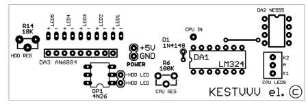
Before starting to create the indicator, I decided to look for the most optimal scheme. Scrolling through a number of sites, I found a relatively small variety of schemes. One of the most important criteria is to get a high-quality mod for relatively little money. Most circuits use LM3914 chips, which are not that cheap. Therefore, I began to look for a level indicator chip with an output for 5-8 LEDs. The choice fell on the AN6884 because of its low price and wide availability. This microcircuit has five LEDs at the output, and passes through each current 7mA.
To read the signal, two wires coming from the motherboard are used, to which the hard drive indication LED located on the front panel is connected. Instead of an LED, an optocoupler input is connected to them (see diagram). Even if you reverse the polarity, nothing will burn. The optocoupler in the diagram is necessary for the electrical decoupling of the circuits of the motherboard and the indicator (this is primarily necessary to protect the motherboard).
At zero load - the phototransistor inside the optocoupler is locked - while C6 is discharged through R11. With an increase in the loading of the hard drive, the phototransistor is open, and C6 begins to charge through it. The voltage at C6 varies in proportion to the load level. Depending on the capacity of C6, the rate of change in the load level changes.
The voltage from C6 is removed through the divider R12, R14. Trimmer resistor R14 is used to change the sensitivity of the indicator.
LEDs can be installed any and at your discretion. At home, I set for the three smaller levels - green, and for the two large ones - red.
Hard drive indicator circuit
Setting the indicator is reduced to setting its sensitivity using R14.
CPU load indicator
When the hard drive indicator was already made, I began to think about an indicator of something else. The choice fell on the processor load indicator.
During the search, two options were found - through LPT and through COM.
I chose the COM port only because it was not used, unlike LPT. In the process of searching, I found an article by Clear66, in which he talked about connecting a car tachometer to a COM port. I liked this idea most of all because you do not need to make special circuits for converting digital values to an analog signal. For control, the PCTach program is used (download link is at the end of the article).
But since at that moment there was not at least some kind of tachometer at hand, I had to make a home-made version of the factory one. After assembly and configuration, the processor load indicator began to show more or less accurately.
But I did not like the increased speed of displaying the load level, which was expressed by excessive jerking of the indicator arrow during uneven processor load. But this was corrected by adding an additional capacitor in parallel with the microammeter.
The type of dial indicator did not suit me much, and I decided to look for an alternative to it. In the end, the indicator became LED, and not a scale of LEDs, but two LEDs of different glow colors directed towards each other. The load level is displayed by smoothly changing the brightness of the LEDs.
For the manufacture of the indicator, I used 4-5mm plexiglass and two LEDs: red and blue glow. A strip of 150mm by 15mm is cut out of plexiglass. After that, places for LEDs are cut out along the edges of the strip. The ends and one side of the strip must be sanded with zero sandpaper to a uniform matte state. This is necessary for uniform dispersion of light. A strip of foil is glued to the reverse side (which is not processed with sandpaper) and on the sides of the strip to reflect the rays of the LEDs. When the strip is ready, the LEDs are glued.
Arrangement of LEDs in a Plexiglas strip
When the LEDs are already glued, tape or self-adhesive film is glued to the ends of the strip. This is necessary so that the LEDs shine only in the desired part of the strip.
Blue on top symbolizes cold, i.e. low CPU usage. Red at the bottom symbolizes heating, i.e. big load. The processor load is proportional to the transition of colors between themselves. The wires going to the board and the 68-100 Ohm resistor are fixed from one edge of the strip with hot glue.
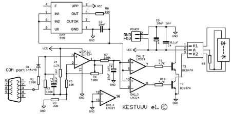
To smoothly change the brightness of the LEDs, a PWM signal generation circuit is used. With this control method, the brightness of the LEDs varies from the ratio of the glow time and the time when it is off. This method is better than voltage control in that the brightness of the LEDs changes in proportion to the voltage.
The scheme consists of the following blocks:
voltage driver on DA1.1
sawtooth signal generator on DA2
voltage comparison unit on DA1.2 DA1.3
The resistor divider R4,R3 sets the voltage to 1.2 volts, which is approximately equal to the minimum sawtooth pulse voltage DA2. Pulses are taken from the third output of the computer's COM port. When the input level is high, capacitor C1 charges through resistor R1 and diode D1. When the input level is low, capacitor C1 discharges through R2. On C1, a voltage is formed proportional to the processor load level. Since the amplitude of this voltage is less than the amplitude of the sawtooth pulses DA2, there is an amplifier on DA1.1 in the circuit. The maximum level of the indicator is adjusted by changing the gain using R6. The R7, C3 chain finally smooths out the voltage ripple from the amplifier output. PWM is formed by comparing the measured voltage and sawtooth pulses.
DA1.2 generates a direct, and DA1.3 an inverted PWM signal. These two signals are then fed to the LEDs, previously amplified by switches on transistors T3, T4.
Processor indicator circuit
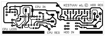
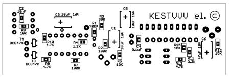
Execution
Since both indicators are located on the front panel, I made a common board for them. From one edge of the board there are two tracks in the form of strips. Two M3 nuts are soldered to these strips. At the front, two 3mm holes are drilled in the case frame so that they correspond to the distance between the centers of the nuts on the board. Further, two M3 screws are screwed into these nuts on the board, which pass through the holes in the frame.
CPU load indicator with different load levels:

But really, there's probably nothing to worry about. Computers with default Windows settings do this all the time. Although, of course, the possibility of infection cannot be ruled out, so it will not hurt to check the system with an antivirus for your own peace of mind.
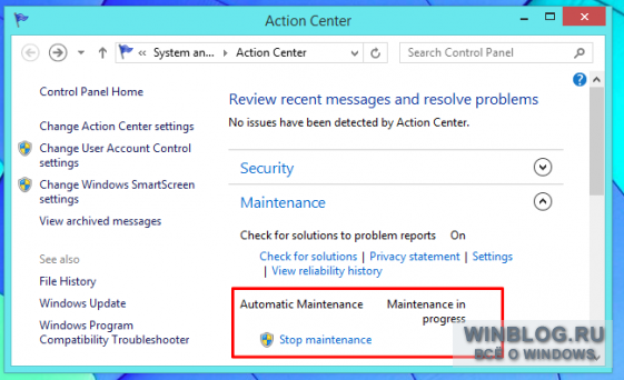
The computer politely waits for its turn
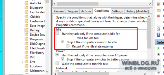
In fact, the computer does not try to do nasty things secretly from the owner. On the contrary, he tries to be smart and polite. Windows needs to run a variety of service tasks in the background, and the system patiently waits for idle time (that is, the user leaves) to run them. This ensures that computer resources are not wasted on extraneous matters when the user needs them to work. If the system is being actively used, background housekeeping processes are suspended so as not to degrade performance.
So it's not a figment of the imagination: Windows is really waiting for idle time to start maintenance. And when the user comes back, service tasks usually stop, so it's usually impossible to figure out why the hard disk activity indicator blinked when idle. The Windows Scheduler gives you the ability to set the task to run exclusively during idle times, and many tasks are performed this way.
What is the computer doing when idle?
But what exactly is the computer doing in the background? The specific set of tasks depends on the system settings and installed programs, but the most common options can be listed.
File indexing. All modern operating systems are equipped with a file indexing function. They check each file (including its contents) and create a database that then instantly returns results when searched. For search to work, the indexing service must regularly check for file changes, and this may explain hard disk activity when idle.
Disk Defragmenter. In the days of Windows 98, you had to close all other programs to successfully defragment your hard drive. Modern versions of Windows defrag automatically in the background, but only when idle.
Scheduled antivirus scanning. Many antivirus programs and other security tools are set by default to automatically scan your system on a regular basis. Perhaps the activity of the hard drive is due to the fact that the antivirus is just checking the files stored on it.
Backup. If automatic backup is enabled (and it should be enabled!), hard disk activity may be caused by the file backup process.
Automatic update. Windows itself and many programs such as Google Chrome or Mozilla Firefox have an automatic update feature. If the computer is busy with something when idle, it is quite possible that it is just downloading and installing updates.
Of course, this is by no means full list. There can be an infinite number of options, depending on the specific set of installed programs. For example, if the Steam client is open in the background and an update has just been released for one of the games, the hard disk activity may be due to the download and installation of this update. File download programs, such as BitTorrent clients, can also cause disk activity.
How to find out what programs are using the disk when idle
In theory, everything is clear, but how to find out what the computer does in practice? First of all, if there is a suspicion of infection, it is worth scanning the system with a reliable antivirus, not relying solely on built-in tools. But if you just want to track disk activity, you can do that too.
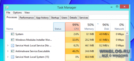
You can find out which processes are using the disk using the Task Manager and Resource Monitor built into Windows. This is especially true if the disk activity indicator is constantly blinking, and the computer's performance has dropped for some reason.
To open the Task Manager, right-click on the taskbar and select Task Manager or press the ++ keys. In Windows 8, disk usage is displayed right in the Task Manager - you can click on the "Disk" column to sort processes by this parameter and see which one uses the disk the most.
Windows 7 does not have this option, so you need to open the Performance tab and click the Open Resource Monitor link. In the Resource Monitor window, go to the "Disk" tab - and you will see a list of processes that can be sorted by the degree of disk load. By the way, in Windows 8 / 8.1, the Resource Monitor also gives much more information than the Task Manager.

To track disk activity over time, you can use the Process Monitor program from SysInternals, a developer of useful utilities that advanced Windows users love so much. You can start Process Monitor and leave it running during downtime. Then, returning to the computer, you can see which processes used the hard drive in your absence.
Process Monitor logs any activity, but you can use the buttons on the panel to filter the list so that only events related to file system. For example, in the screenshot below, you can see that disk activity is caused by file indexing.
Process Monitor is good because it can show past activity. Even if a process stops using the disk or terminates altogether, information about it remains in the log. But it is hardly worth using this utility all the time, because event logging also creates a load on the system and, as a result, reduces performance. It should also be understood that Process Monitor keeps an event log only while it is running: if you start it after a surge in hard disk activity, it will no longer be possible to find out what exactly caused it.
Many have long dreamed of doing something like that with their computer (paint, highlight, cut through the window :-)). And everyone wants everything to turn out beautifully, simply and, most importantly, safely - after all, it is fear that usually repels beginners from thinking about modding their camper! In this article, I would like to offer you ALL IN ONE! The mod that I will describe is simple and almost absolutely safe to implement and, importantly, the beauty and functionality will simply amaze everyone around you and will undoubtedly increase your rating. And I want to talk about the hard drive loading indicator, or to be more precise, about its modernization. So, while looking at various MODs on thematic sites, I somehow came across a fairly simple and effective home-made device for a PC - an HDD loading indicator.
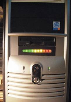
100% of computers are equipped with a conventional hard drive operation indicator based on a single LED. I propose to expand the possibilities and add spectacularity to the usual at first glance indicator of HDD loading. The indicator option discussed below will no longer consist of one, but of 10 LEDs! Interested? Then we move on...
Principle of operation
As you know, a lot of wires stretch from the motherboard towards the front panel of the PC (power indicator, hard drive loading, reset, on / off, etc.) For more information regarding the location and number of wires, as well as their polarity, I strongly recommend that you look into mom manual!!! In our case, we will be interested in two contacts on the board, signed H.D.D. and LED (Fig. 1a) (depending on the motherboard model).
It is from them that our future indicator will receive data. Currently connected to them is a simple LED on the front of your case. When the system accesses the hard drive, the power to the LED begins to pulsate. If the indicator just glows, the propeller is fully loaded; if it flickers, it is approximately half loaded, etc. Agree, it is somewhat inconvenient, especially for advanced users :-). We will significantly improve the proposed default display system and instead of flickering we will use a number of LEDs up to 10 pcs. The point is that now the degree of access to the hard drive will be determined not by one, but by ten LEDs lined up (Fig. 2).
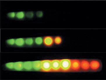
In principle, no one forbids placing them in any form convenient for you, and the shape of the indicator is limited only by your imagination. The LEDs will light up in turn (you choose the direction yourself), creating the effect of a jumping column. Our indicator will have two modes of operation: 1) the LEDs light up in turn, and when fully loaded, the entire row lights up; 2) the LEDs light up one by one, that is, instead of a column, a jumping dot is obtained. The device will be powered by 5V, refined, of course, in our PSU. Well, here are the pies :-), let's start assembling ...
Ingredients
For complete happiness, we need the following ingredients:
chip - LM3914(a);
four resistors - 3.3 kΩ, 10 kΩ, 470 ohm, 330 ohm (all at 0.25 W);
capacitor - 220 uF at 25V (not necessarily 25V, but not less, but the capacitance will affect the reaction speed of the indicator);
optocoupler - 4N2x (4N25, 4N26, 4N28 or TIL111);
ten LEDs (preferably super-bright and different colors, experience has shown that two are better: 7–8 of one and 3–2 of the other);
two panels: for 18 and 6 legs (required to protect the microcircuit and optocoupler from possible overheating with a soldering iron);
mini-switch, jumper (to select the indicator mode);
molex MAMA (Fig. 1b) (we need only two contacts: red and black, it is better to cut off the rest);
connector for connecting the indicator to the mother (Fig. 1a) (cut off from the old indicator);
10-wire cable with connectors MALE, MAMA (Exclusively for the convenience of connection, so as not to mess with separate wires);
frame;
textolite, ferric chloride, flux, tin, rosin, nail polish :-), connecting wires about 50 cm (standard set of a young soldering iron lover :-));
Pryamyje Ruki - 2 pcs. (Without this, the assembly does not start!)
All of the above is easily found on the local radio market, except for the last item.
The most expensive element is mikruha - about 6-8 UAH, the rest is 0.3-2 UAH.
I think you can buy a dead flopik there without any problems. As for textolite and ferric chloride: there is an opportunity and a desire - be sure to buy it (about 10 UAH), otherwise you will have to suffer with cardboard and wires! Personally, for verification, I first assembled it on cardboard, and only then I bought textolite. In principle, it makes no sense for you to do this, since it has been checked - there are no viruses :-)!
Assembly
It is simply not possible to describe drawing, drilling, etching and soldering in this article, we will proceed from the fact that you already know all this or you can ask someone. The diagram of our indicator is shown in fig. 3 (from the side of the legs).
First, carefully solder all the necessary components (Fig. 4).
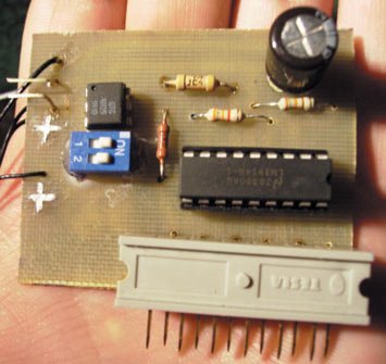
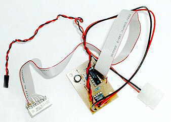
After that, you need to decide where the main indicator board will be located, since the length of the wires to the motherboard, power supply and cable to the LEDs will depend on this! Personally, I used the old floppy drive (3.5") (Fig. 5).
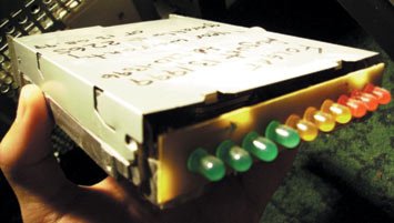
Having pulled out all the stuffing and removed the front panel, we get an excellent case for our device. The advantage of this solution is that such a case is very easy to fix inside the system unit, the minus is that it is completely metal, and this is fraught with interaction with the 5V power supply from the PSU! That's exactly why we need varnish - to cover the surface of the board and isolate it from the metal case, to be sure, you can pack it in a small plastic or plastic bag. Of course, in the absence of an old drive, you can use something else (anyhow it fit into the system unit :-)), or, at your own peril and risk, fix the board without a case (100% isolation!) Since my whole circuit was located in close proximity to LEDs, the cable length was about 10 cm, power wires - no more than 5 cm (two pairs of wires come from the molex: 12V and 5V-red and black, we need the latter (Fig. 1b)), to the motherboard - about 20 see Now we solder the pre-measured wires. The indicator is ready! To check, it is necessary to close contacts 1 and 2 of the optocoupler, if everything is assembled correctly, then the entire chain of LEDs will light up or only the last one (depending on the state of the jumper). If, when connected to a PC, nothing works the first time, we try to turn the HDD LED connector on the mother (it will not get worse). I attached the board with LEDs to the drive with hot glue. My indicator is located in the 3.5" bay below the drive, where I specially cut out an oval window in the stub and covered it with transparent plastic from the CD box (Fig. 6).
That's basically it. With a small investment of time and money, we get a pretty good effective indicator of HDD loading. .
Dial indicator HDD
Probably everyone is familiar with dial indicators from tape recorders, for example, these. Yes, a reel-to-reel tape recorder, Vysotsky's recordings ... Well, okay, we're not talking about that, but about how to attach these very indicators to the miracle of modern technology - a computer, as an indicator of hard disk access. That is, we will replace the nondescript blinking diode on the front panel, yes, yes, the same one.
It is worth saying that such schemes are found on the Internet, but for two indicators at once - I have not seen anything like this.
Here is the diagram itself:
As you can see, nothing supernatural. The whole point is that one indicator shows the instant loading of the HDD, that is, at a given second, and the other is the average value for some time, this time is determined by the electrolytic capacitor. The diode prevents the capacitor from discharging to the "fast" indicator. The pc817 optocoupler can be torn out of the old power supply, wires are connected to it, going from the motherboard to the old diode, which we mercilessly solder. The transistor is also the first one that came to hand - c945. The circuit is powered by + 12V bus. Resistor ratings are approximate, because most likely you will have to select them for your indicators, transistor and optocoupler.
Setting. Resistor R4 sets the maximum deviation of the arrows. With the help of R3, we compensate for the voltage drop across the diode, i.e. "align" the readings of PA1 and PA2.
I decided to arrange the whole thing in one of the plugs on the front panel. We will fix it with glue Moment Crystal, which is transparent.

Also, the diagram does not indicate three white backlight LEDs, but this is already individual, perhaps small incandescent bulbs will look more organic for you (at first it was intended).
It remains only to connect everything (of course, with the computer turned off), turn on the computer and adjust the readings with resistors R3 and R4.
Video work of this device when copying files from partition to partition.