Star News


Powerful power supply for lm317 and kt827. LM317 and LM317T wiring diagrams, datasheet
It is quite easy to make a power supply that has a stable output voltage and regulation from 0 to 28V. The base is cheap, reinforced with two 2N3055 transistors. In such a circuit connection, it becomes more than 2 times more powerful. You can, if necessary, use this design to get 20 amps (almost without alterations, but with the appropriate transformer and a huge heatsink with a fan), just did not need such a large current in your project. Once again, make sure you mount the transistors on a large heatsink, 2N3055s can get very hot under full load.
List of parts used in the scheme:
Transformer 2 x 15 volt 10 amp
D1...D4 = four MR750 (MR7510) diodes or 2 x 4 1N5401 (1N5408).
F1 = 1 amp
F2 = 10 amps
R1 2k2 2.5 watts
R3,R4 0.1 ohm 10 watt
R9 47 0.5 watt
C2 two times 4700uF/50v
C3,C5 10uF/50v
D5 1N4148, 1N4448, 1N4151
D11 LED
D7, D8, D9 1N4001
Two transistors 2N3055
P2 47 or 220 ohm 1 watt
P3 10k Trimmer
Although LM317 and has protection against short circuit, overload and overheating, the fuses in the transformer network circuit and the F2 fuse at the output will not interfere. Rectified voltage: 30 x 1.41 = 42.30 volts measured at C1. So all capacitors must be rated at 50 volts. Attention: 42 volts is the voltage that can be output if one of the transistors is broken!
Regulator P1 allows you to change the output voltage to any value between 0 and 28 volts. Since in LM317 the minimum voltage is 1.2 volts, then in order to get zero voltage at the output of the PSU - put 3 diodes, D7, D8 and D9 at the output LM317 to base 2N3055 transistors. At the microcircuit LM317 the maximum output voltage is 30 volts, but using diodes D7, D8 and D9, on the contrary, the output voltage will drop, and it will be about 30 - (3x0.6V) = 28.2 volts. You need to calibrate the built-in voltmeter using the P3 trimmer and, of course, a good digital voltmeter.
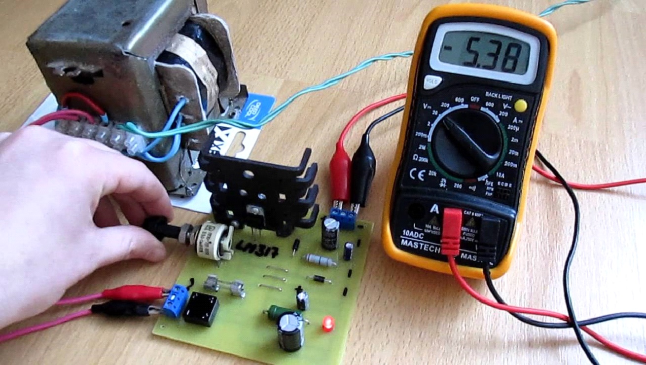
Note . Remember to isolate the transistors from the chassis! This is done with insulating and thermally conductive pads, or at least thin mica. You can use hot glue and thermal paste. When assembling a powerful regulated power supply, remember to use thick connecting wires that are suitable for transmission high current. Thin wires will heat up and melt! Power Supply - this is an indispensable attribute in the workshop of a radio amateur. I also decided to build myself an adjustable PSU, because I got tired of buying batteries every time or using random adapters. Here it is a brief description of: The PSU regulates the output voltage from 1.2 Volts to 28 Volts. And it provides a load of up to 3 A (depending on the transformer), which is most often enough to test the performance of amateur radio structures. The circuit is simple, just for a beginner radio amateur. Assembled on the basis of cheap components - LM317 and KT819G.
LM317 Regulated Power Supply Diagram
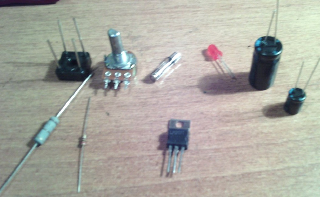
List of circuit elements:
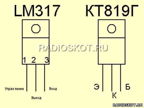
- Stabilizer LM317
- T1 - transistor KT819G
- Tr1 - power transformer
- F1 - fuse 0.5A 250V
- Br1 - diode bridge
- D1 - diode 1N5400
- LED1 - LED of any color
- C1 - electrolytic capacitor 3300 microfarad * 43V
- C2 - ceramic capacitor 0.1 microfarad
- C3 - electrolytic capacitor 1 microfarad * 43V
- R1 - resistance 18K
- R2 - resistance 220 Ohm
- R3 - resistance 0.1 Ohm * 2W
- P1 - building resistance 4.7K
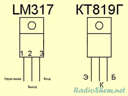
Pinout of the microcircuit and transistor
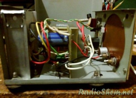
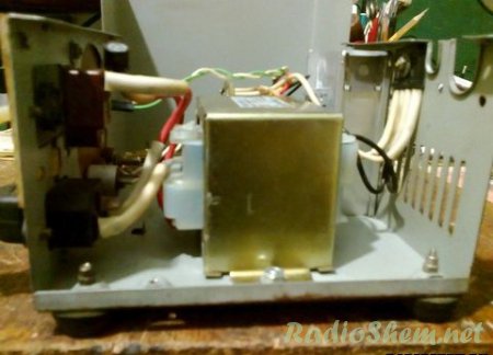
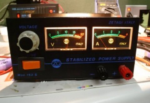
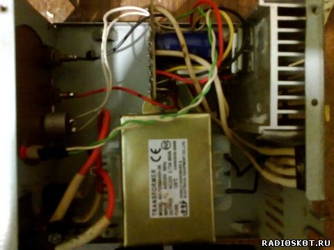
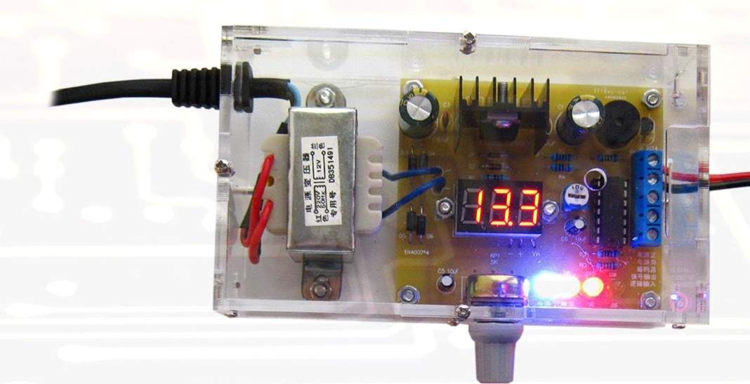
The case was taken from the computer's power supply. The front panel is made of textolite, it is desirable to install a voltmeter on this panel. I haven't installed it because I haven't found the right one yet. I also installed clips for output wires on the front panel.
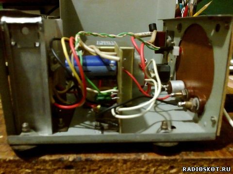
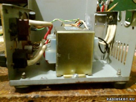
The input outlet was left to power the PSU itself. A printed circuit board made for surface mounting of a transistor and a stabilizer microcircuit. I fixed them on a common radiator through a rubber gasket. The radiator took a solid one (you can see it in the photo). It should be taken as large as possible - for good cooling. Still, 3 amps is a lot!
Today, when new technologies and electrical appliances appear almost every year, it is very difficult to do without some equipment at home. A particularly important role in our lives is given to power supplies. Any radio amateur should be able to assemble this device with his own hands.
In today's article, we will talk about how to make such an important electrical appliance in the home laboratory as the lm317 power supply. The scope of such equipment is huge, so the knowledge of how to assemble it with your own hands will be relevant and useful in everyday life.
Device Features
The power supply is an important attribute of any amateur radio home workshop. The principle of operation of the power supply is that it can convert the voltage and current in the network to the parameter we need for powering and connecting various electrical appliances. At the same time, such a device provides high protection against short circuits.
The power supply can be of two different types:
- adjustable;
- impulse.
In addition, the scheme that is used to assemble this type of power supply can be different - from the simplest to the most complex.
Note! If you are new to radio electronics, then first you should choose simple circuits. Such a scheme will be clear to you and will allow you to quickly create a device for a wide variety of needs.
Approximate scheme
The decision to assemble a power supply on an lm317 chip greatly simplifies the assembly process. At the same time, the circuit itself is also simplified. Thanks to the microcircuit, it becomes possible to make a regulated power supply and provide power stabilization.
If you believe the comments left by radio amateurs, such an assembly is several times superior to domestic counterparts, while possessing large resources.
Principle of operation
Now let's consider the principle of operation of the device, since when assembling a lm317 type power supply in order to be able to regulate the voltage indicator, as well as the current strength in the network, it is necessary to clearly know and understand this aspect. Without this, it is impossible to properly assemble the device, even if the circuit is quite simple.
Working PSU
The power supply type lm317 is characterized by the following principle of operation. The lm317 microcircuit is engaged in regulating the current strength at the output and contributes to the voltage drop. The voltage drop occurs across the resistor. The resistor across which the voltage drops occurs has a value of 1.25 V.
As a result, such a circuit allows, by changing the value of the resistor, to adjust the voltage and provide a change in the current strength indicator.
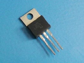
Chip
Note! If the soldering of the parts was carried out correctly, then such a device prevents the occurrence of a short circuit. Here, the quality of the parts themselves plays an important role in the assembly. Therefore, give preference to better products by buying them from trusted sellers.
In addition, it must be remembered that this scheme for assembling a power supply with the participation of the lm317 chip has some limitations. The lower limit limit is 0.8 ohm and the upper limit is 120 ohm. Thus, for the selection of a resistor in order for this circuit to function normally, one must be guided by the formula 0.8 The lm317 type power supply can be used to change the voltage and current parameter in the following situations: Note! Most often, the power supply is used in tandem with an LED strip. Thanks to this, you can get high-quality lighting in any room of the house. In this case, protection against short circuit will be at a sufficiently high level. Backlight This is a basic, but far from complete list of all situations in which you may need the help of a lm317 power supply. Assembled on the basis of the lm317 chip, the power supply has the following characteristics: Note! Such a load is quite enough to check the performance of home-made electrical structures. At the same time, the circuit used in this case will be quite simple and will allow a person with minimal knowledge of radio electronics to assemble the required device. It includes cheap and common parts that can be easily found on the market or in specialized stores. Approximate set of parts If you want to create an adjustable type of power supply on the lm317 chip to change the voltage and current parameter, you will need the following parts: It is worth noting that, depending on which scheme is planned to be used to assemble such a block, the possible list of parts required in the work will also change. Transformer Before we start assembling the lm317 adjustable type short circuit protected unit, it is necessary to buy all the parts and components required for the job. Here it must be remembered that the service life and quality of work of the assembled PSU will directly depend on the quality of the purchased radio engineering products. This part can be removed from any electrical appliance that is idle at home or has already broken. For example, a transformer can be removed from a TV, tape recorder, etc. Power transformer Some recommend including a TVK-110 brand transformer in the circuit. It was previously installed in black-and-white TVs in a frame scan unit. But there is one minus here - the output voltage here will be only 9 V, and the current strength will be small. Moreover, if you need to power a powerful electrical appliance, then this transformer will not cope with the load placed on it. At the same time, remember that their power should be at least 40 watts. To make a PSU on an lm317t micro-assembly for a DAC, you will need an output voltage in the range of 3.5-5 V. This is the voltage level that should be maintained in the circuit to power the microcontroller. After you have chosen the assembly scheme and acquired all the necessary components, you can get to work. As already mentioned, in our case, the assembly of an adjustable type power supply will be based on the lm317 chip. Note! The rectification type can be full-wave, single-half-wave, tripling, doubling, bridge. For a conventional PSU, it is better to take a bridge type of rectification. Rectifier circuit diagram Voltage stabilizer circuit Ready-made PSU option After that, we are guided by the chosen scheme, installing the remaining parts. As you can see, with a properly selected circuit, depending on your level of professionalism and knowledge of radio engineering, you can easily create an adjustable-type power supply based on the lm317 chip with your own hands. In order for you to succeed, you need to follow the assembly scheme, as well as purchase quality parts. As a result, you will get an excellent power supply with excellent characteristics - an indispensable assistant in the home laboratory of any radio amateur.
Power Supply- this is an indispensable attribute in the workshop of a radio amateur. I also decided to build myself an adjustable PSU, because I got tired of buying batteries every time or using random adapters. Here is its brief description: The PSU regulates the output voltage from 1.2 Volts to 28 Volts. And it provides a load of up to 3 A (depending on the transformer), which is most often enough to test the performance of amateur radio designs. The circuit is simple, just for a beginner radio amateur. Assembled on the basis of cheap components - LM317 and KT819G. LM317 Regulated Power Supply Diagram List of circuit elements: Pinout of the microcircuit and transistor The case was taken from the computer's power supply. The front panel is made of textolite, it is desirable to install a voltmeter on this panel. I haven't installed it because I haven't found the right one yet. I also installed clips for output wires on the front panel. The input outlet was left to power the PSU itself. A printed circuit board made for surface mounting of a transistor and a stabilizer microcircuit. I fixed them on a common radiator through a rubber gasket. The radiator took a solid one (you can see it in the photo). It should be taken as large as possible - for good cooling. Still, 3 amps is a lot!Application area

The power supply, powered by the lm317 chip, will allow you to stop using random adapters, as well as periodically buy batteries.Device characteristics
Getting ready to assemble
![]()
Therefore, if you are not very well versed in components, it is best to buy only where you can be provided with a quality certificate for the products sold.
One of the most important parts in any assembly scheme will be the transformer. It is used to step down the voltage as a converter.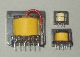
Here, if there is a need for a powerful PSU, power transformers should be used.
You may also need minor changes to the secondary without affecting the primary.Assembling the power supply
The assembly goes like this: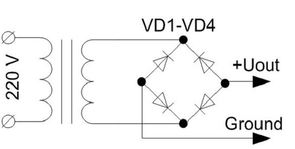
![]()
All elements of the circuit can be placed in a case, for which plastic or aluminum sheet should be used. But you can give the PSU absolutely any shape that you yourself want. How to choose and install volume sensors for automatic light control
Stabilizer LM317
T1 - transistor KT819G
Tr1 - power transformer
F1 - fuse 0.5A 250V
Br1 - diode bridge
D1 - diode 1N5400
LED1 - LED of any color
C1 - electrolytic capacitor 3300 microfarad * 43V
C2 - ceramic capacitor 0.1 microfarad
C3 - electrolytic capacitor 1 microfarad * 43V
R1 - resistance 18K
R2 - resistance 220 Ohm
R3 - resistance 0.1 Ohm * 2W
P1 - building resistance 4.7K