Star News


Scheme of connecting light to the switch. How to connect a switch with one key: detailed instructions
Before buying and installing a two-gang switch, you first need to decide what it is for at all? And it is intended to control two lighting circuits from one point.
Do not confuse it with pass-through switches, which play other roles. They differ from each other in the number of contacts. Therefore, when choosing, look first of all not at the front panel, but at the back of the switch.

two-gang light switch

two-gang simple switch
Let's say if you have 2 or more light bulbs in the chandelier, using a two-gang switch, you can make it so that when you press one key, only half of the lamps turn on, and when you press the second, all the rest at once. 
It can also be controlled by two different lamps located at separate points from each other - for example, lighting sconces at different ends of the room or in another room altogether. 
A two-key switch differs from its one-key counterpart not only in the number of switches, but most importantly, in the number of contacts. There are only 3 of them here. One common and two outgoing. Through them, the phase is separated and then returned to the junction box by separate wires or goes directly to the fixtures.

Note that you will need at least a three-wire wire to install a double switch, even if you do not have a PE protective earth conductor in your apartment wiring. 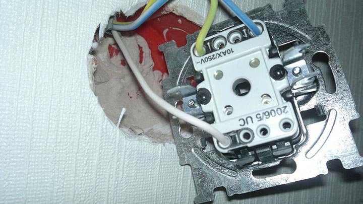
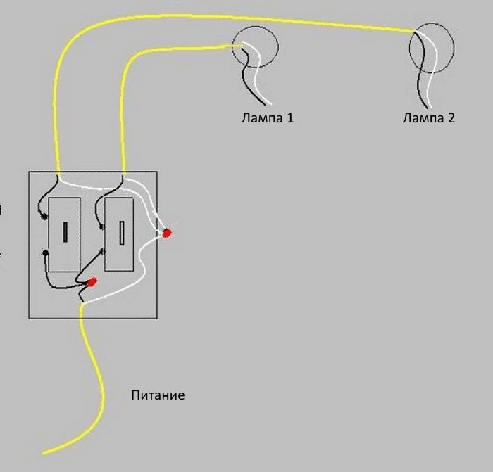
Installation of a two-gang light switch and wire connection
There is nothing complicated in the connection diagram and in the process of installation, installation and connection of wires to the switch contacts. First of all, the switch must be disassembled. To do this, dismantle the keys themselves. If you can’t do it manually, simply by pulling them towards you, use an ordinary screwdriver, prying the keys from the side. 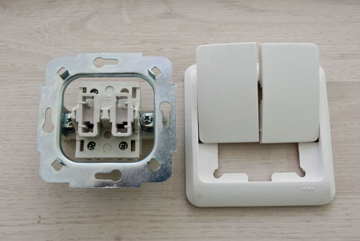
As a result, you have the body itself with fasteners on the sides and the inner contact part in your hands. The main task is to supply voltage from the phase conductor to the common contact. Further, when two keys are closed, this phase will diverge to one or the other lighting circuit. 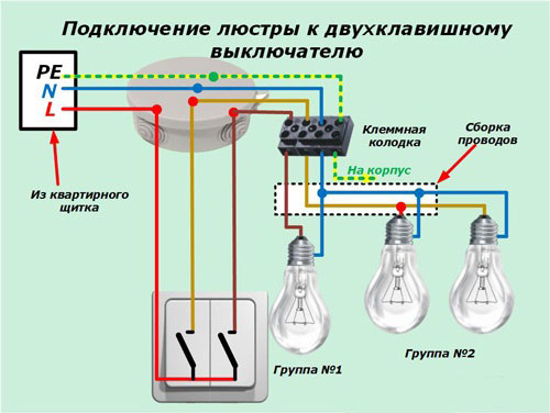
To find the central contact, look at the marking, since it may not always be located exactly alone and in the center. 
But what if you do not understand the inscriptions or they are erased and painted over? Then you need to use a contact screwdriver with a tester with a battery-powered dialing function.
Insert any metal object (stud, screw) into the intended common contact. You wrap your fingers around it, and touch the other two contacts with a screwdriver.
When you alternately press the keys, that is, turn on one - check, then turn off the first and turn on the second - check that the screwdriver LED should light up every time. If this does not happen, then this is not a general contact. 
To connect a common contact, use the conductor phase coming from the junction box gray color. You clean the end of the core, put it between the contact plates and tighten the screw with a screwdriver. 
Next, connect the other two wires in the cable to the outgoing pin connectors. 
The connection of the conductors directly to the two-gang switch itself is now complete. Insert the case into the mounting box and tighten the fixing screws. 
Then you tighten the two spacer screws, which help the fastening fork with teeth to rest against the walls of the box as much as possible and firmly hold the switch housing inside it.  After that, you can return to place all the decorative frames and the keys themselves.
Installation of connections of a two-gang switch in a junction box
The following cables can enter the junction box or junction box:
- power cable from the machine in the shield
- cable going down to the switch
- one (if you have a chandelier with two lighting circuits) or two cables (if the light points are in different places) to outgoing lamps

In order not to get confused, follow the following order:
Connect all neutral conductors first. They are usually blue. Zero does not pass through the two-gang switch and comes directly from the shield to the lamp, through the connections in the junction box.
All stripped cores can be connected using Wago quick-clamp terminals.  Although everyone has a different attitude towards them, but it is for lighting circuits with minimal loads that they are ideal.
Next in order is protective earth. This is a green/yellow wire. If you don’t have a grounding conductor in your apartment or the lamp body is insulated and the cable is two-core, then, accordingly, this connection will not be in the junction box. 
It remains to connect the phase conductors. Here you need to be extremely careful. First, clamp the phase in the Vago terminal block, which comes from the power supply. Then, in the same terminal, insert the core that comes from the common phase contact of the two-gang switch.
You should have 4 free unconnected wires left. Two of them are the wiring that goes to the chandelier or sconce, and the other two cores are phases connected to the lower outgoing contacts of the two-keyboard.  Take two more clamps and SEPARATELY connect these conductors through them. Thus, you will connect two lighting circuits to the fixtures independently of each other.
Connection on a chandelier or lamp
In a lamp or chandelier, terminal blocks are usually used for connection. Run on them the cores of the cable coming out of the junction box according to the color marking. 
The factory lamp must have wires of exactly the color that are prescribed in the rules. Phase - a gray or dark-colored conductor should go to the central contact of the lamp, and zero - blue to the bulb base itself.
Grounding yellow-green colors can be attached both to the terminal and directly under the screw on the housing. 
Errors when connecting a two-gang switch
The first mistake that an illiterate specialist can make is to put on the switch not a phase, but zero.
Remember: the switch must always break the phase conductor, and in no case zero.
Otherwise, the phase will always be on duty on the base of the chandelier. And an elementary replacement of a light bulb can end very tragically. 
By the way, there is one more nuance because of which even experienced electricians can rack their brains. For example, you wanted to check directly on the contacts of the chandelier - the phase comes there through a switch or zero. Turn off the two-keyboard, touch the contact on the chandelier with a Chinese sensitive indicator - and it glows! Although you have assembled the circuit correctly.
What can be wrong? And the reason lies in the backlight, which are increasingly equipped with switches. 
A small current, even in the off state, still flows through the LED, applying potential to the lamp contacts. 
By the way, this is one of the reasons for the blinking LED lamps off. How to deal with this can be found in the article "". To avoid such an error, you need to use not a Chinese indicator, but a multimeter in voltage measurement mode.
The second error is when the phase supply conductor is connected not to the common contact of the switch, but to one of the outgoing ones. In this case, the circuit will not work as it should. All lights will only light up if you press two keys at the same time. But if you press only the key to which the phase does not come initially, then the chandelier will not light up at all. 
If you moved into a new apartment where it was not you who connected the chandelier, and it behaves in such a strange way, that is, it does not react as it should to the two-key switches, then the point is most likely precisely in such an erroneous installation of the supply wires. Feel free to disassemble the switch and check the common contact.

If you have a backlit switch, an indirect sign of such an incorrect connection may be the failure of the neon light bulb. Why indirect? Since here everything depends on which key you will start the phase on.
The third common mistake is to connect the neutral wire on the chandelier not to the common zero in the junction box, but to one of the phase wires. 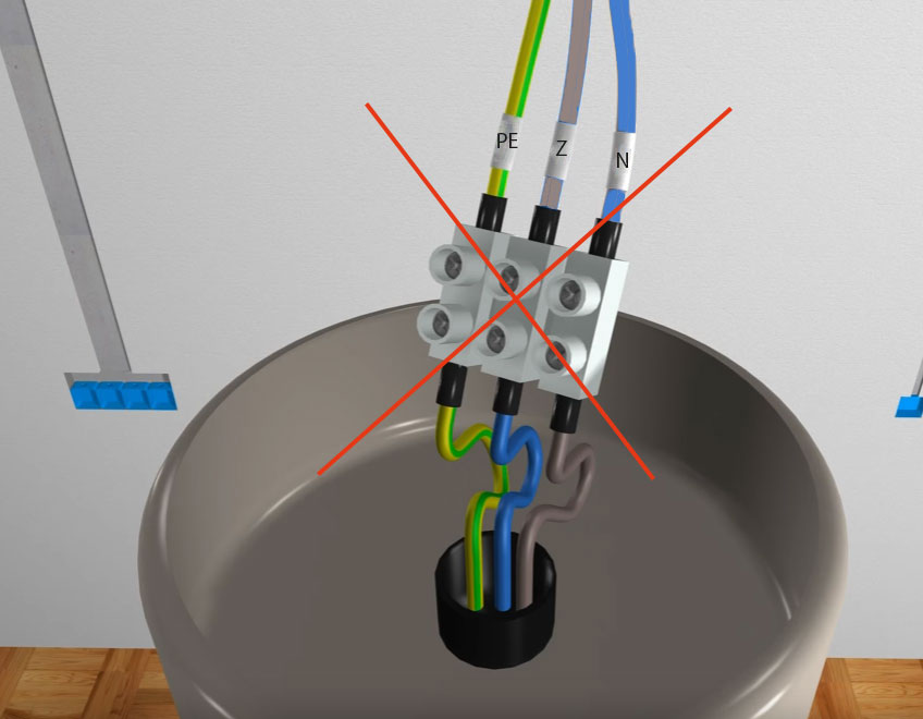 To avoid this, use and observe the color marking of wires, and even better, if you do not trust the colors, check the voltage supply using a high-quality indicator or multimeter before turning on the lamp.
In this article, we will look at how to connect a one-button switch and install it correctly. But first, let's figure out what this device is, how it works, and what varieties are used in everyday life.
- How to make the right choice
- How to connect correctly
- About security measures
- Dismantling
- How to change the layout
- Mounting site preparation
- Connection
Types of household electrical switches
A household electrical light switch is a device for closing and opening a circuit in order to connect or disconnect certain energy consumers. Most often, lighting devices act as the latter: chandeliers, lamps, sconces, etc. The 1-key switch can be used both for connecting single-lamp and multi-lamp devices.
In everyday life, two types of circuit breakers are used:
- invoices;
- embedded.
The first type is mainly used for installation on wooden or brick walls of premises with external (open) wiring. Such devices are attached to the surface using a special platform (socket box) and two screw-in screws.
Recessed light switches are installed inside a mounting box installed in a wall hole. They are intended exclusively for concealed wiring, which provides for preliminary chasing of walls, laying wires and hiding it with the help of subsequent puttying.
According to the principle of operation, both types are no different. It lies in the fact that when you press a key, the electrical circuit either closes, turning on the devices, or opens, turning them off.
Light switch design
Switch 1 key consists of:
- operating mechanism (button drive placed on a metal base, contacts);
- fastening mechanism (two metal "legs" movably connected to the base);
- keys made of plastic;
- decorative frame.
Additionally, the device can be provided with a constant backlight (LED), which helps to find it in the dark.
How to make the right choice
When choosing a 1-key switch, regardless of the type of installation and wiring, two points must be considered: the amount of current consumed and the level of humidity. The current for which the circuit breaker is designed is indicated on its operating mechanism. It should not be less than the current consumed by the connected device. As for the second point, if the installation of a single-key light switch is planned in a room with a high level of humidity, it is better to give preference to special waterproof models.
How to connect correctly
To save on electricity bills, our readers recommend the Electricity Saving Box. Monthly payments will be 30-50% less than they were before using the saver. It removes the reactive component from the network, as a result of which the load and, as a result, the current consumption are reduced. Electrical appliances consume less electricity, reducing the cost of its payment.
The basic rule for connecting a push-button light switch is that it must open the wiring phase, and in no case "zero". This is the only way to ensure safety when repairing a lighting fixture or replacing lamps. The connection diagram of a single-gang switch is shown in the figure below.

The ground wire shown in the figure is usually absent in residential buildings of old buildings, but if it is already provided by wiring, it is very desirable to use it, as indicated in the diagram.
About security measures
 Before starting electrical work, the electricity must be turned off. This can be done using a packet breaker (in old houses), an introductory two-pole circuit breaker or a load switch (in new houses). When the room is completely de-energized, you need to make sure that you are safe by checking the presence of electricity at the socket contacts using a phase indicator - a special electrical indicator.
Dismantling
After making sure that the electricity is turned off, we dismantle the old light switch (if any). To do this, you first need to pry off the plastic key with a screwdriver if this is a model for hidden wiring and unscrew the fastening of the decorative frame, or disassemble the device case if this is an overhead model for open installation. After that, you need to unscrew the two screws with a screwdriver that fix the “legs” with which the working mechanism is fixed inside the wall. When they are released, the device can be removed from the mounting box. For overhead light switches, after disassembling the case, it is necessary to unscrew the two screws (self-tapping screws) with which the working part is attached to the socket.
When the switching device is dismantled, you can disconnect the wires from it. In most push-button models, they are fixed with screws. Therefore, the screws simply need to be loosened and the wire pulled.
After disconnecting the device from the mains, determine if the phase wire was opened by the switch. To do this, turn on the electricity using the aforementioned bag, a two-pole machine or a load switch, and touch the phase indicator to each of the wires. If done correctly, it will light up on contact with the conductor that should come from the junction box. If the phase indicator does not light up when in contact with any wire, it means that the zero core has opened here, and the wiring will have to be redone.
How to change the layout
 In order to bring the phase to the switch instead of "zero", you will need to find and open the junction box. Next, you need to determine where the wires from the batch, load circuit breaker or two-pole machine fit in it. Among the incoming wires, using the indicator, you need to find the phase, and redistribute the cores in such a way that it goes to the switching device. A diagram of the correct distribution of cores inside the junction box is shown below.
Mounting site preparation
Before connecting a single-gang switch to the network, it is necessary to prepare its mounting location. For flush-mounted models, install (replace) the junction box, and for surface-mounted devices, the socket. The mounting box is simply inserted into a hole in the wall. In some cases, its installation can be carried out with its shrinkage on the putty. The socket for the outdoor switch is usually mounted on the wall with dowels and screws.
Connection
Having prepared the installation site, you can start connecting. Switch 1 key has two contact clamps, where the stripped wires are fixed with bolts. Each of the cores must be stripped of insulation by 5-8 mm. After that, the bare ends of the wires are inserted into the clamps and fixed with bolts, and it does not matter which of the conductors is connected to which contact.
At the end of the connection, check the reliability of the fixation, and only after that, the device can be mounted in (on) the wall. Switch 1 key for open wiring is simply screwed to the socket. For embedded models, this process is a little more complicated. After fixing the conductors to the contacts of the working mechanism, it is placed in the mounting box. "Paws", while should rest against its walls. Tightening the screws of the “legs”, the latter will begin to move apart, resting more and more. When the working mechanism is securely fixed, you can screw a decorative frame to it and install a key.
It remains only to turn on the electricity and check the results of their work.
Before the circuit for connecting the switch to the light bulb is implemented, it is necessary to think in advance how the electrical equipment will be placed. It is better to mark the markup on the wall so as not to miss some of the little things. Now you have to make the wiring and installation of equipment, and you need to do it so that everything works properly. In this article, we will help you figure out how to connect and carry out safe further operation of the devices.
Important! The main rule of the instruction is to turn off electricity from the network in order to avoid electrical injury.
Usually the switch is installed on one phase core, when it is turned off, the network opens, as a result, no voltage is supplied to the light bulb. It is worth noting that connecting the circuit in another way may be unsafe.
To place the wiring in the junction box, you need to stretch the cables to it that feed the entire room, then the wires coming out of the switch and the light bulb. Thus, we connect one wire from the light bulb to the neutral core, which is connected to the general network, the remaining one - to the switch conductor. The second core of the switch is connected to the phase conductor of the common power system. As a result, we get the connection of the working conductors of the lamp and the general wiring through the switch. Using a similar method, when switching the light switch, this part will be disconnected electrical circuit from nutrition.
What is needed to implement the scheme?
Be sure to select the switching method before direct installation, preferably connection using terminal blocks or spring clips. Then refer to our list and specify what tools will be needed for wiring:

Errors and malfunctions in the question of how to connect a switch to a light bulb
Often the expected from the installation work is not carried out. This is because in the process of connecting the electrical wiring, violations occurred or you missed some details. So, if the light does not light up when the switch is turned on, it is necessary to ring all current-carrying parts.
Be sure to check with the indicator whether the voltage is supplied from the mains to the switch. In the absence of it, we can safely say that mistakes were made when connecting the conductors to the general power system of the room.
Many homeowners have to change or install switches. Most commonly used single-gang switch wiring diagram- one of the simplest circuits for turning on lamps or lamps. This article describes step by step how such a scheme is assembled.
Before starting any work related to electricity, the first step is to de-energize the wiring - turn off the introductory machine, and also take measures to ensure that no one accidentally turns it on.
This is especially important if the electrical panel is located on the landing in a multi-storey building or on the street.
For installation and switch connections will need:
- - the switch itself;
- - junction box;
- - connecting wires;
- - insulating PVC tape.
Connection diagram of the switch in the junction box
Connecting the wire directly to a light or switch is quite simple - it does not require explanation.
This article will discuss how to connect wires from a lamp, an electrical panel and a switch in one junction box.
Once again, we want to remind you that all work on connecting wires in the junction box, connecting the switch and fixtures should begin only after the mains voltage is removed.
Following this simple rule, when the switch breaks exactly the phase, and not zero, you will ensure your safety, as well as make the operation of electrical equipment in your apartment safe.
If the switch does not disconnect the phase from the load, but the neutral wire, then the wiring will always remain energized, which is not only inconvenient, but also dangerous.

For example, you need to replace a light bulb that burned out in a chandelier. If the switch turns off the neutral wire, and not the phase, if you accidentally touch the current-carrying parts of the chandelier or the base of the light bulb, you may be struck by an electric current, since these parts are under phase voltage.
You can determine the phase wire in the distribution wiring using an indicator screwdriver.
Again, for safety reasons, the phase wire (usually red) must be connected to the lamp socket in such a way that the bulb is connected to the phase by the central contact of the base.
This reduces the likelihood that a person will touch the phase wire.
Switch wiring diagram consists of one or more electric bulbs connected in parallel, a single-gang switch, a junction box and a 220 volt power source.
Specialized stores offer a wide range of wires for electrical wiring, so it is better to take wires of different colors for phase and zero, for example, red and blue.
So with switchboard a two-wire cable is connected to the junction box. It is very convenient if it is two-color, for example, the phase wire is red, and the zero wire is blue.

In addition to it, the cable from the lamp and the cable from the switch are suitable for the junction box. The phase wire from the switchboard (red) is connected to the red wire going to the switch.

The second (blue) wire from switch connects to the red wire, which is connected to the load (lamp, chandelier). As a result, we made the phase that goes to the lamp switched.
The neutral wire (blue) from the electrical panel is connected to the neutral wire that goes to the load (light bulb).
As a result, it turns out that the neutral wire from the junction box goes directly to the light bulb, and the phase is connected to the light bulb through a switch.

The scheme works as follows. When the switch button is pressed, the circuit is closed, and the phase from the electrical panel is supplied to the lamp, its lamp starts to shine. By pressing the button again, the electrical circuit is broken and the lamp turns off.

After all connections, the twisting points are well insulated and neatly stacked. It is best to connect the wires in the junction box by twisting with soldering.

Scheme of connecting a socket and a switch in one junction box
Very often, a junction box is installed in each room of the apartment, where all the switches, lamps and sockets of this room are connected.
In this case, due to the large number of wires suitable for the junction box, it is quite difficult to figure out what needs to be connected and where.

How to connect a socket and a switch to a junction box?
Consider the option when a socket and a lamp are simultaneously connected to one junction box.
So, two wires come from the switchboard to the box - red (phase) and zero (blue).
The procedure for connecting the switch and the lamp is exactly the same as discussed above.
The socket is connected in parallel with the supply wires: the phase of the socket is connected to the supply phase (both wires are red), and the zero from the socket is connected to the neutral supply wire (both wires are blue).

A light switch can be a simple electrical device, as well as a complex switching device. They are designed for different lighting control schemes. When wiring, it is important to correctly connect the light switch. The connection scheme in the classic version is the use of the simplest device with one key.
Its contacts open when the light is turned off and close when it is turned on. In this case, the phase passes through the switch, and zero is connected to the lamp. It is impossible to confuse the connection order, otherwise there will be constant voltage on the lamp.
Connecting a single-gang switch
Devices are made for indoor and outdoor installation. A single key light circuit provides switching of a luminaire or a group.

If there are more lamps, the main connections are also made through the junction box.
Features of using multiple keys
The double light switch circuit allows you to control the same number of fixtures. Here, the lamps are switched separately through one switching device, depending on which of the two keys is pressed. The method is common for turning on a chandelier. Three-key models are less commonly used.
The difficulty of replacing with a device with a large number of switchings lies in the need to lay additional phase wires to the fixtures and the switch. Connection diagrams are marked on its rear side (three outputs for a two-key device).
In essence, the switch is two simple devices combined in one housing. When one of the keys is turned on, the phase is fed to the corresponding lamp. Voltage is supplied to the input terminal (clamp). Two contact groups are connected to it, each of which has its own key. Lamps are connected to the output terminals.
A three-key light switch works in a similar way. The principle of operation is to switch the wires connected to individual lamps or their groups.
Connecting the lighting system in an apartment or house
In houses and apartments, power and lighting circuits are separated from each other and protected by separate machines. When the first of them fails, the light still continues to burn, which facilitates troubleshooting and troubleshooting. If the second circuit fails, it can be repaired by plugging the carrier into any of the outlets.
The lighting system is protected from short circuits and excess of the long-term permissible current by an automatic switch with a rating determined by the total power of all lamps.
Switch device
The following types of household switches are produced:
- internal;
- outdoor;
- with protection against moisture;
- modules.
When mounting in the wall, models for hidden wiring are used. First, a recess is drilled in the concrete, into which a socket is inserted and wires are laid. As a result, the device is inserted into the wall and is located at the level of its surface.
The switch and socket are sold separately. They must match each other as well as the installation conditions in a wall or in a thin partition.
External switches are used for open wiring that runs through pipes or cable channels. A wooden or plastic platform is installed under them, attached to the wall with self-tapping screws or dowels.
The modules are mounted on special cable channels and are used in offices or enterprises.
Devices with protection against moisture are installed in bathrooms, baths, in other damp rooms or in places where drops of water can fall on them.
How to connect a light switch: diagram
The elements to which the wiring is connected are terminal blocks - mechanisms with self-clamping contacts. To connect, the end of the core is stripped and inserted into the hole, where it is clamped with spring-loaded contacts.
Instead of terminals in the switch, screw terminals can be installed. The end of the stripped core is inserted into them and tightened by tightening the bolt.
The switching mechanism contains a movable contact that occupies 2 fixed positions: "on" and "off". Depending on which of them the key is located in, it will be closed or open.
Switch selection
The device is bought in a specialized store, where you can choose the most suitable in appearance and parameters. The switch must match the power of the fixtures. Its price depends on it. For example, contacts made of cermet containing silver are rated for an electric current of 4 A.
With a variety of designs, switches should be selected for a specific purpose. They can be keyboard, push-button, wall-mounted, ceiling-mounted, rotary, cross-over, walk-through, etc. Particular attention is paid to whether the light switch is intended for external or internal wiring. Its connection scheme is also important, since it performs a specific function.
It is important to check the build quality of the device and how clearly the keys switch.
Touch light switches
The outer panel is a glass decorative plate with markings. Under it is a sensitive element that reacts to a light touch or the approach of fingers. In this case, a signal appears, which is converted by the semiconductor circuit into an electrical one, perceived by the switching part. Depending on the place or duration of contact, the electrical circuit is closed or opened, as well as the brightness of the lamps is smoothly regulated.
For greater convenience, remote control panels are used that are associated with several switches of the same type.
The number of functions for different models is different and depends on the price. The devices are equipped with motion, temperature, light sensors, etc. An electric fireplace, air conditioning, lights and a security lighting system around the perimeter of the house can be connected to them.
The principle of operation of the touch switch
There are many electronic circuits. Below is simple circuit light that you can collect with your own hands.
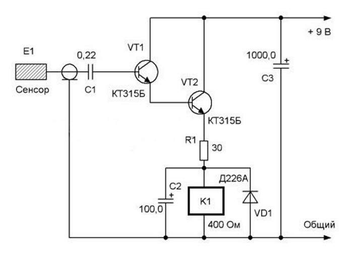
When a person touches the sensing element E1, a slight potential from the body is transferred to the two-stage amplifier through the capacitor C1. Relay K1 is connected to the output of transistor VT2, which is activated or turned off at the next touch. Its power contacts are connected to the lamp power circuit (not shown in the diagram). Capacitor C2 is a filter that smooths out voltage ripples, and diode VD1 protects transistor VT2 from voltage surges.
This light switch circuit contains the operation of which is 15-20 mA. To adjust it, R1 is connected and the resistance is changed until the contacts begin to switch reliably. Then the appropriate value is selected.
The sensor plate is made of foil textolite or a copper plate coated with anti-corrosion varnish. The lead wire is shielded.
The battery can be a 9V battery or Charger from phone.
Through switches
The devices are designed for convenient lighting control in long corridors, stairs, walk-through rooms or downstairs to the basement. Several switches located in different places are convenient to use for one lamp. Lighting control becomes more comfortable and economical.
Light switch circuits
The devices contain 3 contacts on each of them (1 common input and 2 changeover output). From two switches located at a distance from each other, you can assemble the simplest and most common lamp control circuit.

When a key is pressed, one of the changeover contacts opens one circuit, while closing the other (or vice versa). In the first switch, the input terminal 1 is connected to the phase, and in the second - to the lamp. Output contacts 2 and 3 of one apparatus are connected to the corresponding ones of the other.
When properly connected, the lamp should turn on and off in sequence when one of the switches is toggled. When one circuit breaks, both lines are prepared for the next connection. Here, each key does not have a fixed "on" and "off" position.
Below is a picture of how the light turns on with two switches. The circuit is assembled mainly through a junction box. All major connections are made in it. In order not to be mistaken when connecting, the wires should be marked.

Two-gang pass-through switches
The scheme for connecting light with two switches to control one lamp or group is the simplest. If you take more complex - two-key, you can independently control two lamps. At first glance, the circuit seems complicated, but, in fact, it consists of 2 connections for a pair of single-gang switches. This doubles the number of inputs and outputs.

After the circuit is assembled, it is advisable to check it with a multimeter. To do this, its probes should ring the input and output contacts of the switch. Switching the keys, you should follow the tester readings. If the circuit closes and opens as expected, the circuit can be connected to the network.
Conclusion
For specific lighting control conditions, a specific light switch is used. The scheme of its connection is directly related to the design features. The most common are simple models that provide opening or closing of an electrical circuit. The scheme is complicated by the use of two and three keys, with which you can switch the same number of lamps or control the brightness of the chandelier. In addition to them, pass-through switches appeared, allowing you to adjust the lighting from different places. Then, remote and touch control systems began to be produced, due to which the functionality increased significantly. Despite the high prices, such switches are increasingly used due to the creation of comfortable conditions and energy savings.