Star News


How to assemble a three-phase electrical panel. Street shield on the site
So a holiday has come on our street - Lenenergo contractors from Belgorod have finally built the promised VLI-0.4 kV to our and several other sites. But I prepared for this event in advance - the introductory shield was already assembled.
I decided to take a cheap shield case - IEK, IP54, dimensions 445x400x150. For outdoor installation outside the site just right. Although it looks pretty decent on the outside, the build quality inside is also quite good. There are no holes, the seal fits snugly around the entire perimeter, the mounting plate is made of sufficiently thick sheet steel.
The "chip" of all IEK shields is crookedly installed DIN rails. But I also have a din-rail counter, so I removed the regular short DIN rails and fixed three rows of a good rigid ABB DIN rail with rivets for the entire width of the shield.
I decided to take the introductory machine with characteristic D, to ensure the selectivity of short-circuit protection. Type D is the slowest and should fire last. Further in switchboard in a change house (and then in a house) for each phase there will be a separate two-pole introductory automatic machine of type C, and on consumers already automatic machines of type B, the most paranoid.
The introductory machine is four-pole. Three poles - working power, one per phase. The fourth pole will be used as a signal, according to the state of which I can remotely control the position of the contacts of the introductory machine. This is necessary so that the smart home system can adequately report the problem - what type of power failure has occurred, or the machine has been cut and you have to drag yourself to the shield, or the power has disappeared at the input and you need to start the generator and switch the input to a backup input.
I thought for a long time what to take - a three-pole machine and an additional signal module (which is cheaper), or a four-pole machine. I settled on the latter option, because I thought that it was more reliable and durable. After all, the introductory machine must be closed with a sealing lid and I will not have access to it. And the additional signal module looks more flimsy, and I'm less sure of its reliability.
But for the RCD, which I decided to put after the counter, I just took an additional signal module. There are no other options here, it is only possible to control the state of the RCD remotely in this way. The RCD in the shield is without sealing, in which case I can always get free access to it.
The shield was mounted with a flexible stranded wire with a cross section of 6 mm2. produced by Alyur. Before choosing Alur, I made a test purchase of 1 meter of different colors of wire from 5 different manufacturers (Alyur, Promel, REK, Kolchugino Electric Cable, Exvayer), checked all the wires for cross-section and crimp quality, for flexibility and insulation quality. The vaunted Kolchuginsky cable upset with its different diameters of insulation on wires of different colors, although otherwise it was good. Other brands disappeared for other reasons (someone badly crimped, someone had a section that was lower than the declared one, someone had a wire that was too soft and did not completely restore its shape). The wire "Alyur" in my rating took the first place, as it did not reveal any shortcomings of competitors.
I fixed long bundles of wires on self-adhesive mounting pads and nylon clamps. There is no special meaning in this, rather for aesthetics.
To connect the outlet cable, I decided to use phase terminal blocks. Firstly, it will be more convenient to mount the cable. Secondly, the terminal blocks have several clamps and are designed, among other things, for branching lines, that is, in the same shield, it will then be possible to power something else additionally.
For signal wires, I also used terminal blocks, also for the convenience of connecting outgoing cables. I fixed all modular elements on DIN rails with locking stops. There was no great need for this either, but mounting such a shield is much more pleasant - everything is rigidly fixed and does not crawl anywhere. Unless it was possible to press the zero terminal blocks from the second side - the clamped wires just go there.
I thought for a long time whether to install SPDs and according to which scheme. Haven't figured it out yet...
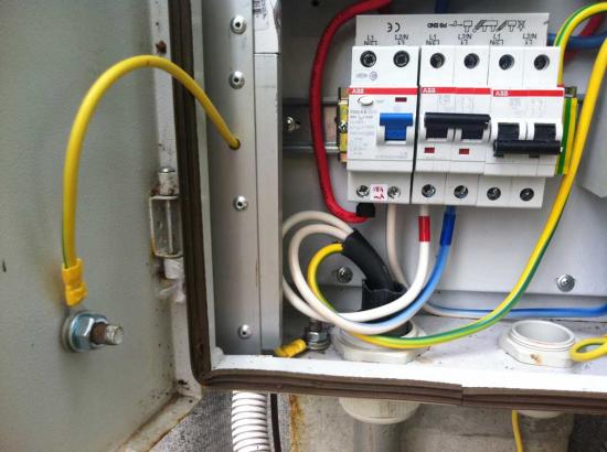
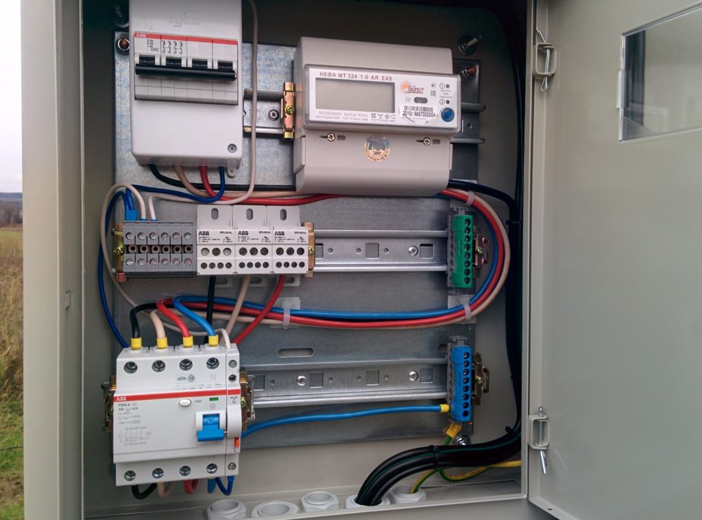
The assembled shield looks like this:
It only remained to figure out how to fix it on a support. At that time, I was sure that the VLI supports would be delivered to us with wooden ones, as they do now everywhere. I looked at the neighbors - who is in what much, but basically no one was soaring, the shields were simply fixed to a steel tape.
Such fasteners did not suit me, as it looked flimsy and completely non-vandal resistant. I did not find any ready-made solutions with rigid brackets for round supports on sale. The question hung and did not want to be solved.
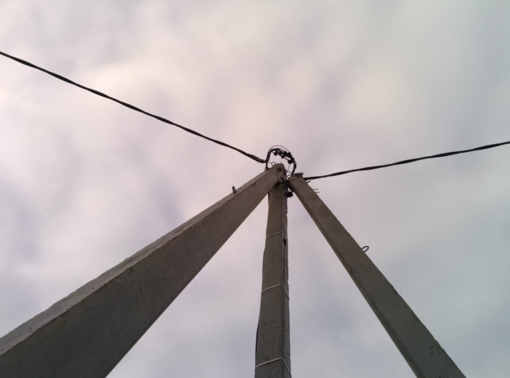
Well, while I was procrastinating about this, they brought supports and, lo and behold! They turned out to be reinforced concrete, rectangular (trapezoidal) section. Intuition did not disappoint - it’s good that I didn’t have time to make a mount for a round support.
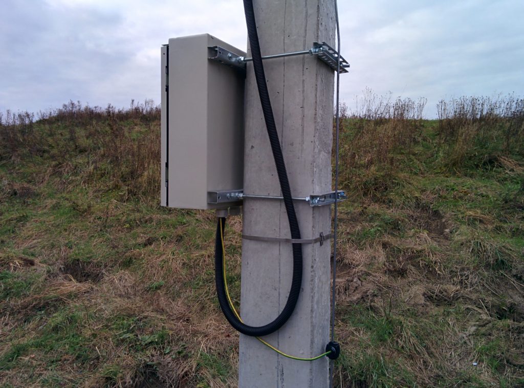
Now everything has become much simpler and clearer - a U-shaped profile, pulled together with threaded studs. I bought a profile, threaded rods, cut it, got an excellent mount. Fitting: 
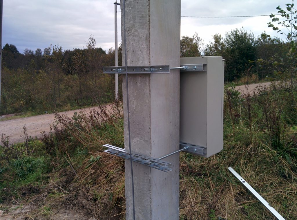
Profile pieces far from the shield look ridiculous. But until I tried it on, it was not obvious. Then he trimmed the uselessly protruding ends.
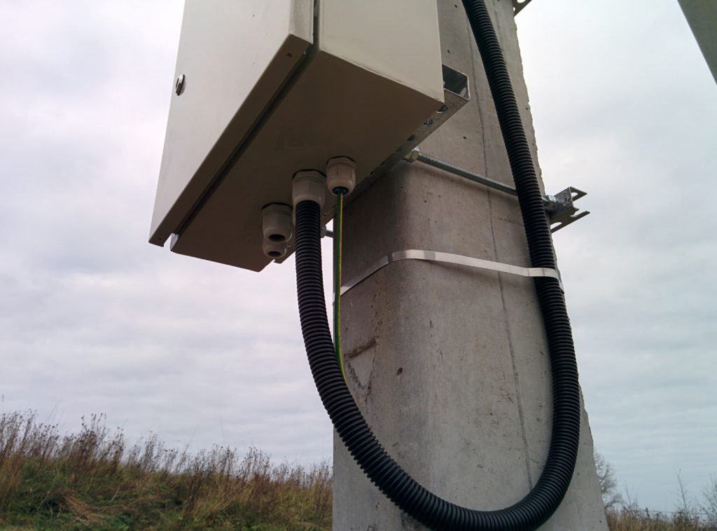
Regularly in the shield there were only two holes for cable entry. But that wasn't enough for me. Firstly, it is not clear how to output the ground wire. Secondly, I planned the signal wires, and they needed a separate input for them. Well, for some additional equipment that can be installed later (automatic street lighting, for example) also needs a separate input. Therefore, I pre-made three more holes in the shield for oil seals of a smaller diameter.
Installation of the descent (cable from the top of the support to the shield) according to the specifications, the applicant must carry out on his own. That is, hire a contractor, pay for the work. Well, or climb yourself. Optional. Papers confirming the qualification of the work performed are not required. It only requires the presence of an actually mounted descent and shield.
Nenuacho, yazhspetsialist, why pay someone and hope that they don’t cheat. I’ll climb, as I myself, on a support, and I’ll connect everything as it should be. Moreover, the line has not yet been powered (the subcontractors have not yet installed the STP), there is no danger. The Internet is full of information on how to do it, and I asked Lenenergo a direct question over the phone: “can I do it myself?” - "Yes, please!" Lenenergo reiterated their requirements to me over the phone (the main ones, which are spelled out in the TU).
Bought SIP, fittings. Well, cats to climb the pole. In general, I would not buy cats for the sake of one case, but in the future I plan to hang lighting on nearby supports. And then maybe a surveillance camera. And I will have to climb the poles anyway, not to call the electricians every time. In order to just climb onto the support and connect the SIP descent, without connecting to the shield and mounting the shield itself, and without materials, the electrician asked for as many as 3 thousand. This is just to climb, connect, fix the wire to the pole, get off. Everything. Danuegonafik, cats cost 3200, but many times and complete freedom.

I had never climbed poles before, but I saw how easily and simply electricians do it, so there were no doubts about the feasibility of this enterprise. Indeed, in practice it turned out to be easy. A couple of minutes to get used to the crampons at the bottom of the pole, to figure out exactly how to place them for a secure fit, and I'm ready to climb.
A safety belt is an obligatory element of ammunition, without it I would not even think about lifting. I have had a belt since Soviet times. Although in the end its functions were not useful, and it most of all interfered and slowed down progress. But it was the presence of insurance that gave confidence in the safety of the process. Even downstairs, I checked how I would hang on the insurance if I fell off the crampons (and it’s very easy to break off the crampons, in fact, if you make the wrong movement with your foot). The holding strap, which I wrapped twice around the pole, held my weight securely without a hint of slipping. There was no risk of falling, so I calmly got to work. Fortunately, I have no fear of heights, provided that there is no risk of falling from it.
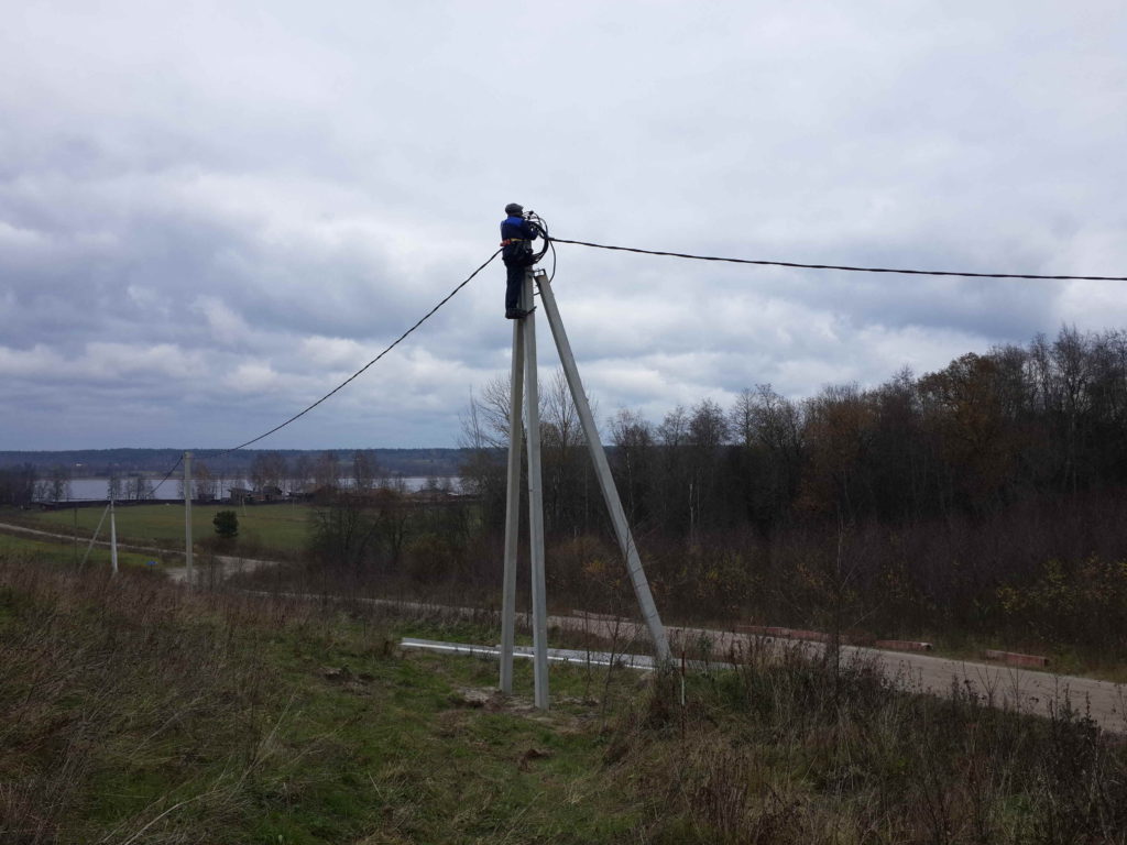
But at the very top of the support there was one unpleasant moment. Since this support is a tripod, and I had to rise above the point of the bundle of jibs, it was necessary to refasten the insurance. The hardest thing was to overcome the thought that for a few seconds I would still have to risk falling down. But I completely focused on the process, securely fixed both cats, jumped on them, and re-fastened the insurance without letting go of the post from my hands.
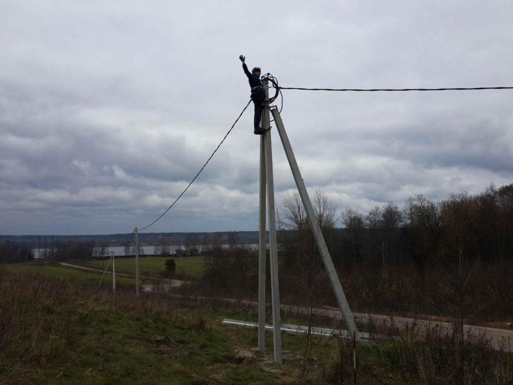
Everything went perfectly and without problems. At the top, I connected the descent wires to the main wires with piercing clips with break heads. He also did this for the first time in his life, and immediately at a height of eight meters above the ground. Nothing complicated.
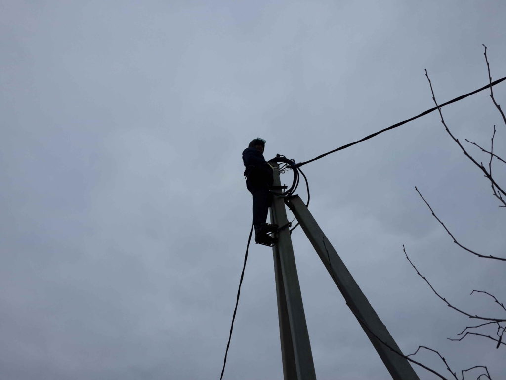
The weather was windy, and I put on safety goggles so that my eyes would not water and it would not interfere with work. However, at the time of the ascent, the wind died down, and my glasses did not come in handy. I also prudently put on gloves with a continuous anti-slip coating. The SIP wire is very slippery, and the concrete support is quite smooth. At the top, everyone was afraid to drop something, and then they would have to repeat the ascent. But he did everything without fuss, thinking through all the moves in advance, and there were no fails.
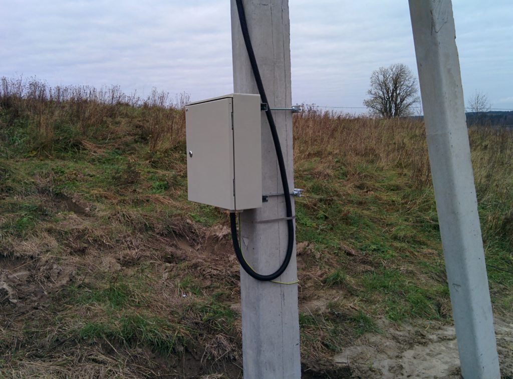
In the process of descending from the support, every 0.8 meters I fixed the cable, previously threaded into the HDPE corrugation, with a steel tape. I don’t have a special tool for tightening the tapes, so I tightened it as best I could by hand. But, a lot of effort is not required here: 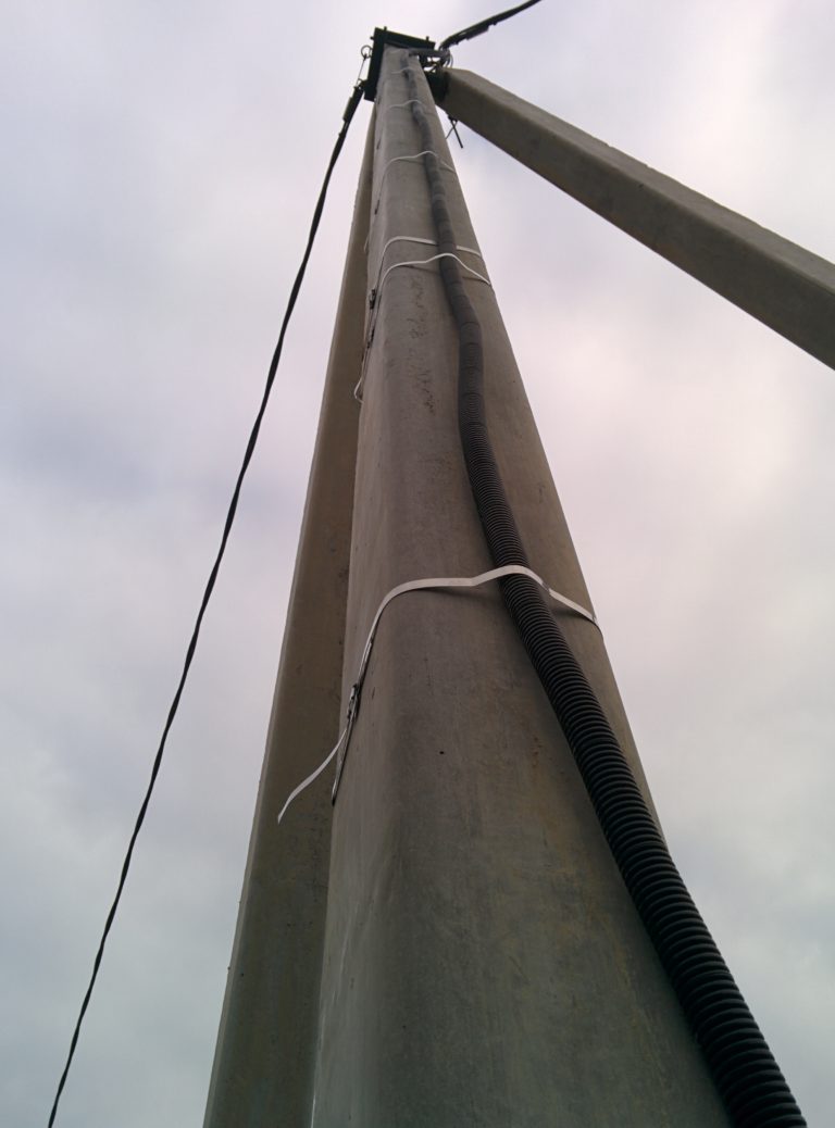
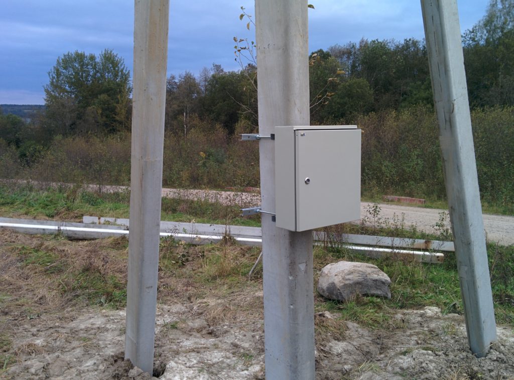
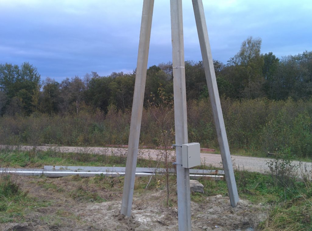
Then everything is simple. I fixed the shield on the support with pre-made brackets, started the cable, connected it. I made the grounding of the door, the shield body and the mounting panel by connecting the support through the clamp to the grounding. Zeroing in the shield did not. Zeroing is done at the top of the support, this is enough. In addition, Lenenergo requires either a sealed input zero terminal, which I could not find on sale, or a zero core plant directly into the meter, which I did. You can make zeroing after the counter, but there is no need for this.
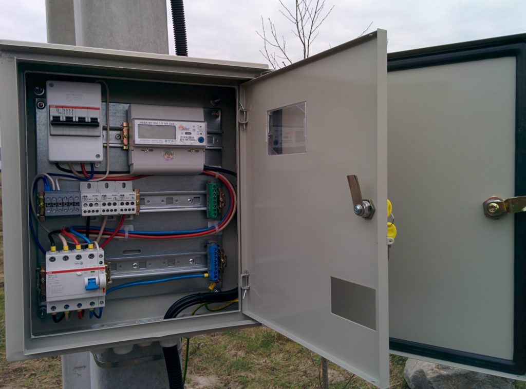

The seals that were not used so far were clogged with segments of the SIP wires to ensure tightness: 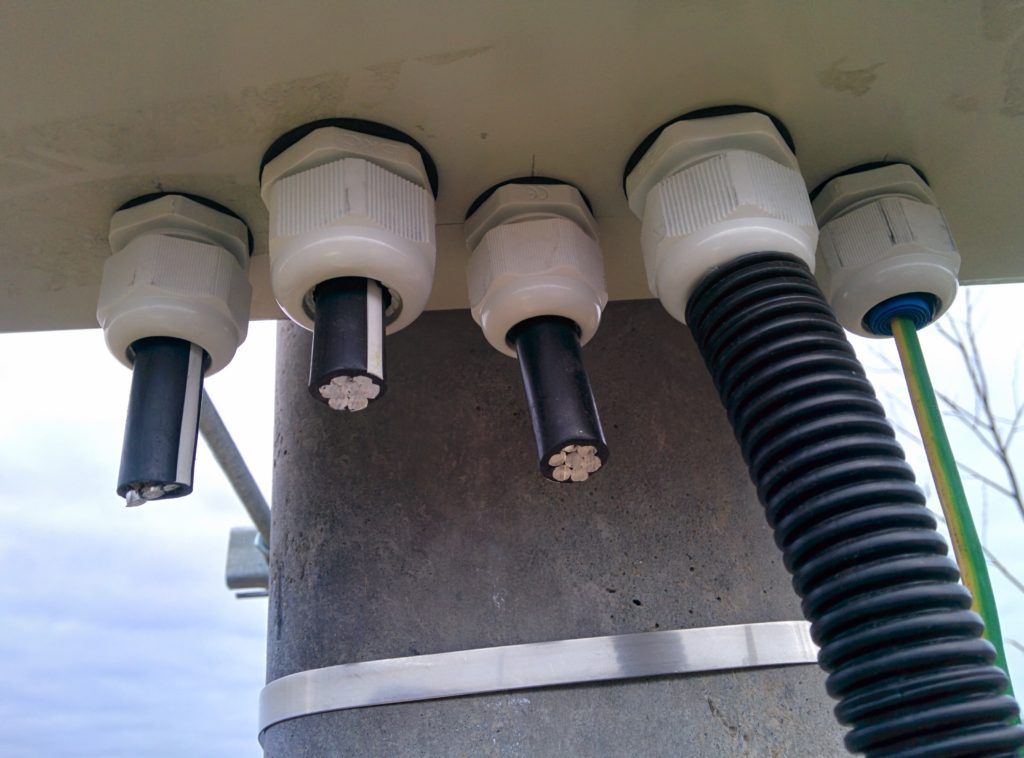
The shield is ready. Now it remains only to wait for our zero-four to be connected through the TP to the ten and “supply voltage and power,” as the contract says.
While I was digging in my shield, a hired electrician from Lenenergo managed to mount the descent and shield on the neighbor's site. I did not find the electrician, but I went to see more closely how everything was done. Once again I was convinced of the truth of the expression "if you want to do it well, do it yourself." I, not being a professional electrician, performed the entire installation many times better and more correctly than a professional from a monopoly company.
Absolutely everything was done there badly. The descent is dressed in a corrugation with a diameter twice that required, which is why it was jammed in places of puffs. The descent is fixed to the support in only three places, and not with steel tape or reinforced ties, but with ordinary thin ones. The input to the shield is made without an oil seal, just through a hole in the housing, there can be no talk of any tightness. The ground wire is without a terminal, it is simply screwed onto the pin under the nut, and also without a gland, it is removed from the shield. A hole is cut in the cover of the meter for the wires so as not to bathe with molding and laying. The shield itself is fixed to the support with flimsy corners made “on the knee”, everything is kept just so that it does not fall. Well, it will work, of course. But how hand-crafted and collectively done ... It's good that I began to do everything myself, I never regretted it.
Expenses
- Shield SCHURn-3 IP54 445x400x150, IEK - 2452 rubles. (ETM, MKM51-N-09-54)
- Shield ShchRn-P-4 plastic IP30 130x90x65, Tuso - 33 rubles. (ETM, 68024)
- Counter Neva MT324 ARE4S, Taipit - 4105 rubles. (ETM, 6109137)
- RCD F204 A-25 / 0.1, ABB - 4512 rubles. (ETM, F204 A-25/0.1)
- Automatic four-pole S204 25A D, ABB - 4961 rubles. (ETM, S204 D25)
- Signal contact S2C-S / H6R, ABB - 506 rubles. (ETM, S2C-S/H6R)
- Terminal block BRU 80A, ABB, 3 pcs - 2451 rubles. (ETM, 6208R2500)
- Screw terminal M6 / 8 6 mm.kv, ABB, 6 pcs - 358 rubles. (ETM, 5118R1100)
- End insulator FEM6 MA2.5-M10, ABB — 26 rubles. (ETM, 8368R1600)
- Terminal EARTH 8x1.5-16mm.kv. green, Legrand - 430 rubles. (ETM, 004832)
- Terminal 8x1.5-16mm.kv blue, Legrand - 578 rubles. (ETM, 004842
- DIN rail 1000mm ED4 width 4, ABB - 422 rubles. (ETM, ED4)
- DIN rail limiter, IEK, 8 pcs - 94 rubles. (ETM: YXD10)
- Cable gland PG-21 IP68 13-18 mm, DKC, 2 pcs — 90 rubles. (ETM, 53000)
- Pin tip NShVI 6-12, KVT, 200 pcs - 278 rubles. (TechElectro)
- Pin tip NShVI(2) 6-14, KBT, 200 pcs — 508 rubles. (TechElectro)
- A set of tips NShVI No. 5, KVT - 856 rubles. (TechElectro)
- Power wire PuGV 1x6 red, Alyur, 10 m - 376 rubles. (ETM, 0304402001)
- Power wire PUGV 1x6 white, Alyur, 10 m - 360 rubles. (ETM, 0304401000)
- Power wire PUGV 1x6 black, Alyur, 10 m - 376 rubles. (ETM, 0304400000)
- Power wire PUGV 1x6 blue, Alyur, 10 m - 376 rubles. (ETM, 0304403001)
- Power wire PUGV 1x6 yellow-green, Alyur, 3 m - 108 rubles. (ETM, 0304406050)
- Pad 7.6 mm self-adhesive 25x25 white, 100 pcs - 200 rubles. (Maxidom)
- Nylon clamps 300x4.8, 100 pcs - 300 rubles. (Maxidom)
- U-shaped profile, threaded rods, fasteners - 1500 rubles. (Maxidom)
- Branch piercing clamp for SIP, 4 pcs - 448 rubles. (NER)
- Stainless steel bandage tape steel, 8 mm, 25 m and braces 10 pcs - 752 rubles. (NER)
- Manholes universal LU (cats) for reinforced concrete supports - 3200 rubles. (NER)
- Reinforced ties for SIP KSU 6x180, 100 pcs - 570 rubles. (TechElectro)
- SIP-4 cable 4x16-0.6 / 1, 12 m - 842 rubles. (ETM)
- Safety belt - was in stock
Putting an electrical panel on the street is not such an absurd idea as it may seem. The reasons for such a technical solution are as follows:
1. Energy sales organizations often insist that the meter for electricity consumption and, accordingly, be located within the reach of the inspector. This is especially true for large country residences, where the owners can relatively easily “hide” an additional input past the meter with known targets in the house. On the other hand, the shield on the street support is clearly visible from all sides and does not arouse any doubts or suspicions in the inspector.
2. In the same country residence, the introductory electrical panel can also be very impressive. And the desire to save on space and take at least a metering device and input outside the house is quite understandable.
3. In the end, the switchboard may simply not fit into the interior of the living space, especially if the latter is designer. In this case, you can not only take the shield to some utility room, but also go further by placing it on the street.
Well, and, of course, placing the shield on the street has its drawbacks. Here they are:
1. Despite the technical conditions from energy sales companies, an electric meter on the street may be a violation of clause 1.5.27 of the PUE, which states that electric meters can be placed in unheated rooms and outdoor cabinets only if there is local heating that provides a positive temperature for the meter. And it is not always easy to comply with such a restriction.
Meanwhile, an induction electric meter at negative temperatures inevitably begins, simply speaking, to “lie”. Moreover, “lying” is not in favor of the subscriber, so Energosbyt does not care much about this circumstance. For the subscriber, this is a significant disadvantage.
2. located in the street shield is not very convenient. Especially if it is winter outside, and the shield is at a significant height for security reasons in front of thieves and hooligans. A shield standing high on a support is inconvenient to repair and maintain: at least you cannot do without a ladder.
3. By placing a shield with group devices on the street, we will be forced to pull group lines from there as well. Moreover, the larger the house itself, the more these lines will be and the more impressive the “web” connecting the introductory shield and the building will be. There is little good in this, even if the "web" is hidden in a pipe located underground.
Therefore, for a solid cottage, the option of placing group machines in a street shield is no longer possible: such a technical solution is only acceptable for country houses, garages and other small buildings. And the advantages of a street shield, in which only an introductory machine and a counter are installed, are no longer so obvious.
Composition and electrical panel for outdoor installation
In the composition of the street electrical panel, first of all, there is an introductory machine with two poles for a single-phase network and four or three poles. An additional pole will be possible to use to completely turn off the network and break, including the neutral conductor. This will be useful in case of malfunctions in the mains supply itself, which, unfortunately, also happens sometimes.
The introductory machine provides not only the ability to turn off the network, but also protects it from overcurrent. However, in addition to this, fire-fighting differential protection of the network is also necessary, which can be provided using a differential, and not a simple introductory circuit breaker. Another option is a separate RCD, which will be installed immediately after the input device. The value of such an RCD should be 100-300 milliamps.
After the introductory machine and the differential protection device, it should be placed, designed for the corresponding number of phases. If the load in the network does not exceed 100 amperes, then the meter can be directly connected. If the load is more than 100 amperes, then the meter will have to be connected through current transformers, which will lead to a significant increase in the dimensions of the shield.
This is the minimum set of devices. It can be supplemented, for example, with the help of a set with a shunt release for the opening machine. But besides this, it is necessary to include equipment in the shield to maintain a positive temperature in the winter. The simplest solution is a modular thermostat paired with special panel heaters available from most major manufacturers of electrical modular equipment.
In addition to the devices in this shield, zero buses PE and N should be placed, united by a jumper. If the body of the shield is metal (which is most likely for outdoor conditions), then it should be grounded by connecting it to the PE bus. To the same PE bus using a copper wire with a cross section not less than the cross section of the input phase conductor, you should connect a repeated grounding device located in the ground at the place where the shield is installed. It can be made from several steel vertical bars with a diameter of about 16 mm or corners of equal cross section, interconnected by means of a welded steel strip 4 * 40 mm.
Since the input and the electric meter are, according to the power supply companies, deeply intimate things, the box in which this equipment will be placed must be sealed. In this case, the user should only be able to take readings and turn on / off switching / protective devices. The shield itself must be securely closed and locked with a key.
In addition, since the shield will be located on the street, it must have an increased degree of protection against external influences: usually at least IP54.
Installation of a shield on the street
The place for installing a street shield usually becomes, after all, not a street in literally, and the yard or plot, in general, is a personal territory. This choice is made for reasons of elementary security.
To install the shield, an additional separate support is most often used, which becomes mandatory for long branches. If there is no such support, then you can build a rack from improvised materials. The shield itself must be securely fixed in level, for example, using through bolts.
Energy supply companies often insist that a street panel with a meter be mounted at a height of 3 meters or more. With such an arrangement, safety is of particular importance: it is necessary to take into account both the effects of wind and the fact that over time the fastening may become weaker.
It is better to enter the shield through intermediate insulators so that the input wire / cable, swinging, does not fray its insulation and does not pull out. The outgoing line does not have to be made air, you can put it in a pipe underground.
Alexander Molokov
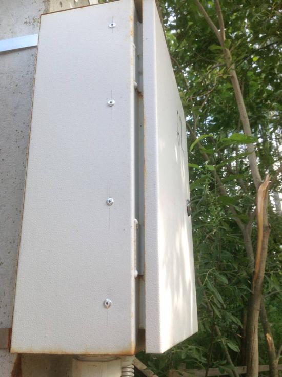
It's time to rework the introductory shield on the pillar.
For the milestones of the SNT members, a power of 4 kW has been allocated. I don’t know what such a restriction is connected with - it seems like everywhere they allocate 10-15 kW to everyone without any problems.
Be that as it may, our networks are practically new, they were carried out by SIP.
I agreed to double the capacity. As a result, under the contract with Energosbyt, an input of 8 kW per one phase will appear.
The entrance to the house will be laid with a VVGng 3x16 cable in a technical HDPE pipe.
Grounding according to the TN-C-S system.
I was banned from altering the inlet cabinet on my own, citing the fact that the shield would not be accepted and this alteration should be carried out by an electrician ...
For the shield was purchased:
- introductory machine for 40A from legrand
- selective RCD for 300mA from ABB
- 40A home machine from ABB
- automatic 25A from ABB for an additional shield on the site (for welding, etc.)
- for organizing PEN branching
- M10/10 terminal for the ground wire output for the cable, which will subsequently be connected to the 25A machine
- installation was carried out with a wire PV3 10 squares in double insulation.
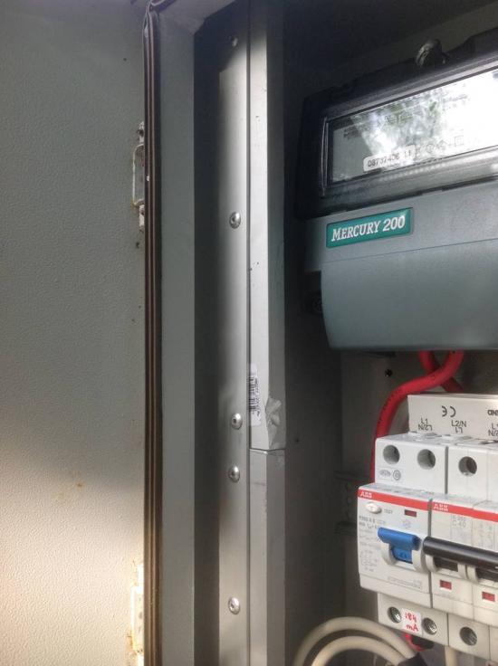
The counter remained the same - Mercury 200.02
The cable for connection on the pole was laid in advance and was waiting in the wings.
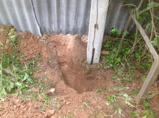
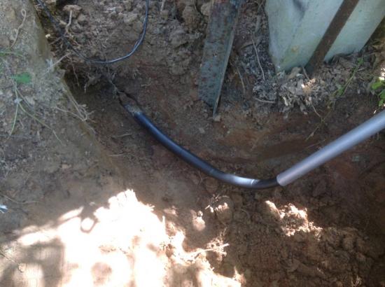
A trench was dug to the pole into which the cable was laid. From above, for protection, I laid special plates so that in the future I would not break through it with a crowbar or a shovel.
I talked about these plates.


I put a metal pipe on the HDPE pipe, which I previously painted in gray.

In a metal shield, using a "cricket" (a device for cutting metal with a drill), I expanded the holes for the seals.
Using a step drill, an additional hole was made to enter the SIP cable. They didn’t put an oil seal under it - the shield is so not airtight that there is no special meaning in it. The hole and corrugation were processed so that the cable was not damaged by the edges.
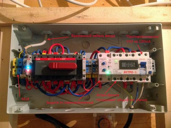
The scheme of the shield on the pole turned out like this:
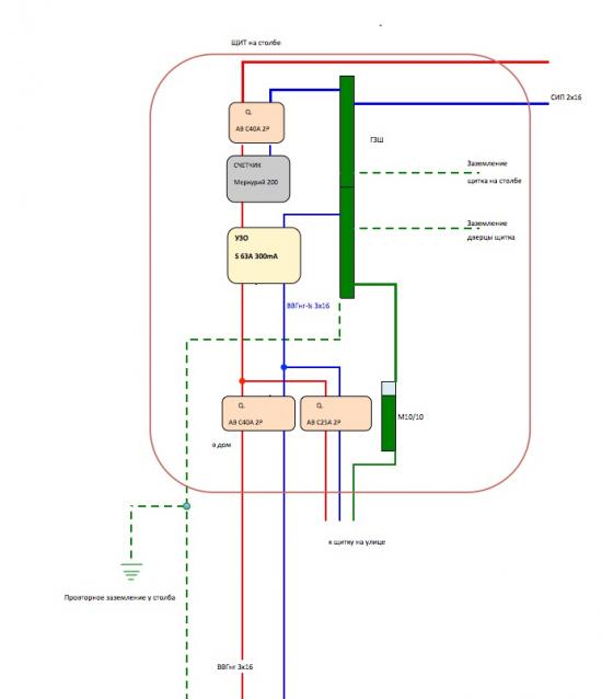

Since three modules were used from ABB, I took a regular bus to connect them. This made it possible to make the installation compact and it was not necessary to fiddle with the cable to connect them.
The only thing that when using the bus, the cable entry into the RCD had to be done from below, and not from above. But this is not critical - you can do it that way.
The RBP-95 block was used in order not to tear the PEN cable, but simply to pass it through, cutting off the insulation.
The ground connection was made with a crimped conductor of the PV3 wire of 16 squares.
Crimped with a manual hydraulic press from KVT PGR-70.
They fastened with M8 bolts directly to the RBP-95 distribution block - the fastening is visible in the photo.

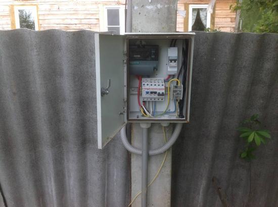
Since the old shield was used - the one that was previously on the pole, then for internal peace of mind and from the "pioneers" it was decided to make an internal opening / closing door from duralumin.
I had a piece of duralumin, as well as the corners, which I attached with rivets to the inner side surfaces of the cabinet, stepping back from the edge of 2.5 cm.
It turned out that the door is slightly ABOVE the machines, but this does not interfere with their control.
It so happened that the 3x16 input cable is so "oak" that it was not possible to additionally press it so that the home-made plastron door could be lowered closer to the machine.
Well, don't be scared...
Riveted corners measuring 20x40mm.
On the left side, before installing it in the cabinet, I riveted another corner to the corner - a little smaller in size so that the lock closes normally - so that the tongue from the lock fits snugly.
Here in the photo you can just see how the second corner is attached.
On the right side, I riveted a couple of hinges to the corner and already attached a duralumin door-plastron to them:

Before installing the corners, I moved the counter to the right - closer to the introductory machine, so that the corner on the left did not overlap the counter display.
From the RBP-95 block, I brought out a wire of 10 squares to the M10 / 10 terminal to connect the cable ground, which will be connected to the V25A machine.
![]()

At the end I attached a sticker:

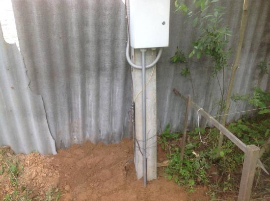
For re-grounding, I drove a corner 63x63 by 2m next to the pole and connected it to the existing one. History is silent about how deep the old corner is hammered.
Accordingly, the mounts were moved to a new corner.
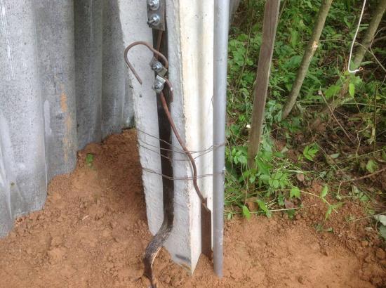


It remains to make a more or less normal fastening of the pipe to the pole and ground the shield door.
In the house, the cable will come to this switchboard:
And after it the main shield will be located.
Subsequently, additional grounding of the cabinet doors was made - both main and additional.