Star News


Schemes of automatic lighting switches. Automatic street lighting - Medium complexity designs - Schemes for beginners
The first of them (Fig. A-12) is made on four transistors. The light sensor - the sensitive element of the machine - is the photoresistor R1. It is connected to a power source through resistors R2 and R3 and together with them forms a voltage divider circuit, the resistance of one of the arms of which (from the trimmer resistor R2 to the negative power wire) changes depending on the illumination.
The voltage divider is connected to an emitter follower on the VT1 transistor, which allows you to match the relatively high resistance of the voltage divider with the low resistance of the subsequent stages of the machine.
A Schmitt trigger, made on transistors VT2, VT3, is connected to the load of the emitter follower (resistor R4). This is followed by a cascade on the transistor VT4 - a control signal amplifier. The emitter circuit of this transistor includes the control electrode of the trinistor VS1, which acts as a contactless switch - it controls the lighting lamp EL1, which is in the anode circuit of the trinistor.
The machine is powered from a 220 V network through a rectifier made on diodes VD2, VD3. The rectified voltage is filtered by capacitor C1 and stabilized by a silicon zener diode VD1. Capacitor C2 acts as a quenching resistor, on which the excess voltage drops.
If the illumination on the street is sufficient, the voltage at the output of the divider (resistor R2 engine), and hence at the output of the emitter follower, is such that the Schmitt trigger is in a steady state, in which the transistor VT2 is open and VT3 is closed. The transistor VT4 will also be closed, and therefore, there will be no voltage on the control electrode of the trinistor VS1 and the trinistor will also be closed. The lighting lamp is off.
With a decrease in illumination, the resistance of the photoresistor increases, the voltage at the output of the emitter follower decreases. When it reaches a certain value, the trigger will go into another stable state, in which the transistor VT2 is closed, and VT3 is open. In this case, the transistor VT4 will open and current will begin to flow through the control electrode of the trinistor. The trinistor will open, the lighting lamp will flash.
In the morning, when the illumination reaches the threshold value, the trigger returns to its original state and the lamp goes out.
The desired response threshold of the device is set by a tuning resistor R2.
With the details indicated in the diagram, a lamp with a power of up to 60 W can be connected to the machine. Instead of FS-K1, another photoresistor similar in parameters is quite applicable. Transistors VT1 - VT3 can be any of the MP39-MP42 series, but with a current transfer ratio of at least 50, and VT4 - any of the MP35-MP38 series with a current transfer ratio of at least 30. Instead of a Zener diode D814D, D813 is suitable, instead of diodes D226B - any other rectifiers, designed for a rectified current of at least 50 mA and a reverse voltage of at least 300 V.
Trimmer resistor R2 - SPZ-16, the remaining resistors - MLT-0.25. Capacitor C1 - K50-6, C2 - MBGO or other paper capacitor, designed for operation in AC and pulsating current circuits I and with a rated voltage not lower than that indicated in the diagram.
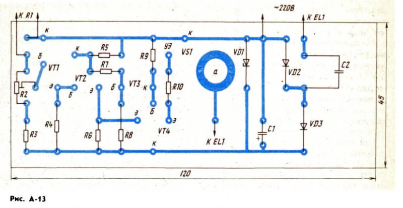
The details of the machine are mounted on a board (Fig. A-13) made of one-sided foil fiberglass. A hole is drilled under the trinistor in the board, around which the foil is left - it will be in contact with the case of the trinistor, which is the anode.
The conclusions of the cathode and the control electrode are located on top of the trinistor - they are connected by mounting conductors in insulation to the corresponding points of the printed circuit board. Capacitor C2 is attached to the board with screws (screw holes are not shown on the board).
The board is placed in a housing made of insulating material and connected by insulated mounting wires to a photoresistor, and by well-insulated network wires to a network and a lighting lamp. The photoresistor is fixed, for example, on a window, but in such a way that direct rays of the sun or light from street lamps do not fall on its sensitive layer.
And here is another design (Fig. A-14), containing only two transistors: field-effect VT1 and unijunction VT2. A pulse generator is made on a single-junction one, which turns on at a certain voltage at the emitter. And it, in turn, is determined by the illumination of the sensitive layer of the photoresistor R1.
On the field-effect transistor, a cascade is assembled, which contributes to a clearer "operation" of the generator. How this happens will become clear from the description of the operation of the machine. In the meantime, let's continue the story about the design of structures.
A trinistor control electrode is connected to one of the bases of the unijunction transistor, in the anode circuit of which there is an XS1 connector - a lighting lamp is turned on in it. The voltage to the trinistor and the lamp is supplied through a diode bridge, made up of diodes VD4 - VD7. Thanks to him, the trinistor is protected from reverse voltage at the anode.
A pulsating voltage (pulse frequency 100 Hz) is supplied through resistor R7 to the Zener diode VD3, which smooths out ripples due to its stabilizing property. Even more ripple of the rectified voltage is smoothed out by the capacitor C 4 - from it constant pressure fed to the circuit of the machine.
So, the machine is connected to the network, the photoresistor is directed by the photosensitive layer to the street. While it is light, the resistance of the photoresistor is small, which means that the voltage at the emitter of the unijunction transistor is also small. The generator does not work, the lighting pump does not light up.
As the illumination decreases, the resistance of the photoresistor increases, which means that the voltage at the emitter of the transistor VT2 also increases.
At a certain illumination of the photoresistor, its resistance becomes such that the generator starts to work. A pulsed voltage of positive polarity appears in resistor R6, which opens the trinistor and turns on the lamp. The pulse repetition rate is much higher than the ripple frequency of the supply voltage, so the trinistor opens almost at the beginning of each half-cycle of the mains voltage.
But what about the cascade on the transistor VT1? The very first pulses of the generator come from the resistor R6 through the capacitor C3 to the rectifier, assembled on the diodes VD1, VD2. As a result, a negative (with respect to the source) constant voltage appears on the load resistor R2, in other words, on the gate of the field-effect transistor VT1, which closes this transistor. The drain voltage increases, the voltage at the emitter of the unijunction transistor also increases. Due to this, the generator works more reliably and does not turn off even with some fluctuations in the illumination of the photoresistor.
In the morning, when dawn breaks and the illumination of the photoresistor increases, its resistance will drop so much that the generator will turn off. The lighting lamp will turn off. At this point, the transistor VT1 will open and further reduce the voltage at the emitter of the unijunction transistor.
Thus, thanks to the cascade on the transistor VT1, the thresholds for "activation" and "release" of the generator on the transistor VT2 are very clear and differ somewhat from each other in voltage.
The photoresistor can be FS-K1, SF2-5, SF2-6, fixed resistors - MLT-2 (R7) and MLT 0.125 or MLT-0.25 (the rest). Capacitors C1 - C3 - KLS, KM, MBM; C4 - K50-6 or K50-3. Instead of the KP3O3B transistor, KP3O3A is suitable, and instead of KT117B, another transistor of this series is suitable. Diodes VD1, VD2 - any of the series D2, D9, KD102, KD503; VD4 - VD7 - any rectifier with a permissible reverse voltage of at least 300 V and a rectified current that can power a lamp of a given power. Instead of the KS518A zener diode (it has a stabilization voltage of 18 V), you can use two zener diodes D814B or D814V connected in series. When using a lighting lamp with a power of 100 W, the trinistor can be indicated on the series diagram with letter indices K-N.

If a lamp with a power of up to 60 W is used, the trinistor KU201L or KU201M is suitable.
As in the previous machine, all parts, except for the photoresistor, are mounted on a printed circuit board (Fig. A-15) from one-sided foil fiberglass. The board is then reinforced in a housing made of insulating material. Recommendations for installing a photoresistor are the same as in the previous case.
When checking the machine, the required response threshold is more accurately set by selecting the resistor R3. Its resistance should not be less than 10 kOhm.
But not only for the staircase, an automatic light switch can be useful. It will also find application in an apartment, for example, in a bathroom or other room. And then you can be calm - it is unlikely that you will be able to leave aimlessly burning lights in these rooms. Yes, and now you don’t need to use the switch - the machine will completely replace it and will turn on the lighting itself when it is really needed.
A diagram of one of the options for such an automaton is shown in Fig. A-16. The machine turns on the lights as soon as the door is opened. If the door is locked from the inside, the light stays on. When the door is closed from the outside (or from the inside, but not for constipation), a time delay of 8 ... 10 s follows, after which the light goes out. The brightness of the light in this machine increases smoothly (for 1 ... 2 s), which significantly extends the life of the lamp.
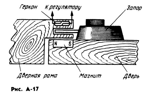
The device of the sensor that monitors the position of the door and its lock is shown in fig. A-17. A reed switch (sealed contact) is fixed in the door frame, and a permanent magnet is embedded in the door opposite it. The reed switch contacts are open when the door is open, which means the magnet is removed, and close when the door is closed due to the magnetic field of the permanent magnet. If the door is closed from the inside with a lock, its steel tongue (or an iron plate associated with it) shields the reed switch from the magnetic field and the reed switch contacts are open.
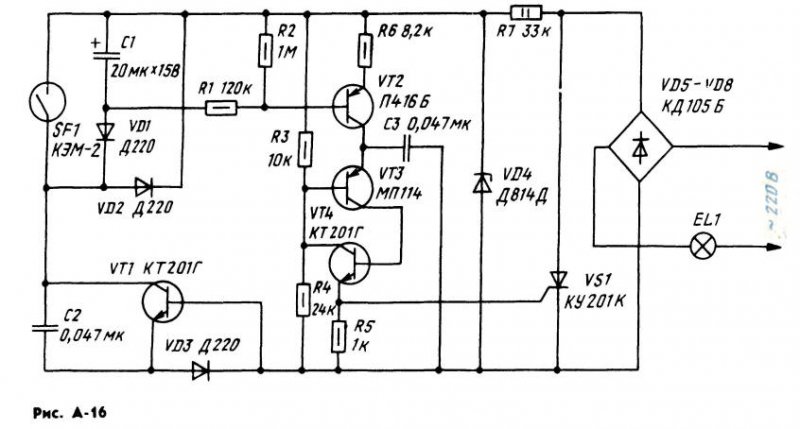
The reed switch (SF1 in the diagram) is included in the charging circuit of capacitor C1. If the door is open (or locked from the inside with a lock), the reed switch contacts are in the state shown in the diagram. Capacitor O begins to charge through the chain VD1, C2, VD3. Since the charging circuit is not powered direct current, and trapezoidal pulses of positive polarity (they are formed due to the limitation of the voltage pulses with a frequency of 100 Hz by the zener diode VD4, supplied to it through the resistor R7 from a full-wave rectifier on diodes VD5 - VD8), the capacitor C1 is charged "portions" from each pulse.
This mode is also ensured by the fact that by the time the next pulse begins, the capacitor C2 is discharged. This happens at the end of the previous pulse - then the voltage of the capacitor C2 is applied through the diode VD2 and resistors R3, R4 to the emitter junction of the transistor VT1. The transistor opens and discharges the capacitor. As the capacitor C1 is charging, the transistor VT2 begins to open, its collector current increases. At a certain value of this current, a pulse generator assembled on a transistor analog of a trinistor (transistors VT3 and VT4) and a capacitor C3 starts working. As soon as the voltage on the capacitor C3 (it appears as a result of charging the capacitor with the collector current of the transistor VT2) reaches the threshold, the analog of the trinistor "triggers" and the capacitor is discharged through the control electrode of the trinistor VS1 and resistor R5. The trinistor opens (and remains open until the end of the half-cycle of the mains voltage), closes the diagonal of the bridge VD5 - VD8, and the EL1 lamp lights up. Its brightness depends on the duration of the charging of the SZ capacitor to the "operation" voltage of the SCR analog.
The duration, in turn, is determined by the collector current of the transistor VT2, and hence by charging the capacitor C1 to the full opening voltage of the transistor VT2. This happens after about 1 ... 2 s - during this time, the brightness of the lamp will increase to maximum.
It is worth closing the door (or do not close the lock when the door is closed) - and the closed contacts of the reed switch will bypass the charging circuit of capacitor C1. It will start to discharge through the resistors R1, R6 and the emitter junction of the transistor VT2. After 8 ... 10 s, the voltage across the capacitor will drop so much that the transistor VT2 will start to close. The brightness of the lamp will gradually decrease, and then the lamp will turn off.
In addition to that indicated in the diagram, trinistors KU201 L, KU202K-KU202N can be used. KT201G transistors are interchangeable with a transistor of the same series or with any transistors of the KT315 series; P416B - on P416 P401-P403, GT308; MP114 - ng MP115, MP116, KT203. Together with diodes D220, D223, KD102, KD103 are suitable. Capacitor C1 - K50-6; C2, NW - MBM, KM-4, KM-5. Resistor R7 - MLT-2, the rest - MLT-0.5. Instead of a D814D zener diode, D813 is suitable, and instead of VD5-VD8 diodes, any rectifier diodes designed for a reverse voltage of at least 300 V and a rectified current of at least 300 mA. Reed switch - any other with normally open contacts and "operating" from a given permanent magnet at a given distance.
The parts of the machine can be mounted on a printed circuit board (Fig. A-18) made of foil material and the board can be reinforced in any suitable case made of insulating material. It is desirable to place the case near the switch so that the connecting conductors from the diode bridge are shorter - they are connected to the contacts of the mains switch, and the switch handle is set to the "Off" position. The conclusions of the reed switch are connected to the machine with stranded mounting conductors in insulation.
As a rule, the machine does not require adjustment and starts working immediately. You can change the duration of a smooth increase in the brightness of light by selecting capacitor C2 (with a decrease in its capacitance, the duration of the increase in brightness increases). To change the delay of turning off the light, you should select the capacitor C1 (the delay increases with an increase in its capacitance).


The machine is able to control a lamp with a power of 60 watts. If a higher power lamp is used, it is necessary to install a trinistor on a heat sink and assemble a diode rectifier with a large allowable rectified current.
And here is another machine (Fig. A-19) for a similar purpose, which uses only one transistor. The machine can also be connected in parallel with the terminals of switch Q1 in the utility room.
The controls of the machine are the switch SA1, the contacts of which form an external latch and bracket on the door frame, and the reed switch SF1, installed on the door similarly to the previous version, but in the upper corner of the door frame. When the door is closed, contacts SA1 can be both closed and open (if the room is in use and the shutter is open), and contacts SF1 can only be open. When the door is opened, the switch contacts are open, and the reed switch contacts are closed. Through the resistor R2 and the reed switch, voltage is applied to the control electrode of the tri-nistor VS1. The trinistor opens, the lighting lamp EL1 lights up.
At this moment, a pulsating voltage appears on the resistor R1 (with an amplitude of about 1 V with a lamp power of 40 W and almost 2 V with a lamp power of 100 W). It is smoothed by the VD2C1 chain. G capacitor C1 DC voltage is supplied to the generator, assembled on the transistor VT1. The pulse repetition rate of the generator is 3 kHz. From the winding 111 of the transformer T1, the pulses are fed to the control electrode of the trinistor, so the trinistor remains open after the door is closed from inside the room and the reed switch contacts are opened.
At the end of the use of the premises, the door is closed to the external latch, the contacts SA1 close and shunt the winding II of the transformer. The oscillations of the generator break down, the trinistor closes, the lighting lamp goes out.
Any low-power germanium transistor can work in the generator pnp structures with a static current transfer ratio of at least 50. Instead of the diode bridge VD1, you can install four diodes KD105B-KD105G or similar in terms of rectified current and reverse voltage. Trinistor - KU201 series with letter indices K-N. Capacitor O -K50-12 (K50-6 is also suitable); C2 - MBM; resistors - MLT-2.
The T1 transformer is self-made, it is made on a K10X6X4 size ring made of M200NM ferrite. Winding I contains 2XO0 turns of wire PELSHO 0.1, winding II - 6 ... 10 turns of thin mounting wire in PVC insulation, winding III - 40 turns PELSHO 0.1.
A printed circuit board (Fig. A-20) made of one-sided foil fiberglass is designed for these parts. Printed conductors are not made by etching in a solution, as is usually done, but by cutting insulating grooves in the foil with a special cutter or a sharp knife. The board with the parts is strengthened in the case, which is placed in a convenient place in the room. As in the previous case, the reed switch (it can be any, but always with normally closed or switching contacts) is connected to the machine with stranded mounting conductors.
If the machine is mounted without errors, no adjustment is needed. It may happen that the generator is not excited with a given lighting lamp (after all, the generator supply voltage depends on its power). Then you will either have to put a resistor R1 with a large resistance, or another transistor with a large transfer coefficient.
In the case of normal operation of the generator and a non-opening trinistor (the light goes out when the door is closed, but the SA1 contacts are not closed), it is necessary to change the polarity of the connection of the terminals of the winding III.
This device based on a light sensor and an IR sensor allows you to automate the process of lighting switching, which leads to energy savings.
Rice. 1 Scheme of automatic lighting
Figure 1 shows a diagram of a lighting machine. The core of the circuit is the PIC16F628A microcontroller. The diagram for connecting the load in the form of a lamp is shown in Figure 2. Figure 3 shows the structure of the device. The algorithm for controlling the device using the button is shown in Figure 4. The program code is written in assembly language, see listing AL \ 16F628ATEMP.ASM. The device is controlled by one button. Pressing the button achieves a sequential change in the operating modes of the device. A display with a built-in controller is used for visual display of information.
Rice. 2 Load connection diagram in the form of a lamp
A full cycle of in-circuit programming and debugging of the PIC16F628A microcontroller was carried out using MPLAB IDE v8.15 (integrated development environment), MPASM v5.22 compiler (included in MPLAB IDE v8.15) and MPLAB ICD 2 (in-circuit debugger - "Debugger"). For those who do not have the above tools, but have their own program for working with HEX files and another programmer, you can find the 16F628ATEMP.HEX file in the corresponding project. The technical specification of the microcontroller can be found on the website and.
Rice. 3 Device structure
The DD1 microcontroller has functional outputs RA0, AN1, VREF, RA3, RB0 - RB7, CCP1, which are used to input and output information. The DD1 microcontroller does not have a forced reset function, the reset pin is connected through a resistor R6 to the positive power potential. An on-chip RC oscillator is used to generate the clock frequency.
Rice. 4 Algorithm for controlling the device using a button
With the help of integrated comparators (in this case, one is used) and ION in the microcontroller, the possibility of step-by-step voltage measurement on a conditional 17-point scale is implemented. A photoresistor R1 and a resistor R2 are connected to the comparator input AN1. The second input of the comparator is connected to ION - VREF. With step-by-step adjustment of the ION from 1.25 V to 3.594 V, the voltage is compared between R1, R2 and VREF. Set to 00 - (V → 0V, 1.25V], set to 01 to 15 - (1.25V, 3.594V], set to 16 - (3.594V, V → 5V). Where V is the potential between R1 and R2 (i.e. on AN1).
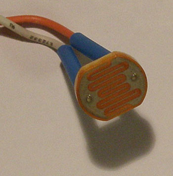
Photo 1
It should be noted that the light sensor (photoresistor) is connected to the device through the XS1 socket and the XP1 plug. (Photo 1) The light sensor should be placed near a window (source of natural light). It will be better if the light-sensitive part of the light sensor is pointed at the window sill or wall, to measure not direct rays from the sun or a light source, but reflected ones.
When setting the device in the dark, the threshold voltage value is measured at which the light turns on, the display shows information about the setting "D", D - Dark. When setting up the device during daylight hours, the threshold voltage value is measured at which the light turns off, the display shows information about the setting "L", L - Light. Values in the dark time of the day should be less than in the daytime. From the described example of setting the light sensor, it follows that the logical "1" will be when the measured conditional value of the illumination takes on a value from 00 to 02, and the logical "0" - from 12 to 16. With intermediate values from 03 to 11, the device does not change the logic of the light sensor , this is necessary so that the lighting device, which, when turned on, added illumination in the room, does not affect the logic and vice versa, i.e. when the lighting fixture is turned off.
The IR sensor consists of an IR emitter (IR diode) and an IR receiver, they are connected to the device via an XS2 socket and an XP2 plug and are used for non-contact detection of body movements. (Photo 2)
An IR receiver is connected to the output RA0 through a current-limiting resistor R4 DA1. In the passive state of the information input circuit, resistor R3 simulates a low logic level.
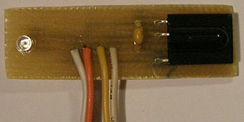
Photo 2
The gate of the field-effect transistor VT1 is connected to the output of CCP1 (hardware implementation of PWM, frequency 38.15 kHz, duty cycle 2), which generates the carrier frequency of the IR emitter. An IR diode with a wavelength of 940 nm is connected to the drain of the field-effect transistor VT1 through a current-limiting resistor R5.
Since the IR sensor works on reflection, it sets the logical "1" when the IR receiver DA1 detects the beam of the IR diode VD1 reflected from the body, otherwise the logical "0" is set.
To expand the capabilities of the device during detection by the IR sensor, it is possible to hold the logical level set by the IR sensor for a certain time (keep logic "1"). For this, the P[x], P-Pause function is used.
- P[D]* – logic level set by the IR sensor after detection is held for 1 second. Therefore, the possible detection sequence is 1 second or more.
- P[E]** – the logical level set by the IR sensor after detection is held for 1 minute. Therefore, the possible detection sequence is 1 minute or more.
In order for the logic change formed by the IR sensor to set two stable states in turn, the trigger function T[x], T-Trigger is implemented. For example, if you install an IR sensor in the doorway, the passage of a person between rooms will be recorded. Thus, when entering the room, a logical "1" is set (the lighting device turns on), when leaving, a logical "0" is set (the lighting device turns off). It makes no sense to turn on the trigger when several people are moving around the room.
- T[D]* – trigger disabled.
- T[E]** – trigger enabled.
To compare the logical states from the light sensor and the IR sensor, use the F, F-Function. The function can take four values.
- F-function disabled. The logic data from the ambient light sensor and the IR sensor do not affect the dongle. You can only switch the load manually by inverting the logic at the RB2 output by briefly pressing the SB1 button.
- F - "OR" function, the result of a logical operation is formed at the output RB2 ***.
- F - "XOR" function, the result of a logical operation is formed at the output RB2 ***.
- F- function "AND", the result of a logical operation is formed at the output RB2 ***.
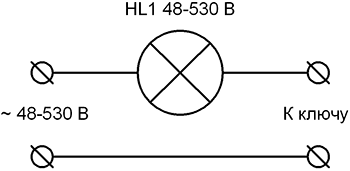
By forming logic at the RB2 output, they achieve the opening or closing of the solid state relay U1, which turns on and off the lighting device connected to the X1 terminal block. The solid state relay U1 can switch the load when AC voltage 48-530 V and a maximum current of 3 A (the operating temperature of the solid state relay U1 must not exceed +60 °C). The logic level at the RB2 pin is shown on the display, K[x], K-Key.
- K[D]* - logical "0", the key is off (lighting device is off).
- K[E]**- logical "1", the key is on (lighting device is on).
*x[D], D-Disable.
**x[E], E-Enable.
*** It is worth paying attention to the fact that you can invert the logic at the RB2 pin by forcibly pressing the SB1 button for a short time. After pressing the SB1 button, the changed logic on RB2 is held until it is equal to the function logic, then the device sets the logic level generated by the function, i.e. switches to the normal mode of operation (which was before a short press of the button).
The clock button SB1 is connected to the output RA3 through the current-limiting resistor R11. In the depressed position of the clock button SB1, the resistor R12 simulates a low logic level. The DD1 microcontroller recognizes three states of the SB1 clock button:
- not pressed;
- pressed briefly (less than 1 s);
- pressed and held (more than 1 s).
The image on the display helps to distinguish the state of the tact button SB1. So at state 1, the microcontroller executes instructions not related to pressing a button, at state 2, settings are performed, which are highlighted in square brackets until the microcontroller recognizes state 3, and in state 3, the display shows the next customizable state in square brackets.
To display information, a liquid crystal display HG1 is used. The technical specification of the display can be found on the website. It has a controller that implements the character generation function. Displays two lines of sixteen characters each. The display is controlled through the microcontroller pins RB0, RB1, RB4 - RB7. Data is loaded in nibbles, through pins RB4 - RB7. "Latch" - RB1. The choice of the signal register is formed at the output RB0. Resistors R7 and R8 set the contrast of the display HG1. The backlight of the display is powered through a current-limiting resistor R9. The HG1 display is screwed to the board with 3 x 15 mm brass standoffs and 3 x 6 mm screws.
The device is powered by an AC or DC voltage source connected to connector X2. The rated voltage of the power supply is 9 - 15 V. The rated current of the power supply is 1 A. To stabilize the power supply, a conventional circuit is used from a diode bridge VD2, a linear stabilizer DA2, filter capacitors C1 - C6.
The device can be operated in the temperature range from -20 °С to +60 °С.
The microcontroller is programmed in such a way that it has seven operating states.
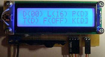
Photo 3

Photo 4

Photo 5

Photo 6
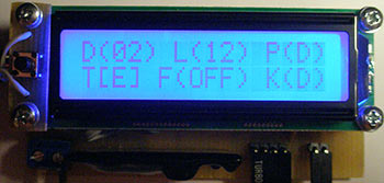
Photo 7

Photo 8
- When the device is turned on, the non-volatile data memory EEPROM is read, where the settings data is unloaded (by default D(00), L(16), P(D), T(D), F(OFF), K[D]). The device enters the main operating state, i.e. 2.
- The device displays on the display the area allocated by square brackets over which it works. In this case, it's the key. In addition, the device performs configured functions that lead to switching the key. During operation, the display shows the state of the key (K[D]-off, K[E]-on) ****. After briefly pressing the clock button, the device forcibly inverts the logic of the key and holds it until the set logic level equals the logic level as a result of the execution of the logic function. If the tact button is pressed and held for more than 1 s, the device switches to the state where the light sensor is adjusted in the dark, i.e. 3. (Photo 3)
- The device displays on the display the area allocated by square brackets over which it works. In this case, this is the setting of the light sensor in the dark. After briefly pressing the tact button, the device measures the level of illumination and displays it on the display. If the tact button is pressed and held for more than 1 s, the device switches to the state where the light sensor is adjusted during daylight hours, i.e. 4. (Photo 4)
- The device displays on the display the area allocated by square brackets over which it works. In this case, this is the setting of the light sensor during daylight hours. After briefly pressing the tact button, the device measures the level of illumination and displays it on the display. If the tact button is pressed and held for more than 1 s, the device switches to the state where the IR sensor logic pause is configured, i.e. 5. (Photo 5)
- The device displays on the display the area allocated by square brackets over which it works. In this case, it is the IR sensor logic pause setting. After a short press of the tact button, the device turns on or off the pause of the IR sensor logic. If the tact button is pressed and held for more than 1 s, the device switches to the state where the IR sensor trigger is configured, i.e. 6. (Photo 6)
- The device displays on the display the area allocated by square brackets over which it works. In this case, it is the IR sensor trigger setting. After a short press of the tact button, the device turns on or off the IR sensor trigger. If the tact button is pressed and held for more than 1 s, then the device switches to the state where the logical function is configured, i.e. 7. (Photo 7)
- The device displays on the display the area allocated by square brackets over which it works. In this case, it is the setting of the logic function. After briefly pressing the tact button, the device sequentially selects the logic function. If the tact button is pressed and held for more than 1 s, the device saves the settings in non-volatile EEPROM memory and switches to the main operating state, i.e. 2. (Photo 8)
****When the device is turned on, the key state is indicated as inactive (K[D]) even if the key is turned on until the logic changes as a result of a logical operation or a short press of a button (of course, this can be considered as a flaw, but how the device works).
See the files for the manufacture of printed circuit boards in the folder. The printed circuit board and the location of parts are shown in Figure 5.
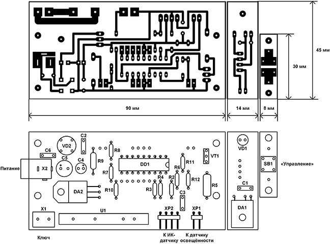
Fig.5 PCB and parts layout
The following parts can be replaced on this unit. Microcontroller DD1 from the PIC16F628A-I / P-xxx series with an operating clock frequency of 20 MHz in a DIP18 package. The HG1 display will fit any of the WH1602x series. Photoresistor R1 similar to that indicated in the diagram, when selecting resistor R2, its resistance should be no more than 10 kOhm. IR receiver DA1 detecting the carrier frequency of the IR beam 38 kHz TSOP31238.
Voltage stabilizer DA2 domestic KR142EN5A (5 V, 1.5 A). Field MOSFET transistor VT1 (N-channel) in the I-Pak package (TO-251AA), an analog of the rating indicated on the diagram is suitable. Solid state relay U1 can be found similar in extreme cases, replaced by CX240D5 with other characteristics. IR diode VD1 with a wavelength of 940 - 960 nm. Diode bridge VD2 can be applied to any of the 2Wxx series. Angled plugs XP1 and XP2 with 2.54 mm pin spacing. Power connector X2 similar to that shown in the diagram with a central contact d=2.1 mm. Non-polar capacitors C1-C3 and C6 with a rating of 0.01 - 0.47 µF x 50 V. Electrolytic capacitors C4 and C5 have the same capacitive rating, and the voltage is not lower than that indicated in the diagram.
Below you can download the asm source code, firmware and circuit board in the format
List of radio elements
| Designation | Type of | Denomination | Quantity | Note | Score | My notepad |
|---|---|---|---|---|---|---|
| DD1 | MK PIC 8-bit | PIC16F628A | 1 | Search in LCSC | To notepad | |
| DA1 | IR receiver | TSOP1738 | 1 | Search in LCSC | To notepad | |
| DA2 | Linear Regulator | LM7805A | 1 | Search in LCSC | To notepad | |
| VT1 | MOSFET transistor | IRLU024N | 1 | Search in LCSC | To notepad | |
| VD2 | Diode bridge | 2W10 | 1 | Search in LCSC | To notepad | |
| C1-C3, C6 | Capacitor | 0.1uF | 4 | Search in LCSC | To notepad | |
| C4 | 100uF 10V | 1 | Search in LCSC | To notepad | ||
| C5 | electrolytic capacitor | 220uF 25V | 1 | Search in LCSC | To notepad | |
| R1 | VT43N3 | 1 | Search in LCSC | To notepad | ||
| R2, R12 | Resistor | 4.7 kOhm | 2 | Search in LCSC | To notepad | |
| R3, R6, R7 | Resistor | 10 kOhm | 3 | Search in LCSC | To notepad | |
| R4, R11 | Resistor | 470 ohm | 2 | Search in LCSC | To notepad | |
| R5 | Resistor | 43 ohm | 1 | 1 W |
Outdoor bathroom lighting control.
Somehow, while connecting an LED strip to a friend, we talked about lighting, and then he remembered that he had no light in the street bathroom.
Everything would be fine, but sometimes we go to visit him with beer, relax in the gazebo, admire nature, talk about high things. And as you know, not all people in the dark have good aiming skills and a sniper's intuition. Therefore, regularly after our visit, he has to wash the bathroom.
So he puzzled me with the assembly of a kind of automatic lighting from two dead Chinese lanterns (two LEDs each), and a swollen battery from Nokia (in my opinion, 1200mAh). We couldn't find anything else suitable in his house.
The device algorithm was initially assumed to be quite simple:
The door is open, the light is on
The door was closed, the light went out
Reed switch, mosfet - that's business! But then it turned out that he had a serious flaw! Let's say you went into the bathroom, sat down or steel, closed the door, the light went out. It doesn't work well with the door open. I immediately imagined a microcontroller, a circuit diagram, a program ... but then a toad crushed me to use a microcontroller for these purposes, which I had left in a single copy. In 5 minutes, a circuit was drawn on a piece of paper on 2 transistors, and the following algorithm was obtained:
Opened the door, the light came on
Closed the door, the light is on for 1.5 minutes, and then slowly goes out.
If the door is open all the time, the light stays on all the time.
I think in 1.5 minutes you can do whatever you want there, and if anyone really wants to read a newspaper, you can simply “distort” the door in 1.5 minutes, and the light will turn on again.
“Now we need to assemble a layout on snot, and select the denominations of parts,” I thought. Then I remembered that I have a Proteus simulator !! For 10 minutes, the necessary denominations of parts were selected, and the following scheme was obtained.
In fact, the circuit is the simplest single vibrator on two transistors. As a door opening sensor, a reed switch is used, torn out of some very old glass-break sensor, and the sensor was honestly “communized” somewhere, anyway it would be thrown into the trash. When the bathroom door is closed, the magnet is next to the reed switch. The contacts of the reed switch are closed. Transistor Q1, Q2 are closed, capacitor C1 is discharged, LEDs D6-D4 do not light up.
When the door is opened, the reed switch contacts open, the transistor Q1 opens, the capacitor C1 is charged through the diode D1, Q2 opens and the LEDs light up.

If the reed switch contacts remain open, then the transistors Q1, Q2 are open, and the light is constantly on. As soon as the door is closed, the contacts of the reed switch are closed, the discharge of C1 through the resistor R1 will begin, after about 1.5 minutes the transistor Q2 will start to smoothly cover itself, and accordingly the light will go out until Q2 is completely closed. In order to increase the glow time, you can replace the diode D1 with a Schottky diode, increase the value of the capacitor C1, in case of too long charging C1, select the values R7, R8, R6. The most important thing is that there should be a minimum battery discharge current in standby mode, in this case 2mkA.
In general - we take Proteus and torture the scheme.
Resistors R3-R5 are inside Chinese lanterns. Transistor Q2 STD17NF03 is soldered from an ancient motherboard, you can use any n channel mosfet. Because this one seems to be at 17A, and in the bathroom you can power a couple of hundred LEDs.
That's the kind of electronics in everyday life. The battery, after it sits down, is inserted into the phone, charged and put back in place. Huge savings on batteries. Saved money goes to beer.
The first of them (Fig. A-12) is made on four transistors. The light sensor - the sensitive element of the machine - is the photoresistor R1. It is connected to a power source through resistors R2 and R3 and together with them forms a voltage divider circuit, the resistance of one of the arms of which (from the trimmer resistor R2 to the negative power wire) changes depending on the illumination.
The voltage divider is connected to an emitter follower on the VT1 transistor, which allows you to match the relatively high resistance of the voltage divider with the low resistance of the subsequent stages of the machine.
A Schmitt trigger, made on transistors VT2, VT3, is connected to the load of the emitter follower (resistor R4). This is followed by a cascade on the transistor VT4 - a control signal amplifier. The emitter circuit of this transistor includes the control electrode of the trinistor VS1, which acts as a contactless switch - it controls the lighting lamp EL1, which is in the anode circuit of the trinistor.
The machine is powered from a 220 V network through a rectifier made on diodes VD2, VD3. The rectified voltage is filtered by capacitor C1 and stabilized by a silicon zener diode VD1. Capacitor C2 acts as a quenching resistor, on which the excess voltage drops.
If the illumination on the street is sufficient, the voltage at the output of the divider (resistor R2 engine), and hence at the output of the emitter follower, is such that the Schmitt trigger is in a steady state, in which the transistor VT2 is open and VT3 is closed. The transistor VT4 will also be closed, and therefore, there will be no voltage on the control electrode of the trinistor VS1 and the trinistor will also be closed. The lighting lamp is off.
With a decrease in illumination, the resistance of the photoresistor increases, the voltage at the output of the emitter follower decreases. When it reaches a certain value, the trigger will go into another stable state, in which the transistor VT2 is closed, and VT3 is open. In this case, the transistor VT4 will open and current will begin to flow through the control electrode of the trinistor. The trinistor will open, the lighting lamp will flash.
In the morning, when the illumination reaches the threshold value, the trigger returns to its original state and the lamp goes out.
The desired response threshold of the device is set by a tuning resistor R2.
With the details indicated in the diagram, a lamp with a power of up to 60 W can be connected to the machine. Instead of FS-K1, another photoresistor similar in parameters is quite applicable. Transistors VT1 - VT3 can be any of the MP39-MP42 series, but with a current transfer ratio of at least 50, and VT4 - any of the MP35-MP38 series with a current transfer ratio of at least 30. Instead of a Zener diode D814D, D813 is suitable, instead of diodes D226B - any other rectifiers, designed for a rectified current of at least 50 mA and a reverse voltage of at least 300 V.
Trimmer resistor R2 - SPZ-16, the remaining resistors - MLT-0.25. Capacitor C1 - K50-6, C2 - MBGO or other paper capacitor, designed for operation in AC and pulsating current circuits I and with a rated voltage not lower than that indicated in the diagram.
The details of the machine are mounted on a board (Fig. A-13) made of one-sided foil fiberglass. A hole is drilled under the trinistor in the board, around which the foil is left - it will be in contact with the case of the trinistor, which is the anode.
The conclusions of the cathode and the control electrode are located on top of the trinistor - they are connected by mounting conductors in insulation to the corresponding points of the printed circuit board. Capacitor C2 is attached to the board with screws (screw holes are not shown on the board).
The board is placed in a housing made of insulating material and connected by insulated mounting wires to a photoresistor, and by well-insulated network wires to a network and a lighting lamp. The photoresistor is fixed, for example, on a window, but in such a way that direct rays of the sun or light from street lamps do not fall on its sensitive layer.
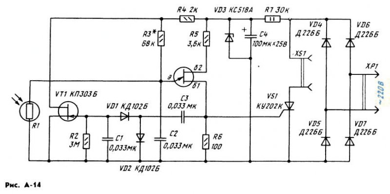
And here is another design (Fig. A-14), containing only two transistors: field-effect VT1 and unijunction VT2. A pulse generator is made on a single-junction one, which turns on at a certain voltage at the emitter. And it, in turn, is determined by the illumination of the sensitive layer of the photoresistor R1.
On the field-effect transistor, a cascade is assembled, which contributes to a clearer "operation" of the generator. How this happens will become clear from the description of the operation of the machine. In the meantime, let's continue the story about the design of structures.
A trinistor control electrode is connected to one of the bases of the unijunction transistor, in the anode circuit of which there is an XS1 connector - a lighting lamp is turned on in it. The voltage to the trinistor and the lamp is supplied through a diode bridge, made up of diodes VD4 - VD7. Thanks to him, the trinistor is protected from reverse voltage at the anode.
A pulsating voltage (pulse frequency 100 Hz) is supplied through resistor R7 to the Zener diode VD3, which smooths out ripples due to its stabilizing property. Even more ripple of the rectified voltage is smoothed out by the capacitor C 4 - from it a constant voltage is supplied to the circuits of the machine.
So, the machine is connected to the network, the photoresistor is directed by the photosensitive layer to the street. While it is light, the resistance of the photoresistor is small, which means that the voltage at the emitter of the unijunction transistor is also small. The generator does not work, the lighting pump does not light up.
As the illumination decreases, the resistance of the photoresistor increases, which means that the voltage at the emitter of the transistor VT2 also increases.
At a certain illumination of the photoresistor, its resistance becomes such that the generator starts to work. A pulsed voltage of positive polarity appears in resistor R6, which opens the trinistor and turns on the lamp. The pulse repetition rate is much higher than the ripple frequency of the supply voltage, so the trinistor opens almost at the beginning of each half-cycle of the mains voltage.
But what about the cascade on the transistor VT1? The very first pulses of the generator come from the resistor R6 through the capacitor C3 to the rectifier, assembled on the diodes VD1, VD2. As a result, a negative (with respect to the source) constant voltage appears on the load resistor R2, in other words, on the gate of the field-effect transistor VT1, which closes this transistor. The drain voltage increases, the voltage at the emitter of the unijunction transistor also increases. Due to this, the generator works more reliably and does not turn off even with some fluctuations in the illumination of the photoresistor.
In the morning, when dawn breaks and the illumination of the photoresistor increases, its resistance will drop so much that the generator will turn off. The lighting lamp will turn off. At this point, the transistor VT1 will open and further reduce the voltage at the emitter of the unijunction transistor.
Thus, thanks to the cascade on the transistor VT1, the thresholds for "activation" and "release" of the generator on the transistor VT2 are very clear and differ somewhat from each other in voltage.
The photoresistor can be FS-K1, SF2-5, SF2-6, fixed resistors - MLT-2 (R7) and MLT 0.125 or MLT-0.25 (the rest). Capacitors C1 - C3 - KLS, KM, MBM; C4 - K50-6 or K50-3. Instead of the KP3O3B transistor, KP3O3A is suitable, and instead of KT117B, another transistor of this series is suitable. Diodes VD1, VD2 - any of the series D2, D9, KD102, KD503; VD4 - VD7 - any rectifier with a permissible reverse voltage of at least 300 V and a rectified current that can power a lamp of a given power. Instead of the KS518A zener diode (it has a stabilization voltage of 18 V), you can use two zener diodes D814B or D814V connected in series. When using a lighting lamp with a power of 100 W, the trinistor can be indicated on the series diagram with letter indices K-N.
If a lamp with a power of up to 60 W is used, the trinistor KU201L or KU201M is suitable.
As in the previous machine, all parts, except for the photoresistor, are mounted on a printed circuit board (Fig. A-15) from one-sided foil fiberglass. The board is then reinforced in a housing made of insulating material. Recommendations for installing a photoresistor are the same as in the previous case.
When checking the machine, the required response threshold is more accurately set by selecting the resistor R3. Its resistance should not be less than 10 kOhm.
But not only for the staircase, an automatic light switch can be useful. It will also find application in an apartment, for example, in a bathroom or other room. And then you can be calm - it is unlikely that you will be able to leave aimlessly burning lights in these rooms. Yes, and now you don’t need to use the switch - the machine will completely replace it and will turn on the lighting itself when it is really needed.
A diagram of one of the options for such an automaton is shown in Fig. A-16. The machine turns on the lights as soon as the door is opened. If the door is locked from the inside, the light stays on. When the door is closed from the outside (or from the inside, but not for constipation), a time delay of 8 ... 10 s follows, after which the light goes out. The brightness of the light in this machine increases smoothly (for 1 ... 2 s), which significantly extends the life of the lamp.
The device of the sensor that monitors the position of the door and its lock is shown in fig. A-17. A reed switch (sealed contact) is fixed in the door frame, and a permanent magnet is embedded in the door opposite it. The reed switch contacts are open when the door is open, which means the magnet is removed, and close when the door is closed due to the magnetic field of the permanent magnet. If the door is closed from the inside with a lock, its steel tongue (or an iron plate associated with it) shields the reed switch from the magnetic field and the reed switch contacts are open.
The reed switch (SF1 in the diagram) is included in the charging circuit of capacitor C1. If the door is open (or locked from the inside with a lock), the reed switch contacts are in the state shown in the diagram. Capacitor O begins to charge through the chain VD1, C2, VD3. Since the charging circuit is not powered by direct current, but by trapezoidal pulses of positive polarity (they are formed due to the limitation of the voltage pulses with a frequency of 100 Hz by the zener diode VD4, supplied to it through the resistor R7 from a full-wave rectifier on diodes VD5 - VD8), the capacitor C1 is charged in "portions" from every impulse.
This mode is also ensured by the fact that by the time the next pulse begins, the capacitor C2 is discharged. This happens at the end of the previous pulse - then the voltage of the capacitor C2 is applied through the diode VD2 and resistors R3, R4 to the emitter junction of the transistor VT1. The transistor opens and discharges the capacitor. As the capacitor C1 is charging, the transistor VT2 begins to open, its collector current increases. At a certain value of this current, a pulse generator assembled on a transistor analog of a trinistor (transistors VT3 and VT4) and a capacitor C3 starts working. As soon as the voltage on the capacitor C3 (it appears as a result of charging the capacitor with the collector current of the transistor VT2) reaches the threshold, the analog of the trinistor "triggers" and the capacitor is discharged through the control electrode of the trinistor VS1 and resistor R5. The trinistor opens (and remains open until the end of the half-cycle of the mains voltage), closes the diagonal of the bridge VD5 - VD8, and the EL1 lamp lights up. Its brightness depends on the duration of the charging of the SZ capacitor to the "operation" voltage of the SCR analog.
The duration, in turn, is determined by the collector current of the transistor VT2, and hence by charging the capacitor C1 to the full opening voltage of the transistor VT2. This happens after about 1 ... 2 s - during this time, the brightness of the lamp will increase to maximum.
It is worth closing the door (or do not close the lock when the door is closed) - and the closed contacts of the reed switch will bypass the charging circuit of capacitor C1. It will start to discharge through the resistors R1, R6 and the emitter junction of the transistor VT2. After 8 ... 10 s, the voltage across the capacitor will drop so much that the transistor VT2 will start to close. The brightness of the lamp will gradually decrease, and then the lamp will turn off.
In addition to that indicated in the diagram, trinistors KU201 L, KU202K-KU202N can be used. KT201G transistors are interchangeable with a transistor of the same series or with any transistors of the KT315 series; P416B - on P416 P401-P403, GT308; MP114 - ng MP115, MP116, KT203. Together with diodes D220, D223, KD102, KD103 are suitable. Capacitor C1 - K50-6; C2, NW - MBM, KM-4, KM-5. Resistor R7 - MLT-2, the rest - MLT-0.5. Instead of a D814D zener diode, D813 is suitable, and instead of VD5-VD8 diodes, any rectifier diodes designed for a reverse voltage of at least 300 V and a rectified current of at least 300 mA. Reed switch - any other with normally open contacts and "operating" from a given permanent magnet at a given distance.
The parts of the machine can be mounted on a printed circuit board (Fig. A-18) made of foil material and the board can be reinforced in any suitable case made of insulating material. It is desirable to place the case near the switch so that the connecting conductors from the diode bridge are shorter - they are connected to the contacts of the mains switch, and the switch handle is set to the "Off" position. The conclusions of the reed switch are connected to the machine with stranded mounting conductors in insulation.
As a rule, the machine does not require adjustment and starts working immediately. You can change the duration of a smooth increase in the brightness of light by selecting capacitor C2 (with a decrease in its capacitance, the duration of the increase in brightness increases). To change the delay of turning off the light, you should select the capacitor C1 (the delay increases with an increase in its capacitance).
The machine is able to control a lamp with a power of 60 watts. If a higher power lamp is used, it is necessary to install a trinistor on a heat sink and assemble a diode rectifier with a large allowable rectified current.
And here is another machine (Fig. A-19) for a similar purpose, which uses only one transistor. The machine can also be connected in parallel with the terminals of switch Q1 in the utility room.
The controls of the machine are the switch SA1, the contacts of which form an external latch and bracket on the door frame, and the reed switch SF1, installed on the door similarly to the previous version, but in the upper corner of the door frame. When the door is closed, contacts SA1 can be both closed and open (if the room is in use and the shutter is open), and contacts SF1 can only be open. When the door is opened, the switch contacts are open, and the reed switch contacts are closed. Through the resistor R2 and the reed switch, voltage is applied to the control electrode of the tri-nistor VS1. The trinistor opens, the lighting lamp EL1 lights up.
At this moment, a pulsating voltage appears on the resistor R1 (with an amplitude of about 1 V with a lamp power of 40 W and almost 2 V with a lamp power of 100 W). It is smoothed by the VD2C1 chain. G capacitor C1 DC voltage is supplied to the generator, assembled on the transistor VT1. The pulse repetition rate of the generator is 3 kHz. From the winding 111 of the transformer T1, the pulses are fed to the control electrode of the trinistor, so the trinistor remains open after the door is closed from inside the room and the reed switch contacts are opened.
At the end of the use of the premises, the door is closed to the external latch, the contacts SA1 close and shunt the winding II of the transformer. The oscillations of the generator break down, the trinistor closes, the lighting lamp goes out.
Any low-power p-n-p germanium transistor with a static current transfer coefficient of at least 50 can work in the generator. Trinistor - KU201 series with letter indices K-N. Capacitor O -K50-12 (K50-6 is also suitable); C2 - MBM; resistors - MLT-2.
The T1 transformer is self-made, it is made on a K10X6X4 size ring made of M200NM ferrite. Winding I contains 2XO0 turns of wire PELSHO 0.1, winding II - 6 ... 10 turns of thin mounting wire in PVC insulation, winding III - 40 turns PELSHO 0.1.
A printed circuit board (Fig. A-20) made of one-sided foil fiberglass is designed for these parts. Printed conductors are not made by etching in a solution, as is usually done, but by cutting insulating grooves in the foil with a special cutter or a sharp knife. The board with the parts is strengthened in the case, which is placed in a convenient place in the room. As in the previous case, the reed switch (it can be any, but always with normally closed or switching contacts) is connected to the machine with stranded mounting conductors.
If the machine is mounted without errors, no adjustment is needed. It may happen that the generator is not excited with a given lighting lamp (after all, the generator supply voltage depends on its power). Then you will either have to put a resistor R1 with a large resistance, or another transistor with a large transfer coefficient.
In the case of normal operation of the generator and a non-opening trinistor (the light goes out when the door is closed, but the SA1 contacts are not closed), it is necessary to change the polarity of the connection of the terminals of the winding III.
The photorelay sensor can also be placed outdoors, protecting it from direct exposure to artificial light. Then the relay will operate at night time and automatically turn on the power of the street lighting lamp or staircase, and turn it off in the morning.
You can see a schematic diagram of a possible variant of such an automaton in Fig. 257. It is similar to a photorelay according to the circuit in fig. 255.6, but more sensitive, since more than high voltage- about 18 V. Contacts K1.1 electromagnetic relayused in the machine, normally closed.
At night and in the evening, the photoresistor is very weakly lit and its resistance is several hundred kilo-ohms. In this case, the collector currents of the transistor V1, in the base circuit of which the photoresistor is included, and the transistor V2, the base of which is connected directly to the emitter of the first transistor, does not exceed the lowering current of the electromagnetic relay. At this time, the lighting lamp, connected to the electrical lighting network through the normally closed contacts K1.1 of the relay, is on.
With the onset of dawn, the photoresistor is illuminated more and more and its resistance decreases to 80-100 kOhm.

Rice. 257, Light switch circuit diagram
In this case, the collector currents of the amplifier transistors increase. At current, the relay is activated and its contacts, opening, break the power supply circuit of the lighting lamp. And in the evening, when the resistance of the photoresistor begins to increase again, and the collector currents decrease accordingly, the relay will release and turn on the lighting with closing contacts.
The rectifier of the automatic machine is two-half-wave. It is made on diodes V6-V9 of the series, connected in a bridge circuit. The rectified voltage is smoothed by a filter capacitor and stabilized by two zener diodes V4 and V5 series (possible) connected in series. The rated voltage of the capacitor must not be less than 25 V. Capacitor, whose role is similar to that of a resistor, quenches excess voltage alternating current supplied from the network to the rectifier. The capacitor must be paper with a rated voltage of at least 300 V. For a 127 V network, its capacity must be.
The machine uses featherbed transistors (possible with any letter index,), designed for a higher collector voltage than similar low-power transistors. Relay - type (passport), (passport 10.171.01.37) or another - with a winding with a resistance of 650-750 Ohm and normally operated contacts.
If the machine is mounted from known good parts, then the only thing that may have to be done additionally is to select the moment when the lighting lamp turns off, corresponding to a certain illumination of the photoresistor. To increase the delay in turning off the lighting lamp, the supply voltage of the machine must be reduced by 3-4 V, and to reduce, i.e., earlier shutdown, on the contrary, increase by 3-4 V. This can be done when using zener diodes with other stabilization voltages: in the first case - zener diodes or one (instead of two) zener diode, in the second - three zener diodes or two zener diodes or. The sensitivity of the machine can also be adjusted by selecting a resistor.