Star news


Resistance measurement electrical engineer. DC Resistance Measurement - AC Motor Testing
Selecting a measurement methoddepends on what is expected measured resistance values And required accuracy. Main methods for measuring DC resistance are indirect, direct assessment method and pavement.
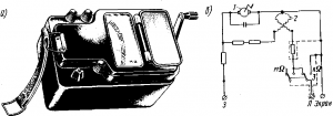
Figure 1. Probe circuits for measuring large (a) and small (b) resistances

Figure 2. Circuits for measuring large (a) and small (b) resistances ammeter-voltmeter method In the basic circuits of the indirect method, voltage and current meters are used.
 Figure 1, a shows a circuit suitable for measuring resistances of the same order as the input resistance Rv of the voltmeter Rн. Having measured the voltage U0 with short-circuited Rx, the resistance Rx is determined by the formula Rx = Rу(U0/Ux-1).
When measured according to the diagram in Fig. 5.1, b resistors of high resistance are connected in series with the meter, and small resistors are connected in parallel.
For the first case, Rx = (Ri + Rd)(Ii/Ix-1), where Ii is the current through the meter with Rx short-circuited; for the second case
![]()
where Ii is the current through the meter in the absence of Rx, Rd is an additional resistor.
The ammeter-voltmeter method is more universal, allowing one to measure resistance under certain operating modes, which is important when measuring nonlinear resistance (see Fig. 2).
For the diagram in Fig. 2, a
![]()
For the diagram in Fig. 2, b
Relative methodological measurement error:
Ra and Rv are the resistances of the ammeter and voltmeter.

Rice. 3. Circuits of ohmmeters with serial (a) and parallel (b) measurement circuits
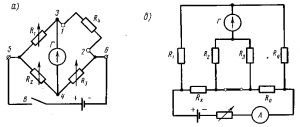
Rice. 4. Bridge circuits for measuring resistance: a - single bridge, b - double.
From the expressions for the relative error it is clear that the diagram in Fig. 2, a provides less error when measuring large resistances, and the circuit in Fig. 2, b - when measuring small ones.
The measurement error using the ammeter-voltmeter method is calculated using the formula
![]()
where gв, ga are the accuracy classes of the voltmeter and ammeter; Up, Ip - measurement limits of the voltmeter and ammeter.
Direct measurement of DC resistance is carried out with ohmmeters. If resistance values are more than 1 Ohm, ohmmeters with a series measurement circuit are used, and for measuring low resistances - with a parallel circuit. When using an ohmmeter in order to compensate for changes in supply voltage, it is necessary to set the arrow of the device. For a series circuit, the arrow is set to zero when the measured resistance is shunted. (Bypassing is usually performed using a button specially provided in the device). For a parallel circuit, before starting the measurement, set the arrow to the “∞” mark.
To cover the range of small and large resistances, they build ohmmeters in parallel-series circuit. In this case, there are two Rx reading scales.
The highest accuracy can be achieved using the bridge measurement method. Medium resistances (10 Ohm - 1 MOhm) are measured using a single bridge, and small ones - using a double bridge.
The measured resistance Rx is included in one of the arms of the bridge, the diagonals of which are connected respectively to the power source and the null indicator; as the latter, a galvanometer, a microammeter with a zero in the middle of the scale, etc. can be used.
Figure 5. Circuits for measuring large (a) and small (b) alternating current resistances
The equilibrium condition of both bridges is determined by the expression
Shoulders R1 and R3 are usually made in the form resistance stores (shop bridge). Using R3, a range of R3/R2 ratios are set, usually multiples of 10, and using R1, the bridge is balanced. The measured resistance is counted according to the value set by the handles of the resistance magazines. The bridge can also be balanced by smoothly changing the ratio of resistors R3/R2, made in the form of a flux chord, at a certain value of R1 (linear bridge).
 For repeated measurements of the degree of compliance of resistances with a certain specified value Rн, unbalanced bridges. They are balanced at Rx=Rн. Using the indicator scale, you can determine the deviation of Rx from Rн as a percentage.
They work on the principle of self-balancing automatic bridges. The voltage that occurs when there is an imbalance at the ends of the diagonal of the bridge, after being amplified, acts on the electric motor that mixes the slider slider. When balancing the bridge, the engine stops, and the position of the slider determines measured resistance value.
Electrical resistances are conventionally divided into small (no more than 1 Ohm), medium (from 1 to 10 5 Ohms), and, accordingly, large (over 10 5 Ohms). They can also be measured in various ways. When measuring small ones, the voltmeter-ammeter method, as well as the bridge method, is used. For averages, the methods of voltmeter-ammeter, bridge (single bridges), compensation and direct assessment methods (ohmmeters) are applicable. To measure large resistances, they are used, which implement the method of direct assessment.
Because in this case I A ≈I R relative to R and the equality I V «I R will be satisfied. With an average R value, the following scheme is recommended:

Since in this case U V ≈U R due to Accordingly applying Ohm’s law we get:
Due to the presence of internal resistances in the devices, an error occurs, which is the main disadvantage of this method. But when measuring small R, the resistance of the voltmeter will be equal to R V >100R, and for measuring medium R of the ammeter R A<100R, то в таком случае суммарная погрешность не будет более 1%.
Direct assessment method
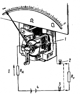
To implement this method, you need to use an ohmmeter, the diagram of which is below:

This device consists of an MI measuring mechanism (magnetoelectric type of mechanism), the scale of which is graduated in ohms. There is also a direct current power source U and an additional resistor R d. The measured resistance R X is connected to the output terminals A and B. Accordingly, the current will flow in the circuit:
![]()
Where R D, R I, R X are the additional resistor and resistance of the measuring mechanism and, accordingly, the object that is to be measured. In this case, the angle of deflection of the instrument arrow will be equal to:
![]()
Where S 1 is the sensitivity of the current meter.
If clamps A and B are opened (), then the angle of deflection of the instrument needle will be equal to zero α=0, and if they are short-circuited (R=0), then the angle of deflection will be maximum. Therefore, the ohmmeter has a reverse scale - zero is on the right.
Ohmmeters are quite convenient for practical use, but they have a fairly high error (accuracy class 2.5). This is due to the instability of the power source and the unevenness of the scale. In order to eliminate the cause of scale unevenness in ohmmeters, ratiometric measuring mechanisms began to be used:

Such devices are called megohmmeters. To obtain a power source, megohmmeters use small generators with voltages up to 2500 Volts and driven manually. In electronic megohmmeters, batteries or an external power source connected through a special power supply unit for the device can be used as a source. Meggers are used to measure high resistances, such as the insulation resistance of conductors. For measurements above 10 9 Ohms, special electronic devices are used, which are called teraohmmeters.
Bridge method
Devices used to implement such measurements are called measuring bridges. A four-arm or single bridge contains two diagonals and four arms:

The bridge is formed by three resistors, the values of which are known - R 2, R 3, R 4 and, accordingly, a resistance, the value of which must be measured R x. It is necessary to connect a power source to one of the diagonals of the bridge, for this case the E 0 source is connected to terminals a and b, and the other is a zero indicator NI (terminals c and d), which serves as an indicator of the symmetry of the bridge. When the potentials at points c and d are equal, then the deviation in the NI flows current I NI = 0 and its deviation is also zero. The bridge is in a state of balance. The following relationships will be satisfied: I 1 = I 2, I 3 = I 4, R x I 1 = R 3 I 3, R 2 I 2 = R 4 I 4. Taking into account the equality of currents and dividing the last two equations term by term, we obtain:
![]()
From this expression we can isolate the required resistance:
The R2 arm is called the comparison arm, and the relationship arms R3 and R4, respectively.
The single bridge method measures only average resistances. It is not recommended to measure small and large resistances with them. The lower measurement limit of the bridge (units of Ohm) is limited by the influence of the resistance of the wires and contacts that are connected to the AC arm in series with the measurement object R x. The upper limit (10 5 Ohms) is limited by the shunting effect of leakage currents.
Compensation method
It is used to obtain increased measurement accuracy. Below is a diagram of such an installation:
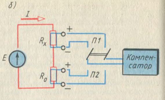
This circuit includes a DC compensator, a two-position switch (P2 and P1), a model resistor R0, as well as a power source E and a measured resistor Rx. By measuring the voltage drop across each resistor at two different switch positions, they determine - U R 0 = R 0 I and U R X = R X I. From these expressions the following formula can be obtained:
When performing measurements, it is necessary to maintain current I constant and not allow its value to change to ensure measurement accuracy.
Measurement using ammeter and voltmeter method. The resistance of any electrical installation or section of an electrical circuit can be determined using an ammeter and voltmeter using Ohm's law. When switching on the devices according to the diagram in Fig. 339, and not only the measured current I x passes through the ammeter, but also the current I v flows through the voltmeter. Therefore the resistance
R x = U / (I – U/R v) (110)
Where Rv - voltmeter resistance.
When switching on the devices according to the diagram in Fig. 339, b the voltmeter will measure not only the voltage drop Ux at a certain resistance, but also the voltage drop in the ammeter winding U A = IR A. Therefore
R x = U/I – R A (111)
Where R A - ammeter resistance.
In cases where the resistance of devices is unknown and, therefore, cannot be taken into account, it is necessary to use the circuit in Fig. 1 when measuring small resistances. 339a, and when measuring high resistances - with the circuit in Fig. 339, b. In this case, the measurement error, determined in the first circuit by the current I v, and in the second by the voltage drop UA, will be small compared to the current I x and voltage U x.
Resistance measurement with electric bridges. The bridge circuit (Fig. 340, a) consists of a power source, a sensitive device (galvanometer G) and four resistors included in the arms of the bridge: with an unknown resistance R x (R4) and known resistances R1, R2, R3, which can be used during measurements change. The device is connected to one of the bridge diagonals (measuring), and the power source is connected to the other (supply).
Resistances R1 R2 and R3 can be selected such that when contact B is closed, the readings of the device will be zero (in
In some cases it is customary to say that the bridge is balanced). At the same time, unknown resistance
R x = (R 1 /R 2)R 3 (112)
In some bridges, the ratio of the arms R1/R2 is set constant, and the balance of the bridge is achieved only by selecting the resistance R3. In others, on the contrary, the resistance R3 is constant, and equilibrium is achieved by selecting the resistances R1 and R2.
Resistance measurement with a DC bridge is carried out as follows. An unknown resistance R x (for example, the winding of an electrical machine or apparatus) is connected to terminals 1 and 2, a galvanometer is connected to terminals 3 and 4, and a power source (dry galvanic cell or battery) is connected to terminals 5 and 6. Then, by changing the resistances R1, R2 and R3 (which are used as resistance stores switched by the corresponding contacts), they achieve bridge equilibrium, which is determined by the zero reading of the galvanometer (with contact B closed).
There are various designs of DC bridges, the use of which does not require calculations, since the unknown resistance R x is measured on the instrument scale. The resistance stores mounted in them allow you to measure resistances from 10 to 100,000 Ohms.
When measuring small resistances with conventional bridges, the resistances of connecting wires and contact connections introduce large errors into the measurement results. To eliminate them, double DC bridges are used (Fig. 340, b). In these bridges, the wires connecting a resistor with a measured resistance R x and some standard resistor with a resistance R0 with other resistors of the bridge, and their contact connections are connected in series with the resistors of the corresponding arms, the resistance of which is set to at least 10 Ohms. Therefore, they have virtually no effect on the measurement results. The wires connecting resistors with resistances R x and R0 are included in the power circuit and do not affect the equilibrium conditions of the bridge. Therefore, the accuracy of measuring small resistances is quite high. The bridge is designed so that when adjusting it, the following conditions are met: R1 = R2 and R3 = R4. In this case
R x = R 0 R 1 / R 4 (113)
Double bridges allow you to measure resistances from 10 to 0.000001 ohms.
If the bridge is not balanced, then the needle in the galvanometer will deviate from the zero position, since the current of the measuring diagonal at constant values of resistances R1, R2, R3, etc. d.s. the current source will depend only on the change in resistance R x. This allows you to calibrate the galvanometer scale in units of resistance R x or any other units (temperature, pressure, etc.) on which this resistance depends. Therefore, an unbalanced DC bridge is widely used in various devices for measuring non-electrical quantities by electrical methods.
Various AC bridges are also used, which make it possible to measure inductance and capacitance with great accuracy.
Measuring with an ohmmeter. The ohmmeter is a milliammeter 1 with a magnetoelectric measuring mechanism and is connected in series with the measured resistance R x (Fig. 341) and an additional resistor R D in the DC circuit. At constant e. d.s. source and resistance of the resistor R D the current in the circuit depends only on the resistance R x. This allows you to calibrate the instrument scale directly in ohms. If the output terminals of the device 2 and 3 are short-circuited (see the dashed line), then the current I in the circuit is maximum and the arrow of the device deviates to the right at the greatest angle; on the scale this corresponds to a resistance of zero. If the device circuit is open, then I = 0 and the arrow is at the beginning of the scale; this position corresponds to a resistance equal to infinity.
The device is powered by a dry galvanic cell 4, which is installed in the device body. The device will give correct readings only if the current source has a constant e. d.s. (the same as when calibrating the instrument scale). Some ohmmeters have two or more measurement ranges, such as 0 to 100 ohms and 0 to 10,000 ohms. Depending on this, a resistor with measured resistance R x is connected to different terminals.
Measuring high resistances with megaohmmeters. To measure insulation resistance, megohmmeters of the magnetoelectric system are most often used. They use logometer 2 as a measuring mechanism (Fig. 342), the readings of which
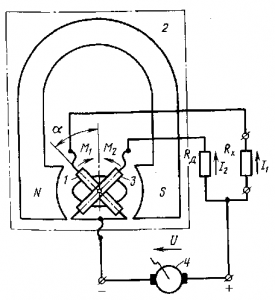
They do not depend on the voltage of the current source supplying the measuring circuits. Coils 1 and 3 of the device are located in the magnetic field of a permanent magnet and are connected to a common power source 4.
An additional resistor R d is connected in series with one coil, and a resistor with resistance R x is connected in the circuit of the other coil.
A small DC generator 4 called an inductor is usually used as a current source; The generator armature is rotated by a handle connected to it through a gearbox. Inductors have significant voltages from 250 to 2500 V, thanks to which large resistances can be measured with a megohmmeter.
When the currents I1 and I2 flow through the coils interact with the magnetic field of a permanent magnet, two oppositely directed moments M1 and M2 are created, under the influence of which the moving part of the device and the pointer will occupy a certain position. As was shown in § 100, the position of the movable
part of the ratiometer depends on the ratio I1/I2. Therefore, when R x changes, will the angle change? arrow deviations. The megohmmeter scale is calibrated directly in kilo-ohms or mega-ohms (Fig. 343, a).
To measure the insulation resistance between the wires, you need to disconnect them from the current source (from the network) and connect one wire to terminal L (line) (Fig. 343,b), and the other to terminal 3 (ground). Then, by rotating the handle of the inductor 1 megohmmeter, the insulation resistance is determined on the scale of the ratiometer 2. Switch 3 in the device allows you to change the measurement limits. The voltage of the inductor, and therefore the speed of rotation of its handle, theoretically does not affect the measurement results, but in practice it is recommended to rotate it more or less evenly.
When measuring the insulation resistance between the windings of an electric machine, disconnect them from each other and connect one of them to terminal L and the other to terminal 3, after which, by rotating the inductor handle, the insulation resistance is determined. When measuring the insulation resistance of the winding relative to the housing, it is connected to terminal 3, and the winding to terminal L.
RESISTANCE MEASUREMENT METHODS
Electrical resistance is the main electrical characteristic of a conductor, a value characterizing the resistance of an electrical circuit or its section to electric current. Resistance can also be called a part (more often called a resistor) that provides electrical resistance to current. Electrical resistance is caused by the conversion of electrical energy into other forms of energy and is measured in Ohms.
Resistance (often denoted by the letter R) is considered, within certain limits, to be a constant value for a given conductor and can be defined as
Where
R - resistance;
U is the electrical potential difference at the ends of the conductor, measured in volts;
I is the current flowing between the ends of the conductor under the influence of a potential difference, measured in amperes.
For practical measurement of resistance, many different methods are used, depending on the measurement conditions and the nature of the objects, the required accuracy and speed of measurements. For example, there are methods for measuring resistance at direct current and at alternating current, measuring high resistances, small and ultra-small resistances, direct and indirect, etc.
The purpose of the work is to identify the main, most common in practice, methods for measuring resistance.
DC Resistance Measurement
The main methods for measuring DC resistance are the indirect method, the direct estimation method, and the bridge method. The choice of measurement method depends on the expected value of the measured resistance and the required measurement accuracy. Of the indirect methods, the most universal is the ammeter-voltmeter method.
Ammeter-voltmeter method
This method is based on measuring the current flowing through the measured resistance and the voltage drop across it. Two measurement schemes are used: measurement of large resistances (a) and measurement of small resistances (b). Based on the results of measuring current and voltage, the desired resistance is determined.
For circuit (a), the desired resistance and relative methodological error can be determined using the formulas:
Where Rx is the resistance being measured, and Ra is the resistance of the ammeter.
For circuit (b), the desired resistance and the relative methodological error of measurement are determined by the formulas:
It is clear from the formula that when calculating the desired resistance using an approximate formula, an error arises because when measuring currents and voltages in the second circuit, the ammeter also takes into account the current that passes through the voltmeter, and in the first circuit, the voltmeter measures the voltage in addition to the resistor also on the ammeter .
From the definition of relative methodological errors it follows that measurement according to scheme (a) provides a smaller error when measuring large resistances, and measurement according to scheme (b) - when measuring small resistances. The measurement error using this method is calculated using the expression:
“The instruments used for measurement must have an accuracy class of no more than 0.2. The voltmeter is connected directly to the resistance being measured. The current during measurement should be such that the readings are measured on the second half of the scale. In accordance with this, the shunt used to be able to measure current with a device of class 0.2 is also selected. In order to avoid heating the resistance and, accordingly, reducing the accuracy of measurements, the current in the measurement circuit should not exceed 20% of the nominal one.”
The advantage of the ammeter and voltmeter measurement method circuits is that the same current can be passed through the resistor with the measured resistance as in its operating condition, which is important when measuring resistances whose values depend on the current.
Direct assessment method.
The direct assessment method involves measuring DC resistance using an ohmmeter. An ohmmeter is a direct reading measuring device for determining electrical active (active resistances are also called ohmic resistances) resistances. Usually the measurement is made using direct current, however, some electronic ohmmeters can use alternating current. Types of ohmmeters: megohmmeters, teraohmmeters, gigaohmmeters, milliohmmeters, microohmmeters, differing in the range of measured resistances.
According to the principle of operation, ohmmeters can be divided into magnetoelectric - with a magnetoelectric meter or magnetoelectric logometer (megohmmeters) and electronic, which are analog or digital.
“The operation of a magnetoelectric ohmmeter is based on measuring the current flowing through the measured resistance at a constant voltage of the power source. To measure resistances from hundreds of ohms to several megaohms, the meter and the measured resistance rx are connected in series. In this case, the current strength I in the meter and the deviation of the moving part of the device a are proportional: I = U/(r0 + rx), where U is the voltage of the power source; r0 is the resistance of the meter. For small values of rx (up to several ohms), the meter and rx are switched on in parallel.”
Ratiometric megaohmmeters are based on a ratiometer, to the arms of which exemplary internal resistors and the measured resistance are connected in different combinations (depending on the measurement limit), the reading of the ratiometer depends on the ratio of these resistances. As a source of high voltage necessary for carrying out such measurements, such devices usually use a mechanical inductor - a manually driven electric generator; in some megohmmeters, a semiconductor voltage converter is used instead of an inductor.
The operating principle of electronic ohmmeters is based on converting the measured resistance into a voltage proportional to it using an operational amplifier. The resistor being measured is connected to the feedback circuit (linear scale) or to the input of the amplifier. A digital ohmmeter is a measuring bridge with automatic balancing. Balancing is carried out by a digital control device by selecting precision resistors in the bridge arms, after which the measuring information from the control device is supplied to the display unit.
“When measuring small resistances, an additional error may occur due to the influence of the transition resistance at the connection points. To avoid this, the so-called four-wire connection method is used. The essence of the method is that two pairs of wires are used - one pair supplies a current of a certain strength to the object being measured, and using the other pair, a voltage drop proportional to the current strength and resistance of the object is supplied from the object to the device. The wires are connected to the terminals of the two-terminal network being measured in such a way that each of the current wires does not directly touch the corresponding voltage wire, and it turns out that the transition resistances at the contact points are not included in the measuring circuit.”
Bridges for measuring DC resistance
Single bridges are widely used to measure DC resistance. Single bridges are four-arm bridges powered by a DC source. There are a number of designs of these devices with different characteristics. The bridge error depends on the measurement limits and is usually indicated in the bridge passport.
Structurally, bridges are designed in the form of portable devices; they are designed to work with their own or external zero indicator. When measuring small resistances, the measurement result is significantly influenced by the resistance of the contacts and connecting wires, which are added to the measured resistance. To reduce this influence, special methods are used to connect Rx to the bridge, for which the bridge has four clamps:
When measuring resistances from 10 to 1,000,000 Ohms, terminals 1 and 2, as well as 3 and 4, are shorted with jumpers and a resistor with the measured resistance is connected to terminals 2 and 3. Resistance Rx is measured along with the resistance of the wires and contacts with which it is connected to terminals 2 and 3. When measuring small resistances (those less than 10 ohms), the error introduced by the connecting wires and contacts can be large. You can reduce it by connecting the measured resistor to 4 terminals - 1 and 2, 3 and 4. In this case, the jumpers between points 1 and 2, 3 and 4 are removed, and points A and 4, B and 1 are connected to each other.
In this case, the resistance of the wire from Rx to terminal 2 enters the arm with resistance R, and the resistance of the wire from Rx to terminal 3 enters the arm with resistance R1. Resistances R and R1 are significantly greater than the resistance of the wires.
When measuring very small resistances, the bridge in question has large errors due to low sensitivity. An increase in sensitivity by increasing the supply current is limited by the permissible power dissipated in the bridge arms. Double bridges do not have this disadvantage.
The most common circuit, in which the influence of wires and contacts is minimized, is the double bridge circuit:
The resistances of the bridge arms are designated by R with the corresponding indices, and the resistances of the connecting wires and contacts by R'1, R'2, etc.
If we take the resistance of the connecting wires and contacts as included in the resistance values indicated by letters with the corresponding indices. When the bridge is in equilibrium, the following conditions are met:
Solving these equations for Rx we find:
From this equation it follows that if the condition R1/R2 = R3/R4 is met, then the second term of this equation will be equal to zero and the measured resistance Rx can be determined from the equality:
“Double bridges are made with constant or variable shoulder ratios. The galvanometer at the moment of equilibrium can be shorted to a small resistance, therefore, when choosing a galvanometer, one should prefer devices with a small external critical resistance and the greatest voltage sensitivity possible. In order to expand the measurement limits in industrial devices, double bridges are combined with single bridges, providing wide measurement limits.”
Measuring very high resistances
There are several methods for measuring high resistances. One is the direct deflection method, in which the current flowing through the resistance being measured under the influence of a known voltage is directly determined by a sensitive galvanometer connected in series with the resistance. The voltage across the resistance is determined by the reading of a voltmeter connected in parallel with the resistance. The value of the required resistance is found based on Ohm's law by dividing the voltage by the amount of current flowing through it. The difference between this method and the ammeter-voltmeter method is only in replacing the ammeter with a galvanometer.
This same method underlies commercially produced direct-reading megohmmeters. The measuring mechanism in them, as a rule, is of the magnetoelectric type (due to its accuracy, low self-consumption and uniformity of the scale). For a certain operating voltage, the device is calibrated directly in units of resistance. Due to the limited sensitivity of megaohmmeters, the operating voltage of megaohms is high (up to 2500 V).
It is very common to measure large resistances using potentiometric circuits. In this case, the measurement limits can be significantly greater, and the equipment is more reliable and durable than with the direct deflection method. Most industrial megohmmeters and teraohmmeters use the potentiometric method. The measured Rx and reference resistance Ro form a divider, powered by a stable DC voltage source U. The voltage drop across the reference resistance is measured with a voltmeter V with a high input resistance. At a certain voltage value U, each reading u of the voltmeter corresponds to a very specific value of the measured resistance:
Rx = (U - u)Ro/u,
and the voltmeter is calibrated in units of resistance.
When implementing the potentiometric measurement method, two problems arise: producing a stable reference resistance and choosing a high-resistance and sensitive voltmeter. At large limits, resistance measurements Ro can only be made using non-wire measurements. Potentiometric circuits differ only in the method of measuring the voltage across the reference resistance.
AC Resistance Measurement
Imitance meter
An immittance meter (or RLC meter) is a radio measuring device designed to determine the parameters of the impedance or admittance of an electrical circuit. The RLC in the name “RLC meter” is made up of widely used circuit names of elements whose parameters this device can measure: R - Resistance, C - Capacitance, L - Inductance.
Among the main methods for measuring the parameters of electrical circuits are bridge methods and a method associated with the use of Ohm's law relations on alternating current.
The operating principle of bridge immittance meters is based on the use of a measuring bridge, for balancing which the device contains sets of exemplary active and reactive resistances. Such devices can only operate at fixed frequencies. The implementation of digital instruments for measuring the parameters of electrical circuits based on bridge methods is accompanied by a noticeable complication of their circuitry and automation of balancing processes.
“Devices based on the use of Ohm’s law relations are simpler from the point of view of circuit implementation and automated receipt of measurement results. The measuring principle of such immittance meters is based on the analysis of the passage of a test signal (usually sinusoidal) with a given frequency through a measured circuit having a complex resistance. The operating frequency voltage from the internal generator is supplied to the object being measured. On a selected section of the circuit, voltage, current and phase shift between them are measured. The measured values are used to calculate the circuit parameters.”
Measuring line
This is a device for studying the electric field distribution along a microwave transmission line. The measuring line is a segment of a coaxial line or waveguide with an indicator moving along it, marking the nodes (antinodes) of the electric field. Using the measuring line, the distribution of the electromagnetic field strength is studied, from which the standing wave coefficient is determined as the ratio of the wave amplitudes at the antinode and the node and the phase of the reflection coefficient based on the displacement of the node. Knowing these parameters, you can find the total resistance using the impedance pie chart. Measurements are made using a measuring generator as a signal source. To take readings, as a rule, a galvanometer or voltage ratio meter is used. Measuring lines are used at frequencies from hundreds of megahertz to hundreds of gigahertz.
“The line consists of three main units: a piece of transmission line with a longitudinal narrow slot, a probe head and a carriage with a mechanism for moving the probe head along the line. The probe head is a resonator excited by a probe - a thin wire immersed through a slot into the internal cavity of the waveguide. The depth of immersion of the probe in the line is adjusted with a special screw located on top of the probe head. A semiconductor detector connected to an indicator device is placed inside the resonator. When the probe moves along a line within which there is an electromagnetic field, an electromotive force is induced in the probe, proportional to the field strength in the cross section where the probe is located. This e. d.s. excites the resonator, creating electromagnetic oscillations in it. To reduce the distorting effect of the probe on the electromagnetic field in the line and increase the sensitivity of the line, the cavity resonator of the probe head is adjusted to resonance with the frequency of electromagnetic oscillations.”
A device called an impedance meter is also used to measure the impedance of a circuit. Impedance meters are less sensitive than line meters, but they are significantly smaller, especially at the lower end of the frequency range. The standing wave ratio, as in measuring lines, is determined from the ratio of the low-frequency indicator readings at extreme signal values. The impedance of the object under study is found from a pie chart of impedances based on the values of the standing wave coefficient and the phase of the reflection coefficient.
conclusions
There are many different methods for measuring resistance. They are all different from each other. And in each case it is necessary to choose an individual method for measurement. The most common method of indirectly measuring resistance is the method of measuring through an ammeter and a voltmeter. It is used in a variety of devices for measuring resistance to both direct and alternating current. However, it is not always possible to use ordinary voltmeters and ammeters to measure voltage and current, since they can produce errors, for example, when measuring very low resistances due to the resistance of connecting wires and contacts. Therefore, to correctly measure resistance, it is important to choose a method in which the measurement error is minimal.
METHODS FOR CAPACITANCE AND INDUCTANCE MEASUREMENT
Measuring instruments for direct assessment of the value of the measured capacitance include microfarad meters, the operation of which is based on the dependence of the current or voltage in the alternating current circuit on the value of the measured capacitance included in it. The capacitance value is determined using the dial meter scale.
More widely, balanced AC bridges are used to measure the parameters of capacitors and inductances, which make it possible to obtain a small measurement error (up to 1%). The bridge is powered by generators operating at a fixed frequency of 400-1000 Hz. Rectifier or electronic millivoltmeters, as well as oscilloscope indicators, are used as indicators.
The measurement is made by balancing the bridge as a result of alternate adjustment of its two arms. The readings are taken from the limbs of the handles of those arms with which the bridge is balanced.
As an example, let's consider the measuring bridges that are the basis of the EZ-3 inductance meter (Fig. 1) and the E8-3 capacitance meter (Fig. 2).
Rice. 1. Bridge circuit for measuring inductance
Rice. 2. Bridge circuit for measuring capacitance with small (a) and large (b) losses
When the bridge is balanced (Fig. 1), the inductance of the coil and its quality factor are determined by the formulas Lx = R1R2C2; Qx = wR1C1.
When balancing bridges (Fig. 2), the measured capacitance and loss resistance are determined using the formulas
Measuring capacitance and inductance using the ammeter-voltmeter method
To measure small capacitances (no more than 0.01 - 0.05 μF) and high-frequency inductors in the range of their operating frequencies, resonant methods are widely used. A resonant circuit usually includes a high-frequency generator, inductively or through a capacitance connected to the measuring LC circuit. Sensitive high-frequency devices that respond to current or voltage are used as resonance indicators.
The ammeter-voltmeter method measures relatively large capacitances and inductances when the measuring circuit is powered from a low frequency source of 50 - 1000 Hz. For measurements, you can use the diagrams in Fig. 3.
Figure 3. Circuits for measuring large (a) and small (b) alternating current resistances
According to instrument readings, the total resistance
From these expressions one can determine
When active losses in a capacitor or inductor can be neglected, use the circuit in Fig. 4. In this case
Rice. 4. Schemes for measuring large (a) and small (b) resistances using the ammeter-voltmeter method
Measuring the mutual inductance of two coils
Measuring the mutual inductance of two coils can be done using the ammeter-voltmeter method (Fig. 5) and the method of series-connected coils.
Rice. 5. Measuring mutual inductance using the ammeter-voltmeter method
The value of mutual inductance when measured using the ammeter-voltmeter method
When measuring using the second method, the inductances of two in series are measured
connected coils with consonant LI and counter LII switching on of the coils. Mutual inductance is calculated using the formula
Construction of single DC measuring bridges
A single DC bridge consists of three standard resistors (usually adjustable) R1, R2, R3 (Fig. 1, a), which are connected in series with the measured resistance Rx in the bridge circuit.
One of the diagonals of this circuit is supplied with power from the EMF source GB, and a highly sensitive galvanometer RA is connected to the other diagonal through switch SA1 and limiting resistance Ro.
Rice. 1. Schemes of single DC measuring bridges: a - general; b - with a smooth change in the shoulder ratio and an abrupt change in the comparison shoulder.
The scheme works as follows. When power is applied, currents I1 and I2 pass through resistors Rx, Rl, R2, R3. These currents will cause voltage drops Uab, Ubc, Uad and Udc in the resistors.
If these voltage drops are different, then the potentials of points φa, φb and φc will not be the same. Therefore, if you turn on the galvanometer with switch SA1, then a current equal to Ig = (φb - φd) / Ro will pass through it.
The measuring task is to balance the bridge, that is, to make the potentials of points φb and φd the same, in other words, to reduce the galvanometer current to zero.
To do this, they begin to change the resistances of resistors Rl, R2 and R3 until the galvanometer current becomes zero.
When Ig=0 it can be stated that φb = φd. This is only possible when the voltage drop Uab - Uad and Ubc = Udc.
Substituting the voltage drop values Uad = I2R3, Ubc = I1R1, Udc = I2R2 and Uab = I1Rx into these expressions, we obtain two equalities: I1Rx = I2R3, I1R1 = I2R2
Dividing the first equality by the second, we get Rx / R1 = R3 / R2 or Rx R2 = R1 R3
The last equality is the condition for balancing a single DC bridge.
It follows from it that the bridge will be balanced when the products of the resistances of the opposite arms are the same. From here the measured resistance will be determined by the formula Rx = R1R3 / R2
In real single bridges, either the resistance of resistor R1 is changed (it is called the comparison arm), or the resistance ratio R3/R2.
There are measuring bridges in which only the resistance of the comparison arm changes, and the ratio R3/R2 remains constant. Conversely, only the ratio R3/R2 changes, and the resistance of the comparison arm remains constant.
The most widespread are measuring bridges in which the resistance R1 changes smoothly and the ratio R3/R2 changes in jumps, usually multiples of 10 (Fig. 1, b), for example, in the common P333 measuring bridges.
Each measuring bridge is characterized by a resistance measurement limit from Rmin to Rmax. An important parameter of the bridge is its sensitivity Sm = SgSсх, where Sg=da/dIg is the sensitivity of the galvanometer, Scx=dIg/dR is the sensitivity of the circuit.
Substituting Sg and Scx into Sm, we get Sm = da/ dR.
Sometimes the concept of relative sensitivity of the measuring bridge is used:
Sм= da/ (dR / R).
where dR / R is the relative change in resistance in the measured arm, da is the angle of deflection of the galvanometer needle.
Depending on the design, a distinction is made between magazine and linear (fluid-chord) measuring bridges.
In a store measuring bridge, the shoulder resistances are made in the form of plug or lever multi-valued measures of electrical resistance (resistance stores); in rheochord bridges, the comparison arm is made in the form of a resistance store, and the deflection arms are made in the form of a resistor, divided by a slider into two adjustable parts.
In terms of permissible error, single DC measuring bridges have an accuracy class of: 0.02; 0.05; 0.1; 0.2; 1.0; 5.0. The numerical value of the accuracy class corresponds to the highest permissible relative error value.
The error of a single DC bridge depends on the degree of commensurability of the resistance of the connecting wires and contacts with the measured resistance. The lower the measured resistance, the greater the error. Therefore, double DC bridges are used to measure low resistances.
Construction of double DC bridges
The arms of the double (six-armed) measuring bridge are the measured resistance Rx (made four-clamp to reduce the influence of transition contact resistances and connected to the network through a special four-clamp device), a standard resistor Ro and two pairs of auxiliary resistors Rl, R2, R3, R4.
Rice. 3 DC double measuring bridge circuit
The equilibrium of the bridge is determined by the formula:
Rx = Ro x (R1/R2) - (r R3 / (r +R3 +R4)) x (R1/R2 - R4/R3)
This shows that if two ratios of arms R1/R2 and R4/R3 are equal to each other, then the subtrahend is equal to zero.
Despite the fact that the resistances R1 and R4, when moving the slider D, are set to the same, due to the spread in the parameters of the resistances R2 and R4, this is very difficult to achieve.
To reduce the measurement error, the resistance of the jumper connecting the standard resistor Ro and the measured resistance Rx should be taken as small as possible. Usually a special calibrated resistor r is attached to the device. Then the subtrahend of the expression practically becomes equal to zero.
The value of the measured resistance can be determined by the formula: Rх = Ro R1/R2
Dual DC measuring bridges are designed to operate with variable arm ratios only. The sensitivity of the double bridge depends on the sensitivity of the zero pointer, the parameters of the bridge circuit and the value of the operating current. As the operating current increases, the sensitivity increases.
The most widely used are combined DC measuring bridges, designed to operate using single and double bridge circuits.
2
Systematic, progressive and random errors
Errors that do not change over time or are functions of certain parameters that do not change over time are called systematic. The main distinguishing feature of systematic errors is that they can be predicted and therefore almost completely eliminated by introducing appropriate corrections.
The special danger of constant systematic errors lies in the fact that their presence is extremely difficult to detect. Unlike random, progressive or functions of certain error parameters, constant systematic errors do not manifest themselves externally and can go unnoticed for a long time. The only way to detect them is to verify the device by re-certifying against standard measures or signals,
An example of systematic errors of the second type is the majority of additional errors, which are time-invariant functions of the influencing quantities that cause them (temperatures, frequencies, voltage, etc.). These errors, due to the constancy of the influence functions over time, can also be predicted and corrected by introducing additional corrective converters that perceive the influencing quantity and introduce an appropriate correction to the measurement result.
Progressive (or drift) are unpredictable errors that change slowly over time. These errors, as a rule, are caused by the aging processes of certain parts of the equipment (discharge of power supplies, aging of resistors, capacitors, deformation of mechanical parts, shrinkage of paper tape in recorders, etc.). A feature of progressive errors is that they can be corrected by introducing a correction only at a given point in time, and then they increase unpredictably again. Therefore, unlike systematic errors, which can be corrected by a correction found once for the entire service life of the device, progressive errors require continuous repetition of correction and the more frequent, the smaller their residual value should be. Another feature of progressive errors is that their change over time is a non-stationary random process and therefore, within the framework of a well-developed theory of stationary random processes, they can be described only with reservations.
Random errors are errors that are unpredictable in either sign or size (or have not been sufficiently studied). They are determined by a combination of reasons that are difficult to analyze. The presence of random errors (as opposed to systematic ones) is easily detected during repeated measurements in the form of some scatter in the results obtained. Thus, the main distinguishing feature of random errors is their unpredictability from one reading to another. Therefore, the description of random errors can only be carried out on the basis of probability theory in mathematical statistics.
However, since most of the components of the errors of the means and measurement results are random errors, the only possible developed way to describe them is to use the provisions of the theory of probability and its further development in relation to the processes of information transfer in the form of information theory, and for processing the obtained experimental data, containing random errors - methods of mathematical statistics. Therefore, it is this group of fundamental sections of mathematics that is the basis for the development of the modern theory of error assessments of means, processes and measurement results.
Examples of systematic additive errors are errors from foreign weight on the scale pan, from inaccurate setting of the device to zero before measurement, from thermo-EMF in DC circuits, etc. To eliminate such errors, many measuring instruments provide a mechanical or electrical device for setting zero (zero corrector).
Examples of random additive errors are the error from the induction of a variable EMF at the input of the device, errors from thermal noise, from friction in the supports of the moving part of the measuring mechanism, from unreliable contact when measuring resistance, error from the influence of the planing threshold of devices with manual or automatic balancing, etc. .
The causes of multiplicative errors can be:
changing the amplifier gain;
measuring the stiffness of the pressure gauge sensor membrane or device spring;
changing the reference voltage in a digital voltmeter, etc.
3
The accuracy class of a device is a generalized characteristic of the device, determined by the limits of permissible (main and additional) errors, as well as other characteristics that influence the accuracy.
4
Signals coming from message sources (microphone, television camera, telemetry sensor and others), as a rule, cannot be directly transmitted over a radio frequency channel or optical frequency range. To carry out effective signal transmission in any medium (the atmosphere or glass fiber), it is necessary to transfer the spectrum of signals from the low-frequency region to the region of sufficiently high frequencies.
The procedure for transferring the spectrum from low frequencies to high frequencies is called modulation.
5
Kр=l/T T=Kр∙l, where T is the oscillation period
Кр – scan factor
l - length
T 8.55cm5(μs/cm) = 42.75 (μs)
f=1/T, oscillation frequency
Т=42.75(μs)=42.75〖10〗^(-6)(s)
f = 1/(42.75∙〖10〗^(-6))= 23391.8 (Hz) = 23.39 (kHz)
Brief THEORY
Ohm's law for a homogeneous section of a chain.
If there is a potential difference at the ends of a homogeneous section of the circuit Dj=j 2 -j 1 , then an electric current arises in this circuit. Current strength I flowing through a given section is proportional to the potential difference DJ at the ends of the section and is inversely proportional to the resistance R this section of the circuit (or this conductor)
Magnitude U = I×R called voltage drop across the conductor and is numerically equal to the amount of heat released in a conductor when a unit electric charge passes through it.
For a homogeneous section (i.e., not containing an emf), the potential difference at the ends of the section is numerically equal to the voltage drop in this section, i.e. . Dj= U.
If an ordinary analog voltmeter (the deflection of the needle is determined by the current passing in the frame or coil) is connected to the points 1 And 2 section of the circuit, then it will show the potential difference Dj between these points. The potential difference in this case will be equal to the voltage drop U on a voltmeter, i.e.
U = I V R V (2)
Where R V- voltmeter resistance,
I V- current flowing through the voltmeter.
Conductor resistance.
If a section of the circuit is a conductor of length l constant cross section S, homogeneous chemical composition, then the resistance R this conductor is determined by the formula:
Where r- specific resistance of the material.
Specific resistance is numerically equal to the resistance of a homogeneous conductor of unit length and unit cross-section. It depends on the chemical composition of the conductor material, its temperature, and is measured in the SI system in Ohm×m. In practice, a non-systemic unit is often used - Ohm×mm 2 /m.
At room temperature, conductors made of chemically pure metals have the lowest resistivity. The resistivity of alloys is high, which allows them to be used for the manufacture of resistors with high resistance (rheostats, heating elements, shunts and additional resistances). In table 1 shows the resistivity values of some materials.
Table 1
Methods for measuring resistance.
The main methods for measuring DC resistance are: indirect method, direct estimation method and bridge method. The choice of measurement method depends on the expected value of the resistance being measured and the required accuracy. The most universal of the indirect methods is the “ammeter-voltmeter” method, which consists of the practical use of Ohm’s law for a homogeneous section of the circuit. Indeed, from formulas (1) and (2) it follows
those. measuring potential difference U at the ends of the conductor and current value I, leaking through him, you can determine the resistance R conductor.
Another method for measuring resistance is the bridge method, which is covered in another lab. Bridge circuits do not need to measure currents and voltages, so they provide more accurate results.
The direct assessment method involves measuring DC resistance using an ohmmeter. But measurements with an ohmmeter give significant inaccuracies. For this reason, this method is used for approximate preliminary resistance measurements and for testing switching circuits.
This lab examines the ammeter-voltmeter method.

