Star News


PWM controller for permanent motors. Digital PWM commutator motor speed controller
Any modern power tool or household appliance uses a commutator motor. This is due to their versatility, i.e., the ability to work on both AC and DC voltages. Another advantage is the effective starting torque.
However, the high speed of the collector motor does not suit all users. For smooth start-up and the ability to change the speed, a regulator was invented, which is quite possible to make with your own hands.
Each electric motor consists of a commutator, stator, rotor and brushes. The principle of its operation is quite simple:
In addition to the standard device, there are also:

Regulator device
There are many schemes of such devices in the world. Nevertheless, all of them can be divided into 2 groups: standard and modified products.
Standard device
Typical products are easy to manufacture idinistor, good reliability when changing engine speed. As a rule, such models are based on thyristor regulators. The principle of operation of such schemes is quite simple:
Thus, the speed of the collector motor is adjusted. In most cases, a similar scheme is used in foreign household vacuum cleaners. However, you should be aware that such a speed controller does not have feedback. Therefore, when the load changes, you will have to adjust the speed of the electric motor.
Changed Schemas
 Of course, the standard device suits many lovers of speed controllers to “dig into” electronics. However, without progress and improvement of products, we would still live in the Stone Age. Therefore, more interesting schemes are constantly being invented, which many manufacturers are happy to use.
The most commonly used are rheostatic and integral regulators. As the name implies, the first option is based on a rheostat circuit. In the second case, an integral timer is used.
Rheostats are efficient in changing the number of revolutions of the collector motor. High efficiency is due to power transistors, which take part of the voltage. Thus, the current flow is reduced and the motor runs with less zeal.
Video: speed controller device with power maintenance
The main disadvantage of such a scheme is the large amount of heat generated. Therefore, for trouble-free operation, the regulator must be constantly cooled. Moreover, the cooling of the device should be intensive.
 A different approach is implemented in the integral regulator, where the integral timer is responsible for the load. As a rule, transistors of almost any name are used in such circuits. This is due to the fact that the composition contains a microcircuit that has large values of the output current.
If the load is less than 0.1 amperes, then all the voltage goes directly to the microcircuit, bypassing the transistors. However, for the regulator to work effectively, it is necessary that the gate voltage be 12V. Therefore, the electrical circuit and the voltage of the power supply itself must correspond to this range.
Overview of typical circuits
 It is possible to regulate the rotation of the shaft of a low-power electric motor by connecting a power resistor in series with the absence. However, this option has a very low efficiency and the inability to smoothly change the speed. To avoid such a nuisance, you should consider several regulator schemes that are used most often.
As you know, PWM has a constant amplitude of pulses. In addition, the amplitude is identical to the supply voltage. Therefore, the electric motor will not stop even when running at low speeds.
The second option is similar to the first. The only difference is that it uses operational amplifier. This component has a frequency of 500 Hz and is engaged in the development of pulses that have a triangular shape. Adjustment is also carried out by a variable resistor.
How to DIY
 If you do not want to spend money on purchasing a finished device, you can make it yourself. Thus, you can not only save money, but also get a useful experience. So, for the manufacture of a thyristor regulator, you will need:
- soldering iron (to check the performance);
- wires;
- thyristor, capacitors and resistors;
- scheme.
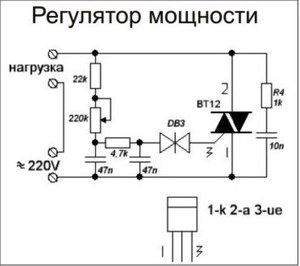
As can be seen from the diagram, only 1 half-cycle is controlled by the regulator. However, for testing performance on a conventional soldering iron, this will be quite enough.
If knowledge on decoding the scheme is not enough, you can familiarize yourself with the text version:

The use of regulators allows more economical use of electric motors. In certain situations, such a device can be made independently. However, for more serious purposes (for example, control of heating equipment), it is better to purchase a ready-made model. Fortunately, there is a wide selection of such products on the market, and the price is quite affordable.
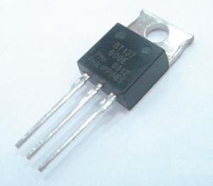
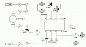
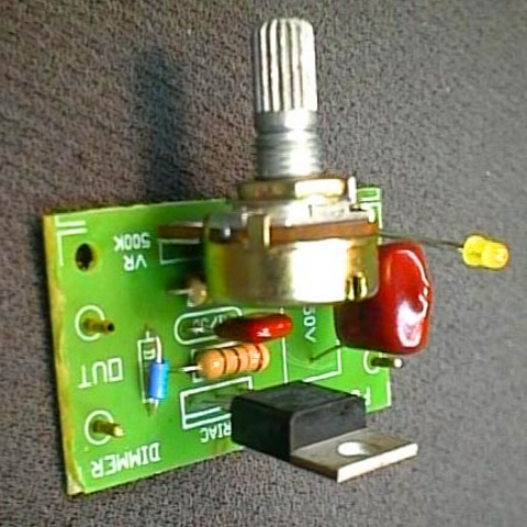
Based on a powerful triac BT138-600, you can assemble an engine speed controller circuit alternating current. This circuit is designed to control the speed of rotation of the electric motors of drilling machines, fans, vacuum cleaners, angle grinders, etc. The motor speed can be adjusted by changing the resistance of the potentiometer P1. Parameter P1 determines the phase of the trigger pulse that opens the triac. The circuit also performs a stabilization function that maintains the speed of the motor even when it is heavily loaded.
For example, when the motor of a drilling machine slows down due to increased metal resistance, the EMF of the motor also decreases. This leads to an increase in voltage in R2-P1 and C3 causing the triac to open longer and the speed increases accordingly.
Regulator for DC motor
The simplest and most popular method for adjusting the speed of rotation of a DC motor is based on the use of pulse width modulation ( PWM
or PWM
). In this case, the supply voltage is applied to the motor in the form of pulses. The pulse repetition rate remains constant, and their duration can change - this is how the speed (power) changes. 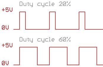
To generate a PWM signal, you can take a circuit based on the NE555 chip. The most simple circuit DC motor speed controller is shown in the figure:

Here VT1 is an n-type field effect transistor capable of withstanding the maximum motor current at a given voltage and load on the shaft. VCC1 is 5 to 16V, VCC2 is greater than or equal to VCC1. The frequency of the PWM signal can be calculated using the formula:
F = 1.44/(R1*C1), [Hz]Where R1 is in ohms, C1 is in farads.
With the ratings indicated in the diagram above, the PWM signal frequency will be equal to:
F = 1.44/(50000*0.0000001) = 290 Hz.
It is worth noting that even modern devices, including high-power control, are based on just such schemes. Naturally, using more powerful elements that can withstand high currents.
When using an electric motor in tools, one of the major problems is adjusting the speed of their rotation. If the speed is not fast enough, then the action of the tool is not effective enough.
If it is excessively high, then this leads not only to a significant waste of electrical energy, but also to a possible burnout of the tool. If the rotation speed is too high, the tool may also become less predictable. How to fix it? For this purpose, it is customary to use a special speed controller.
An engine for power tools and household appliances usually falls into one of 2 main types:
- collector motors.
- asynchronous motors.
In the past, the second of these categories was the most common. Now, approximately 85% of the motors that are used in electric tools, household or kitchen appliances are of the commutator type. This is explained by the fact that they have a greater degree of compactness, they are more powerful and the process of controlling them is simpler.
The operation of any electric motor is built on a very simple principle: if a rectangular frame is placed between the poles of the magnet, which can rotate around its axis, and let along it D.C., the frame will rotate. The direction of rotation is determined according to the “right hand rule”.
This pattern can be used to operate a collector engine.
The important point here is to connect the current to this frame. Since it rotates, special sliding contacts are used for this. After the frame rotates 180 degrees, the current through these contacts will flow in the opposite direction. Thus, the direction of rotation will remain the same. In this case, smooth rotation will not work. To achieve this effect, it is customary to use several dozen frames.
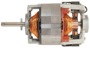
Device
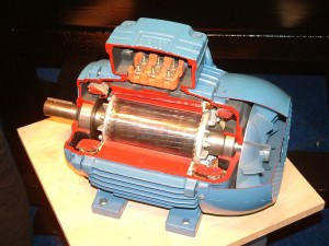
The collector motor usually consists of a rotor (armature), a stator, brushes and a tachogenerator:
- Rotor is the rotating part, the stator is the external magnet.
- Graphite brushes- this is the main part of the sliding contacts, through which voltage is applied to the rotating armature.
- Tachogenerator is a device that monitors the characteristics of rotation. In the event of a violation of the uniformity of movement, it corrects the voltage supplied to the engine, thereby making it smoother.
- stator may contain more than one magnet, but, for example, 2 (2 pairs of poles). Also, instead of static magnets, coils of electromagnets can be used here. Such a motor can work both from direct and from alternating current.
The ease of adjusting the speed of the collector motor is determined by the fact that the rotation speed directly depends on the magnitude of the applied voltage.
In addition, an important feature is that the axis of rotation can be directly attached to a rotating tool without the use of intermediate mechanisms.
If we talk about their classification, then we can talk about:
- collector engines direct current.
- collector engines alternating current.
In this case, we are talking about exactly what current the electric motors are powered by.
Classification can also be made according to the principle of motor excitation. In a collector motor device, electrical power is supplied to both the rotor and the stator of the motor (if it uses electromagnets).
The difference is how these connections are organized.
Here it is customary to distinguish:
- parallel excitement.
- Consistent arousal.
- Parallel-serial excitation.
Adjustment
Now let's talk about how you can adjust the speed of collector engines. Due to the fact that the speed of rotation of the motor simply depends on the amount of voltage applied, then any means of adjustment that can perform this function is quite suitable for this.
Here are some examples of such options:
- Laboratory autotransformer(LATR).
- Factory adjustment boards used in household appliances (you can use in particular those used in mixers or vacuum cleaners).
- Buttons used in the design of power tools.
- Household regulators lighting with smooth action.
However, all of the above methods have a very important flaw. Along with the decrease in speed, the power of the motor also decreases. In some cases, it can even be stopped with just a hand. In some cases, this may be acceptable, but for the most part, it is a major hurdle.
A good option is to perform speed control through the use of a tachogenerator. It is usually installed at the factory. In the event of deviations in the motor speed, an already corrected power supply corresponding to the desired speed is transferred to the motor. If the motor rotation control is built into this circuit, then there will be no power loss here.
What does it look like constructively? The most common rheostat adjustment of rotation, and made on the basis of the use of semiconductors.
In the first case, we are talking about a variable resistance with mechanical adjustment. It is connected in series to the collector motor. The disadvantage is additional heat generation and additional waste of battery life. With this method of adjustment, there is a loss of motor rotation power. Is a cheap solution. Not applicable for sufficiently powerful motors for the reasons mentioned.
In the second case, when using semiconductors, the motor is controlled by applying certain impulses. The circuit can change the duration of such pulses, which in turn changes the rotation speed without losing power.
How to make with your own hands?
Exist various options regulation schemes. Let's take a look at one of them in more detail.
Here is the scheme of his work:
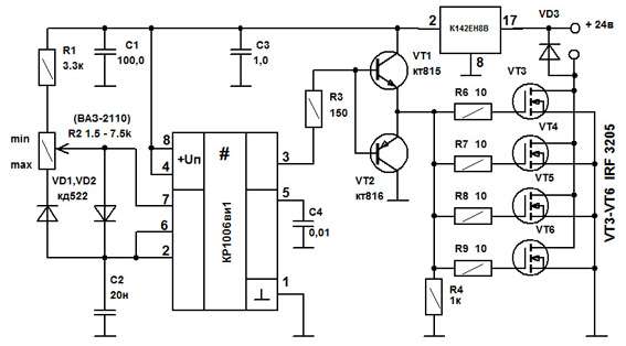
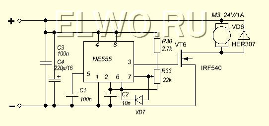
Initially, this device was developed to adjust the commutator motor on electric vehicles. It was about one where the supply voltage is 24 V, but this design is applicable to other motors.
The weak point of the circuit, which was determined during testing of its operation, is poor suitability at very high currents. This is due to some slowdown in the operation of the transistor elements of the circuit.
It is recommended that the current be no more than 70 A. There is no current and temperature protection in this circuit, so it is recommended to build in an ammeter and monitor the current visually. The switching frequency will be 5 kHz, it is determined by the 20 nF capacitor C2.
By changing the current strength, this frequency can change between 3 kHz and 5 kHz. Variable resistor R2 is used to regulate the current. When using the electric motor in a domestic environment, it is recommended to use a standard type regulator.
At the same time, it is recommended to choose the value of R1 in such a way as to correctly adjust the operation of the regulator. From the output of the microcircuit, the control pulse is fed to a push-pull amplifier based on transistors KT815 and KT816, then it goes to transistors.
The printed circuit board has a size of 50 by 50 mm and is made of one-sided fiberglass:

In this diagram, 2 resistors of 45 ohms are additionally indicated. This is done in order to possibly connect a conventional computer fan to cool the device. When using an electric motor as a load, it is necessary to block the circuit with a blocking (snubber) diode, which, according to its characteristics, corresponds to a double value of the load current and a double value of the supply voltage.
Operation of the device in the absence of such a diode can lead to damage due to possible overheating. In this case, the diode will need to be placed on the heat sink. To do this, you can use a metal plate, which has an area of 30 cm2.
Regulating keys work in such a way that the power loss on them is quite small. AT original circuit, a standard computer fan was used. To connect it, a limiting resistance of 100 ohms and a supply voltage of 24 V were used.
The assembled device looks like this:

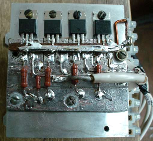
When manufacturing a power unit (in the lower figure), the wires must be connected in such a way that there is a minimum of bends in those conductors through which large currents pass. We see that the manufacture of such a device requires certain professional knowledge and skills. Perhaps in some cases it makes sense to use a purchased device.
Selection criteria and cost
In order to correctly choose the most suitable type of regulator, you need to have a good idea of what varieties of such devices are:
- Various types of control. Can be vector or scalar control system. The former are used more often, while the latter are considered more reliable.
- Regulator power should correspond to the maximum possible power of the motor.
- By voltage it is convenient to choose a device that has the most versatile properties.
- Frequency characteristics. The regulator that suits you should match the highest frequency that the motor uses.
- Other characteristics. Here we are talking about the size warranty period, sizes and other characteristics.
Depending on the purpose and consumer properties, prices for regulators can vary significantly.
For the most part, they are in the range from about 3.5 thousand rubles to 9 thousand:
- Speed controller KA-18 ESC designed for 1:10 scale models. It costs 6890 rubles.
- Speed controller MEGA collector (waterproof). It costs 3605 rubles.
- Speed regulator for LaTrax 1:18 models. Its price is 5690 rubles.
Somehow a friend asked me to look and repair a home-made speed controller for the electric motor of the stove from his “penny”. He praised the regulator as it was possible to smoothly change the engine speed, but something broke in it.
The dimensions of the regulator case immediately alerted me, it was painfully bulky, when I took it apart I saw inside a massive radiator with a couple of KT819 transistors, still in a metal case, and some circuit assembled by soldering leg to leg from which wires went to a variable resistor and to power transistors. Power transistors were broken. Since the engine consumed not a small current, the power transistors, especially at low speeds, got quite hot. Considering such an adjustment scheme outdated, I decided to assemble a PWM (pulse-width modulation) regulator with a powerful field-effect transistor as a key element. As the actual PWM modulator, it was decided to use the well-known 555 timer. It would seem that what can be done on a microcircuit, which was developed more than 30 years ago. Nevertheless, the range of applications of the 555 timer (our analogue KR1006VI1) is practically unlimited. The use of the main operating modes and their modified versions allows the timer to be used in a variety of devices. It is known that the following main functional devices can be assembled on microcircuits of the 555 and 556 families:
- - monostable generator (single vibrator);
- - generator - multivibrator;
- - time delay generator;
- - pulse-width modulator;
- - pulse detector;
- - frequency divider.
The circuit of the motor speed controller turned out to be simple, with a minimum of external piping:
I didn’t poison the printed circuit board for the speed controller of the electric motor, I just cut the contact areas for the timer with a cutter:


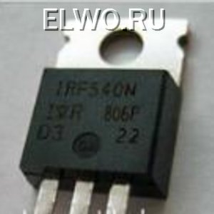
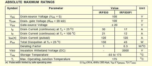
I soldered the timer and assembled the body kit.A powerful n-channel field-effect transistor with an insulated gate, the so-called Power MOSFET IRF540, is used as a key element.
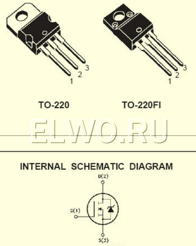
I fixed it on a small radiator - we choose the dimensions based on the operating current of the electric motor. If it is small, then the transistor may not need cooling at all.
Protective diode placed near the engine. The assembled device was placed in the old case, since there was already a mount for it in the car. In the future, it will be possible to place some other device necessary in the car in the same housing. Here is such a "tuning" turned out. With you was - Samodelkin.
On simple mechanisms, it is convenient to install analog current regulators. For example, they can change the speed of rotation of the motor shaft. From the technical side, it is easy to make such a regulator (you will need to install one transistor). Applicable for adjusting the independent speed of motors in robotics and power supplies. The two most common types of regulators are single-channel and dual-channel.
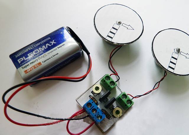
Video #1. Single channel controller in action. Changes the speed of rotation of the motor shaft by turning the knob of the variable resistor.
Video #2. Increasing the speed of rotation of the motor shaft during the operation of a single-channel regulator. The increase in the number of revolutions from the minimum to the maximum value when the variable resistor knob is rotated.
Video number 3. Dual channel controller in action. Independent setting of the speed of rotation of the motor shafts based on tuning resistors.
Video number 4. Regulator output voltage measured digital multimeter. The resulting value is equal to the battery voltage, from which 0.6 volts have been subtracted (the difference occurs due to the voltage drop across the transistor junction). When using a 9.55 volt battery, a change from 0 to 8.9 volts is recorded.
Functions and main characteristics
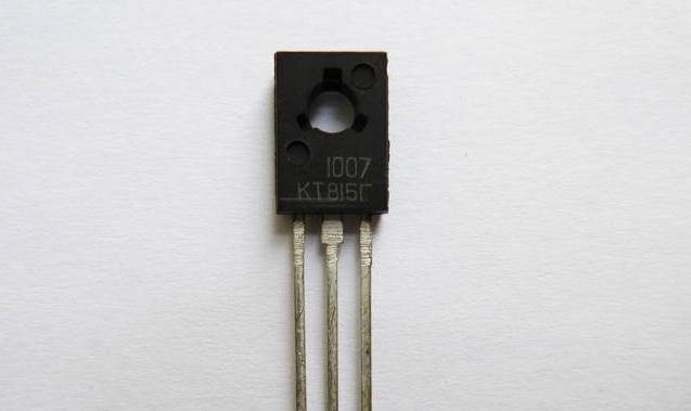
The load current of a single-channel (photo. 1) and two-channel (photo. 2) regulators does not exceed 1.5 A. Therefore, to increase the load capacity, the KT815A transistor is replaced with a KT972A transistor. The pin numbering for these transistors is the same (e-k-b). But the KT972A model is operable with currents up to 4A.
Single channel motor controller
The device controls one motor, powered by a voltage in the range from 2 to 12 volts.
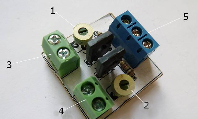
Device design
The main design elements of the regulator are shown in the photo. 3. The device consists of five components: two variable resistance resistors with a resistance of 10 kOhm (No. 1) and 1 kOhm (No. 2), a transistor model KT815A (No. 3), a pair of two-section screw terminal blocks for connecting the motor (No. 4) and battery input (No. 5).
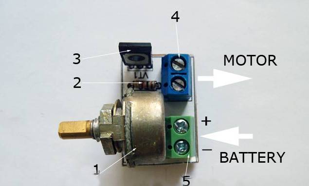
Note 1. Screw terminals are not required. With the help of a thin installation stranded wire, you can connect the motor and power supply directly.
Principle of operation
The operating procedure of the motor controller is described by the wiring diagram (Fig. 1). Taking into account the polarity, the XT1 connector is supplied constant pressure. A light bulb or a motor is connected to the XT2 connector. At the input, a variable resistor R1 is turned on, the rotation of its knob changes the potential at the middle output as opposed to the minus of the battery. Through the current limiter R2, the middle output is connected to the base output of the transistor VT1. In this case, the transistor is connected according to the regular current circuit. The positive potential at the base output is increased by moving up the middle output from the smooth rotation of the variable resistor knob. There is an increase in current, which is due to a decrease in the resistance of the collector-emitter junction in the transistor VT1. The potential will decrease if the situation is reversed.
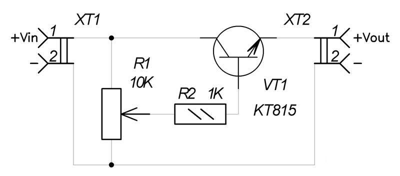
Circuit diagram
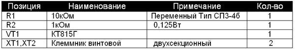
Materials and details
A printed circuit board measuring 20x30 mm is required, made of a sheet of fiberglass laminated on one side (permissible thickness 1-1.5 mm). Table 1 lists the radio components.

Note 2. The variable resistor required for the device can be of any production, it is important to observe the current resistance values \u200b\u200bfor it indicated in table 1.
Note 3. To adjust currents above 1.5A, the KT815G transistor is replaced with a more powerful KT972A (with a maximum current of 4A). In this case, the printed circuit board pattern does not need to be changed, since the pin assignment for both transistors is identical.
Assembly process
For further work, you need to download the archive file located at the end of the article, unzip it and print it. A regulator drawing is printed on glossy paper (file), and an installation drawing (file) is printed on a white office sheet (A4 format).
Next, the drawing of the circuit board (No. 1 in the photo. 4) is glued to the current-carrying tracks on the opposite side of the printed circuit board (No. 2 in the photo. 4). It is necessary to make holes (No. 3 in the photo. 14) on the installation drawing in the seats. The assembly drawing is attached to the printed circuit board with dry glue, while the holes must match. Photo.5 shows the pinout of the KT815 transistor. 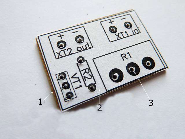
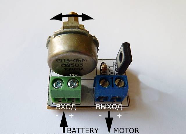
The input and output of the terminal blocks-sockets are marked in white. A voltage source is connected to the terminal block through the clip. A fully assembled single-channel regulator is shown in the photo. The power supply (9 volt battery) is connected at the final stage of assembly. Now you can adjust the speed of rotation of the shaft using the motor, for this you need to smoothly rotate the variable resistor adjustment knob.

To test the device, you need to print a disk drawing from the archive. Next, you need to stick this drawing (No. 1) on thick and thin cardboard paper (No. 2). Then, with the help of scissors, a disk (No. 3) is cut out.
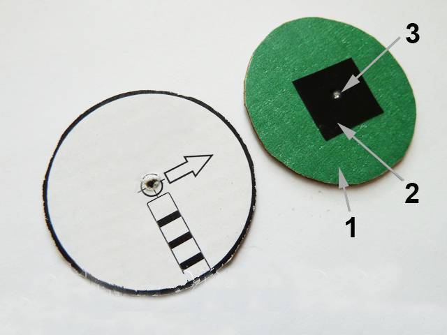
The resulting workpiece is turned over (No. 1) and a square of black electrical tape (No. 2) is attached to the center for better adhesion of the surface of the motor shaft to the disk. You need to make a hole (No. 3) as shown in the image. Then the disk is installed on the motor shaft and you can start testing. The single-channel motor controller is ready!
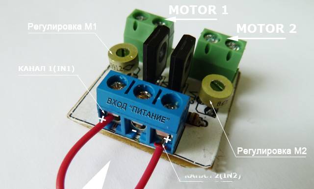
Dual channel motor controller
Used to independently control a pair of motors at the same time. Power is supplied from a voltage in the range from 2 to 12 volts. The load current is rated up to 1.5A per channel.
- Device design
The main components of the design are shown in photo.10 and include: two trimmers for adjusting the 2nd channel (No. 1) and the 1st channel (No. 2), three two-section screw terminal blocks for output to the 2nd motor (No. 3), for the exit to the 1st motor (No. 4) and for the entrance (No. 5).
Note.1 Installation of screw terminals is optional. With the help of a thin installation stranded wire, you can connect the motor and power supply directly.
Principle of operation
The circuit of the two-channel controller is identical to the electrical circuit of the single-channel controller. Consists of two parts (Fig. 2). The main difference: the variable resistance resistor is replaced by a tuning resistor. The speed of rotation of the shafts is set in advance. 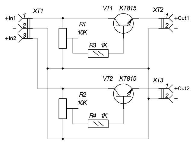
Note.2. To quickly adjust the speed of rotation of the motors, the tuning resistors are replaced with a mounting wire with variable resistance resistors with the resistance values \u200b\u200bspecified in the diagram.
Materials and details
You will need a printed circuit board 30x30 mm in size, made of a sheet of fiberglass laminated on one side with a thickness of 1-1.5 mm. Table 2 lists the radio components.
Assembly process
After downloading the archive file located at the end of the article, you need to unzip it and print it. A drawing of a regulator for thermal transfer (termo2 file) is printed on glossy paper, and an installation drawing (montag2 file) is printed on a white office sheet (A4 format).
The circuit board drawing is glued to the current-carrying tracks on the opposite side of the printed circuit board. Holes are formed on the installation drawing in the seats. The assembly drawing is attached to the printed circuit board with dry glue, while the holes must match. The pinout of the KT815 transistor is being made. To check, temporarily connect inputs 1 and 2 with a mounting wire.

Any of the inputs is connected to the power supply pole (the example shows a 9 volt battery). The minus of the power source is attached to the center of the terminal block. It is important to remember: the black wire is “-”, and the red one is “+”.
The motors must be connected to two terminal blocks, and the desired speed must also be set. After successful tests, you need to remove the temporary connection of the inputs and install the device on the robot model. The two-channel motor controller is ready!
In the presented necessary schemes and drawings for work. The emitters of the transistors are marked with red arrows.