Star News


How to make a power supply from electronic ballast. Power supply: what can be done from an energy-saving lamp
In this article you will find detailed description the manufacturing process of switching power supplies of different power based on the electronic ballast of a compact fluorescent lamp.
You can make a switching power supply for 5 ... 20 watts in less than an hour. It will take several hours to manufacture a 100-watt power supply.
Compact Fluorescent Lamps (CFLs) are now widely used. To reduce the size of the ballast choke, they use a high-frequency voltage converter circuit, which can significantly reduce the size of the choke.
If the electronic ballast fails, it can be easily repaired. But, when the bulb itself fails, the light bulb is usually thrown away.

However, the electronic ballast of such a light bulb is an almost ready-made switching power supply (PSU). The only thing in which the electronic ballast circuit differs from a real switching power supply is the absence of an isolation transformer and a rectifier, if necessary.
At the same time, modern radio amateurs are experiencing great difficulty in finding power transformers to power their homemade products. Even if a transformer is found, its rewinding requires the use of a large amount of copper wire, and the weight and size parameters of products assembled on the basis of power transformers are not encouraging. But in the vast majority of cases, the power transformer can be replaced by a switching power supply. If for these purposes we use ballast from faulty CFLs, then the savings will be a significant amount, especially when it comes to transformers of 100 watts or more.
The difference between the CFL circuit and the pulse power supply
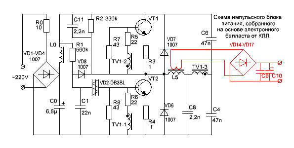
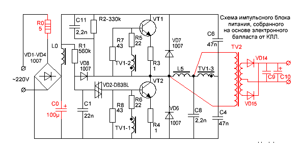
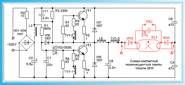
This is one of the most common electrical circuits for energy-saving lamps. To convert the CFL circuit into a switching power supply, it is enough to install only one jumper between points A - A 'and add a pulse transformer with a rectifier. Items that can be deleted are marked in red.
![]()
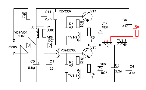
And this is already a complete circuit of a switching power supply, assembled on the basis of a CFL using an additional pulse transformer.
To simplify, the fluorescent lamp and a few parts have been removed and replaced with a jumper.
As you can see, the CFL scheme does not require major changes. Additional elements added to the scheme are marked in red.

What power supply unit can be made from CFL?
The power of the power supply is limited by the overall power of the pulse transformer, the maximum allowable current of key transistors and the size of the cooling radiator, if it is used.
A low power power supply can be built by winding the secondary winding directly onto the frame of an existing inductor.
If the choke window does not allow winding the secondary winding, or if it is required to build a power supply with a power significantly exceeding the power of the CFL, then an additional pulse transformer will be needed.
If you want to get a power supply with a power of more than 100 watts, and a ballast from a 20-30 watt lamp is used, then, most likely, you will have to make small changes to the electronic ballast circuit.
In particular, it may be necessary to install more powerful diodes VD1-VD4 in the input bridge rectifier and rewind the input inductor L0 with a thicker wire. If the current gain of the transistors is insufficient, then the base current of the transistors will have to be increased by decreasing the values of the resistors R5, R6. In addition, you will have to increase the power of the resistors in the base and emitter circuits.
If the generation frequency is not very high, then it may be necessary to increase the capacitance of the isolation capacitors C4, C6.
Pulse transformer for power supply

A feature of self-excited half-bridge switching power supplies is the ability to adapt to the parameters of the transformer used. And the fact that the feedback circuit will not pass through our homemade transformer completely simplifies the task of calculating the transformer and setting up the unit. Power supplies assembled according to these schemes forgive errors in calculations up to 150% and more. Proven in practice.
Don't be scared! You can wind a pulse transformer during watching one movie or even faster if you are going to do this monotonous work with concentration.
Input filter capacitance and voltage ripple
In the input filters of electronic ballasts, due to space savings, small capacitors are used, on which the magnitude of the voltage ripple with a frequency of 100 Hz depends.
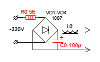
To reduce the level of voltage ripple at the output of the PSU, you need to increase the capacitance of the input filter capacitor. It is desirable that for every watt of PSU power there is one microfarad or so. An increase in capacitance C0 will entail an increase in the peak current flowing through the rectifier diodes at the moment the PSU is turned on. To limit this current, a resistor R0 is needed. But, the power of the original CFL resistor is small for such currents and should be replaced with a more powerful one.
If you want to build a compact power supply, then you can use electrolytic capacitors used in flash lamps of film "malls". For example, Kodak disposable cameras have unmarked miniature capacitors, but their capacity is as much as 100µF at 350 volts.
A power supply with a power close to the power of the original CFL can be assembled without even winding a separate transformer. If the original inductor has enough free space in the magnetic circuit window, then you can wind a couple of dozen turns of wire and get, for example, a power supply for a charger or a small power amplifier.

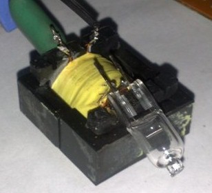
The picture shows that one layer of insulated wire was wound over the existing winding. I used MGTF wire (stranded wire in fluoroplastic insulation). However, in this way it is possible to obtain a power of only a few watts, since most of the window will be occupied by the insulation of the wire, and the cross section of the copper itself will be small.
If more power is required, an ordinary copper lacquered winding wire can be used.
Attention! The original inductor winding is under mains voltage! With the refinement described above, be sure to take care of reliable winding insulation, especially if the secondary winding is wound with ordinary varnished winding wire. Even if the primary winding is covered with a synthetic protective film, an additional paper pad is necessary!

As you can see, the winding of the inductor is covered with a synthetic film, although often the winding of these inductors is not protected at all.

We wind two layers of electric cardboard 0.05 mm thick or one layer 0.1 mm thick over the film. If there is no electric cardboard, we use any paper that is suitable in thickness.
We wind the secondary winding of the future transformer over the insulating gasket. The cross section of the wire should be chosen as large as possible. The number of turns is selected experimentally, since there will be few of them.
In this way, I managed to get power at a load of 20 watts at a transformer temperature of 60ºC, and transistors at 42ºC. To get even more power, at a reasonable temperature of the transformer, was not allowed by the too small area of the window of the magnetic circuit and the resulting cross section of the wire.
The power supplied to the load is 20 watts.
The frequency of self-oscillations without load is 26 kHz.
Self-oscillation frequency at maximum load - 32 kHz
Transformer temperature - 60ºС
Transistor temperature - 42ºС
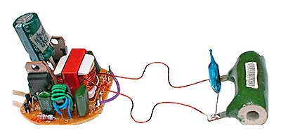
To increase the power of the power supply, I had to wind a TV2 pulse transformer. In addition, I increased the line voltage filter capacitor C0 to 100µF.
Since the efficiency of the power supply is not at all equal to 100%, I had to screw some kind of radiators to the transistors.
After all, if the efficiency of the block is even 90%, you still have to dissipate 10 watts of power.
![]()
I was not lucky, transistors 13003 pos. 1 were installed in my electronic ballast of such a design, which, apparently, is designed to be attached to a radiator using shaped springs. These transistors do not need gaskets, since they are not equipped with a metal pad, but they also give off heat much worse. I replaced them with transistors 13007 pos. 2 with holes so that they can be screwed to the radiators with ordinary screws. In addition, 13007 have several times higher maximum permissible currents.
If you wish, you can safely screw both transistors onto one heatsink. I checked it works.

Only, the cases of both transistors must be insulated from the case of the heatsink, even if the heatsink is inside the case of the electronic device.
Fastening is conveniently carried out with M2.5 screws, on which insulating washers and pieces of an insulating tube (cambric) must first be put on. It is allowed to use heat-conducting paste KPT-8, since it does not conduct current.
Attention! Transistors are under mains voltage, so insulating gaskets must ensure electrical safety conditions!
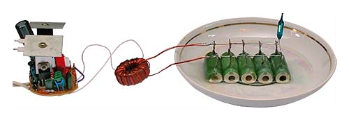
Load dummy resistors are placed in water because their power is insufficient.
The power dissipated at the load is 100 watts.
The frequency of self-oscillations at maximum load is 90 kHz.
The frequency of self-oscillations without load is 28.5 kHz.
The temperature of the transistors is 75ºC.
The heatsink area of each transistor is 27cm².
Throttle temperature TV1 - 45ºC.
TV2 - 2000Nm (Ø28 x Ø16 x 9mm)
Rectifier
All secondary rectifiers of a half-bridge switching power supply must be full-wave. If this condition is not met, then the main line may enter saturation.
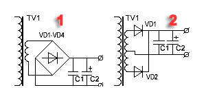
There are two widely used full-wave rectifier circuits.
1. Bridge circuit.
2. Scheme with a zero point.
The bridge circuit saves a meter of wire, but dissipates twice as much energy on the diodes.
The zero point circuit is more economical but requires two perfectly symmetrical secondary windings. Asymmetry in the number of turns or arrangement can lead to saturation of the magnetic circuit.
However, it is the zero-point circuits that are used when it is required to obtain large currents at a low output voltage. Then, for additional minimization of losses, instead of conventional silicon diodes, Schottky diodes are used, on which the voltage drop is two to three times less.
Example.
Rectifiers of computer power supplies are made according to the scheme with a zero point. With a power output of 100 watts and a voltage of 5 volts, even on Schottky diodes, 8 watts can be dissipated.
100 / 5 * 0.4 = 8(Watts)
If you use a bridge rectifier, and even ordinary diodes, then the power dissipated by the diodes can reach 32 watts or even more.
100 / 5 * 0.8 * 2 \u003d 32 (Watts).
Pay attention to this when you design the power supply, so that later you don’t have to look for where half the power has disappeared.

In low-voltage rectifiers, it is better to use a zero-point circuit. Moreover, with manual winding, you can simply wind the winding in two wires. In addition, powerful pulsed diodes are not cheap.
How to properly connect a switching power supply to the network?

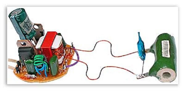
To set up switching power supplies, they usually use just such a switching scheme. Here, the incandescent lamp is used as a ballast with a non-linear characteristic and protects the UPS from failure in abnormal situations. The lamp power is usually chosen close to the power of the tested switching power supply.
When the pulse power supply is idling or at low load, the resistance of the filament of the lamp's kakala is small and it does not affect the operation of the unit. When, for some reason, the current of the key transistors increases, the lamp spiral heats up and its resistance increases, which leads to current limitation to a safe value.

This drawing shows a diagram of a bench for testing and adjusting a pulsed power supply that meets electrical safety standards. The difference between this circuit and the previous one is that it is equipped with an isolation transformer, which provides galvanic isolation of the investigated UPS from the lighting network. The SA2 switch allows you to block the lamp when the power supply delivers more power.
An important operation when testing a PSU is a test on a dummy load. It is convenient to use powerful resistors such as PEV, PPB, PSB, etc. as a load. These "glass-ceramic" resistors are easy to find on the radio market by their green coloring. Red numbers are power dissipation.
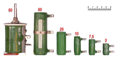
From experience it is known that for some reason the power of the equivalent load is always not enough. The resistors listed above can dissipate two to three times the nominal power for a limited time. When the PSU is turned on for a long time to check the thermal regime, and the power of the equivalent load is insufficient, then the resistors can simply be lowered into the water.
Be careful, beware of the burn!
Load resistors of this type can reach temperatures of several hundred degrees without any external manifestations!
That is, you will not notice any smoke or color change and you can try to touch the resistor with your fingers.
How to set up a switching power supply?
Actually, the power supply, assembled on the basis of a serviceable electronic ballast, does not require special adjustment.
It must be connected to a load dummy and make sure that the PSU is able to deliver the calculated power.
During the run under maximum load, you need to follow the dynamics of the temperature increase of the transistors and the transformer. If the transformer heats up too much, then you need to either increase the cross section of the wire, or increase the overall power of the magnetic circuit, or both.
If the transistors get very hot, then you need to install them on radiators.
If a homemade choke from a CFL is used as a pulse transformer, and its temperature exceeds 60 ... 65ºС, then the load power must be reduced.
What is the purpose of the circuit elements of a switching power supply?
R0 - limits the peak current flowing through the rectifier diodes at the moment of switching on. In CFL, it also often performs the function of a fuse.
VD1 ... VD4 - bridge rectifier.
L0, C0 - power filter.
R1, C1, VD2, VD8 - converter start circuit.
The launch node works as follows. Capacitor C1 is charged from the source through resistor R1. When the voltage on the capacitor C1 reaches the breakdown voltage of the VD2 dinistor, the dinistor unlocks itself and unlocks the VT2 transistor, causing self-oscillations. After the onset of generation, rectangular pulses are applied to the cathode of the VD8 diode and the negative potential securely locks the VD2 dinistor.
R2, C11, C8 - make it easier to start the converter.
R7, R8 - improve the locking of transistors.
R5, R6 - limit the current of the bases of transistors.
R3, R4 - prevent saturation of transistors and act as fuses during breakdown of transistors.
VD7, VD6 - protect transistors from reverse voltage.
TV1 - feedback transformer.
L5 - ballast choke.
C4, C6 - separating capacitors, on which the supply voltage is divided in half.
TV2 - pulse transformer.
VD14, VD15 - pulse diodes.
C9, C10 - filter capacitors.
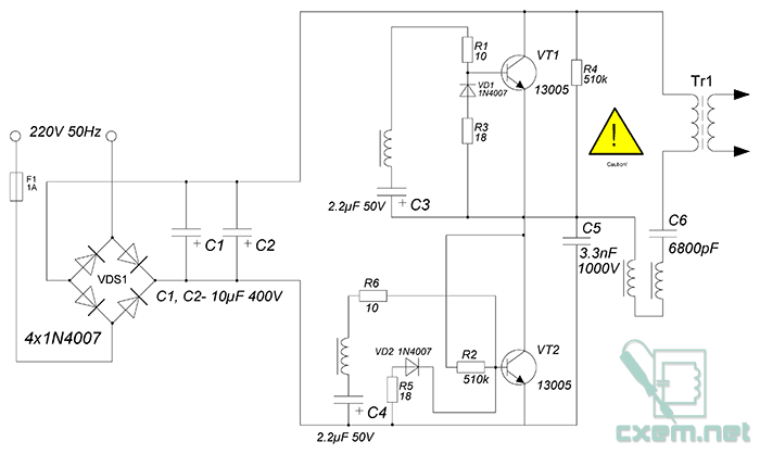
In this article we will consider a simple version of a switching power supply. Ballast from LDS in our time costs a penny, like an electronic transformer (ET) from halogen lamps. We know about the main disadvantages of a UPS for halogens - it works too unstable, the output voltage may deviate in one direction or another, it does not have a surge protector.
But all these shortcomings are nothing compared to the two main ones - with even a second short circuit at the output, the circuit literally explodes. Another main drawback is that the device only works under load, that is, if we connect an LED with a limiting resistor at the output, it will not glow, which makes this UPS very inconvenient for other purposes.
Ballast from LDS - compared to ET units, they are more stable, there are ballasts with line filters. Even in cheap blocks, we can observe a choke, a thermistor and electrolytes for power, a fuse is almost always installed in them. All this makes the ballast durable and reliable.
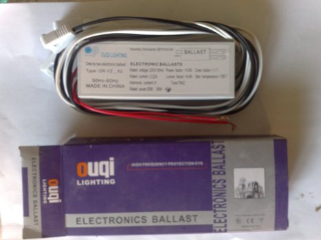
But let's remember that the output voltage of the ballast is only suitable for powering the LDS. In my case, a 40 watt LDS ballast was used.
I decided combine these two schemes to obtain a new type of UPS.
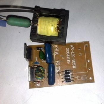
The Chinese electronic transformer for 105 watts was disassembled, a pulse transformer was soldered from the board.
You don't need to do any special modifications, just high voltage from the ballast is fed to the primary winding of the pulse transformer. Power is supplied through a 3kV 6800pF capacitor (both the capacitance and the voltage of the capacitor can deviate in one direction or another by 30-40%)
On the secondary winding transformer we get just 12 volts.

The power of such a power supply is small, but it is enough to create a low-power laboratory UPS. By supplementing the circuit with a rectifier, we get a UPS that can be used as Charger or a power supply for power amplifiers, the scope is quite wide, because no design will work without a power supply.

When supplementing with a diode rectifier, pulse diodes must be used, since the operating frequency of the device is 15-30 kHz or more (the frequency depends on the device circuit, its power and manufacturer, it is different for everyone).

Also, it should be noted that the output current can reach up to 3.5-4A, therefore, powerful diodes are needed. It is very convenient to use diode assemblies from computer power supplies; KD213A is perfect from a domestic interior.
List of radio elements
| Designation | Type of | Denomination | Quantity | Note | Score | My notepad |
|---|---|---|---|---|---|---|
| VT1, VT2 | bipolar transistor | MJE13005 | 2 | Search in Chip and Dip | To notepad | |
| VD1, VD2 | rectifier diode | 1N4007 | 2 | Search in Chip and Dip | To notepad | |
| VDS1 | rectifier diode | 1N4007 | 4 | Search in Chip and Dip | To notepad | |
| C1, C2 | 10uF 400V | 2 | Search in Chip and Dip | To notepad | ||
| C3, C4 | electrolytic capacitor | 2.2uF 50V | 2 | Search in Chip and Dip | To notepad | |
| C5 | Capacitor | 3.3nF 1000V | 1 |
Small-sized power supply - from electronic ballast
The article will focus on the relatively recent fluorescent lamps with a conventional threaded base, the so-called energy-saving lamps. If you have such a lamp that has worked out its life or is faulty, the contents of its base will help solve a common problem - where to get a small-sized, economical and cheap mains power supply. There were many attempts to solve this problem - one can recall several publications on the pages of the Radio magazine under the general code name "Network" Krona ". The electronic unit of an energy-saving lamp contains most of the details of such a power source, you just need to add an output circuit.
In the threaded base of the fluorescent lamp, which replaced the conventional incandescent lamp, there is a round printed circuit board on which a converter is assembled to power it. A diagram of such a lamp is shown in fig. 1. Of the features, one can note a specific output circuit with an L2 inductor, an autorun unit on a VS1 symmetrical dinistor, and current control of switching power transistors. The autostart circuit is necessary because the current feedback generator will not start itself. Elements C1, R1 and L1 prevent the propagation of radio interference through the electrical network that occurs during the operation of the generator.

You should not be surprised at the spread of the values of the elements indicated in the diagram - it really exists for lamps of different power and different manufacturers, of course, taking into account the fact that paired elements (for example, resistors R2 and R3) have the same values. The same applies to diodes with transistors - the diagram shows only the most common types. The L2 inductor is assembled on a miniature W-shaped ferrite magnetic circuit with external dimensions of 10 ... 15 mm, sometimes with a small gap. Its winding contains 240...350 turns of winding wire with a diameter of 0.2 mm.
Transformer T1 is made on a ring ferrite magnetic circuit with an outer diameter of 8 ... 10 mm and a height of 3 ... 5 mm, the primary winding (I) contains 6 ... 10 turns, windings II and III - 2 ... 3 turns each, moreover, the wire can be either a winding wire with a diameter of 0.3 ... 0.4 mm, or an ordinary mounting wire. Inductor L1 - one and a half to two dozen turns of winding wire with a diameter of 0.5 mm, wound on a small ferrite rod. The operating frequency of the generator is determined mainly by the parameters of the transformer T1 and at rated load is 40 ... 60 kHz.
There is another version of the converter, which is most often used in the most low-power lamps. Its scheme is shown in Fig. 2. The main difference from the previous version is the absence of an autostart circuit. The soft self-excitation mode is created here due to the opening of the transistor VT2 by the current through the resistors R2 and R3. The start is also facilitated by the capacitor C5, which creates an additional pulse of the base current of the transistor VT2 at the moment the power is turned on. In addition, low-power lamps usually lack interference suppression circuits and even a fuse.
How to use such a product? There may be many options. The author, for example, with the help of such a converter, managed to turn the Hitachi rechargeable electric razor into a 220 V powered one. For this, a board was used on which MPSA42 transistors are placed in TO-92 cases, and most of the other elements are for surface mounting. Basically, the device diagram corresponds to Fig. 1. Refinement is shown in fig. 3. First of all, it is necessary to dismantle the lamp leads, the capacitor C5 and the L2 inductor from the board, and also to unsolder the leads of the primary winding of the transformer T1.
The L2 inductor should be carefully disassembled and the old winding and gaskets that create a gap, if any, removed. It must be recalled that during disassembly it is very easy to break the W-shaped magnetic circuit. Therefore, if it is glued, even heating the ferrite may not help, and then I recommend immediately removing the frame with the winding, and then making a new one from cardboard. A magnetic core with a frame is used to make a transformer 12. The parameters of its windings are as follows: primary I - 400 turns of wire PEV-2 0.12, secondary II (at an output voltage of 2 V) - 9 + 9 turns of wire PEV-2 0.6. The secondary winding should be wound, as usual, with a wire folded in half, and do not forget about good interwinding insulation (at least 2-3 layers of varnish). It is easiest to assemble the T2 transformer using a strip of varnished cloth or even electrical tape, elastically stretched along the outer contour of the halves of the magnetic circuit pressed against each other. It is undesirable to glue them, but what if you need to disassemble again? You can try to wind the transformer without disassembling the magnetic circuit, using a shuttle. The finished transformer is soldered into the board in its original place or placed arbitrarily. Choke L3 is wound on any ferrite trimmer. Its winding contains 15 ... 20 turns of PEV-2 wire with a diameter of 0.6 ... 0.7 mm.

Changes in the primary circuit of the transformer T1 are caused by the desire to move from current feedback, which is very sensitive to the load, to output voltage feedback. The voltage feedback generator is stable in operation, regardless of the change in the output current. If the generator does not start (possible incorrect phasing), simply swap the ends of the primary winding of any transformer. Since the diodes of the output rectifier VD8, VD9 operate at a current close to the limit, it is advisable to install them on a duralumin plate of the maximum possible area in the selected case for better cooling. The penultimate operation is the selection of the largest value of the resistor R8, which ensures reliable start-up of the converter at any load and the rated operating frequency (50 ... 60 kHz). The resistance of the resistor R8 is selected in the range from 1 to 30 ohms. And finally, the output parameters of the resulting power source are measured, controlling the degree of heating of its elements. In the author's version, it was possible to obtain an output power of approximately 2 ... 3 W (output voltage 2 V at a load current of 1 ... 1.5 A).
It remains only to mount the adjusted source in the housing of the powered device. The above block was placed in the body of the electric shaver in place of the AA battery and its charger.
A similar power supply can also be made on the basis of a converter assembled according to the scheme of Fig. 2. Recently, lamps with converters have appeared, the circuits of which differ from those shown in fig. 1 and 2 - on field-effect transistors and even integrated circuits. They can also be used to create a power source - you just need to turn on the T2 transformer (Fig. 3) instead of the EL1 lamp, without removing or redoing anything else. True, in this case, current feedback will remain, due to which such a converter can only work normally with a constant load. If it is necessary to use the converter at maximum power, it is advisable to install the switching transistors on a suitable heat sink.
See other articles section.
The boom of fluorescent energy-saving lamps is gradually coming to an end. They have already been replaced by LED lamps, which have undeniable advantages: better efficiency, instant start-up, long service life, they do not contain mercury vapor and do not emit ultraviolet after the phosphor inside the bulb has burned out. The only hitch is the still high cost of LED lamps. But if there is a failed fluorescent energy-saving lamp, then it can be easily converted into an LED lamp using the methods below.
First, a little preface.
The ECOLIGHT energy-saving lamps purchased several years ago began to fail quite quickly. First, the filament burned out in the bulb of one lamp, but this malfunction was quickly eliminated by installing a jumper on the printed circuit board parallel to the broken filament. The lamp ignited remarkably well from the remaining intact filament. Then the same fate befell the second lamp. After the repair, having worked for about half a year, the remaining filaments burned out, first in one lamp, and a month later in another. I no longer wanted to get involved with fluorescent lamps, and the idea arose of converting failed lamps into LED ones.
The first lamp had a power of 18 W and a fairly wide body with a diameter of 55 mm, which prompted the idea of installing several dozen ultra-bright white LEDs with a working current of 20 mA in it, connecting them to the network in series through a diode bridge, and using a capacitor as a quenching ballast. The result is a circuit shown in the figure below:
A total of 40 HL-654H245WC ø4.8 mm LEDs with a brightness of 1.5 Cd and an angle of 140° were used. The circuit is assembled on two printed circuit boards made of one-sided foil fiberglass:

Between themselves, the boards are fastened with the help of one rack in the center. Here's what happened in the end:

Subjectively, the brightness of the glow of this lamp turned out to be about the same as that of a 30-watt incandescent lamp, and the power consumption was only 1.1 W:

The shade of the lamp compared to the incandescent lamp turned out to be much colder.
Interestingly, commercially available warm and cold LEDs of the same type and identical in brightness differ in price by 4 times, but even the applied warm glow LEDs (more expensive) have a bluish tint compared to an incandescent lamp. As for the resulting cost of manufactured led lamp, then it turned out to be at the level of a ready-made purchased one with the same number of LEDs. True, it is not known whether these finished 220 V lamps have a rectifier with a smoothing capacitor. Most likely not, because it is easier and cheaper to connect pairs of back-to-back LEDs in series and add a ballast capacitor. And let the double frequency lamp flash for itself, because the Chinese manufacturer does not care about the consumer's eyesight.
Given the rather high cost of forty LEDs ($ 0.125 * 40 = $ 5), to remake the second 9 W lamp in a 38.5 mm case
It was decided to use one powerful three-watt LED. The choice fell on the $1,875 EDEX-3LA1-E1, which has the following features:
color temperature ............................... 3200 K;
luminous flux (at a current of 700 mA) .............. 130 lm;
glow angle .............................................. 135°;
operating current.................................................700 mA;
voltage ............................................... 4 V.
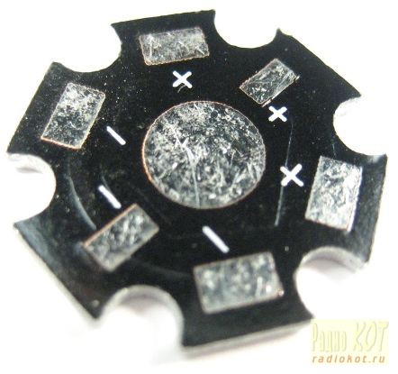
For these LEDs, ready-made radiators “STAR” are available for sale at a cost of $ 0.156:
To obtain a current of up to 700mA to power such powerful LED it was decided to use an existing converter in a burned-out fluorescent lamp. By closing all the terminals of the lamp bulb and winding an additional winding on the inductor on the board, such a converter can be turned into a power source at minimal cost. In fact, a ready-made electronic transformer is obtained from the lamp, it is only necessary to provide a stabilized current to power the LED.
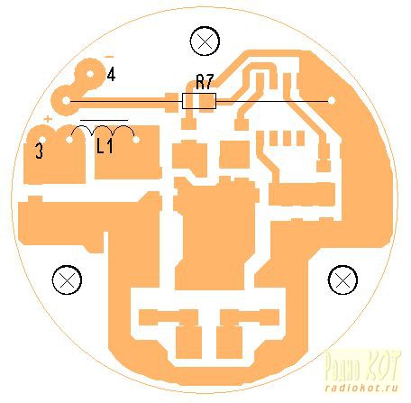
Here is a diagram of an energy-saving lamp, copied directly from the board:
To convert it into an electronic transformer, it is enough to unsolder the bulb, close points 2 and 4 of the board to each other and wind an additional winding on the L2 choke. A rectifier with a filter is connected to the additional winding.
To stabilize the current through the LED, the method proposed in was initially tested. Its essence lies in winding an additional winding on the control transformer T1 and shunting it with opening field-effect transistors to disrupt the oscillations of the converter when the output voltage (current) is exceeded. However, nothing good came of it. As the analysis of the operation of the above circuit showed, to restore the oscillations of the converter, it takes about 3 ms to charge the capacitor C3 to the breakdown voltage of the dinistor DB3 (30 V). Even with a very short shunt of the additional winding on T1, the restart time of the converter was about 3 ms. As a result, the control characteristic of the converter is incomplete. When trying to only “slightly” reduce the output voltage, for example, to 90 ... 95%, short positive pulses with relatively long dips of 3 ms immediately appeared at the output of the rectifier filter (from the additional power winding of the inductor) instead of a constant voltage. Those. control limits were possible only in the initial small section of the converter operation.
Therefore, another circuit solution was applied, shown in the figure below:

An additional circuit is a switching current stabilizer, assembled without the use of specialized microcircuits on a widespread cheap element base. An additional winding is wound on the lamp inductor, the voltage from which is supplied to the diode bridge VD1 ... VD4 with filter capacitors C1, C3. The use of a bridge circuit is caused by the difficulty of winding twice as many turns on the L2 inductor with a tap from the middle due to limited space.
On the DA1 chip, a +2.5 V voltage regulator is made to power the DA2 comparator and the resistive reference voltage driver R5, R6. Resistor R7 with a resistance of 0.1 ohms acts as a current sensor. A power switch is assembled on transistors VT1, VT2. In the initial state, when power is applied, while the current through the HL1 LED has not yet flowed, the output of the comparator DA2 is high, VT1 is closed and VT2 is open through R4. Through the inductor L1, an increasing current flows into the load. When the reference voltage is exceeded at the inverting input of the comparator DA2, the latter switches to a state with a low level at the output. VT1 abruptly opens and shunts transition VT2, closing the latter and causing a self-induction current in the circuit VD5, L1, C4, C5, HL1, R7. After reducing the voltage at the inverting input of the comparator DA2 as C4, C5 are discharged, the latter again goes into a state with a high output level. VT1 closes, VT2 opens and the whole process repeats. The oscillation frequency at an input voltage of 7 V is 50 ... 70 kHz. The measured efficiency of the switching current stabilizer was 86%.
The value of the current through the LED is chosen equal to 0.6 A for a more gentle operation and less heating.
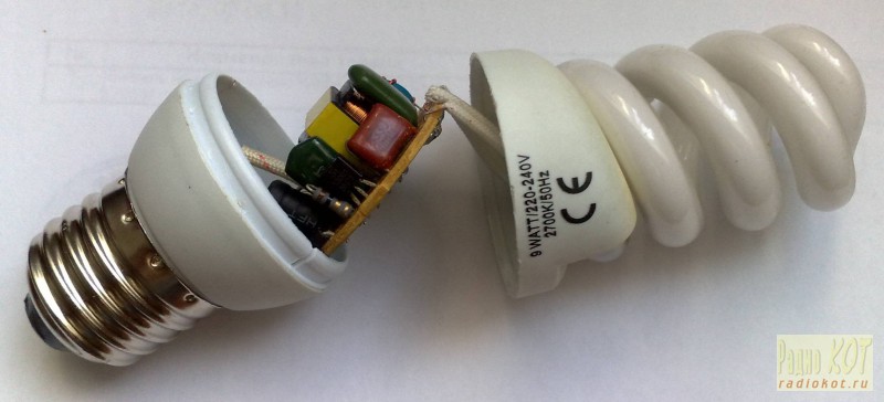
Energy-saving lamp conversion procedure
The lamp housing is opened with a flat screwdriver (fastening with latches). The upper part with the flask is carefully disposed of (Attention! Mercury vapor in the flask! If the flask is damaged, it is necessary to treat the surrounding objects in contact with a solution of potassium permanganate). Capacitor C5 can be removed from the board, because. he is not involved in the work. Shorted points 2 and 4 on the board. The L2 inductor is soldered and an additional winding of 14 turns is wound with the MGTF-0.1 wire (almost until the gap is completely filled). It is better to use MGTF for good galvanic isolation.

The throttle is soldered into place. It doesn't hurt to check the C3 electrolyte with an ESR meter. If possible, it is better to replace it with a new one with a capacity of 4.7 ... 10 microfarads x 400 V (105 ° C). This will reduce the 100 Hz ripple at the converter output.
After that, a board is made of one-sided foil fiberglass:

For the manufacture of inductor L1, a ready-made DP2-0.1 for 100 μH was used. A regular winding was removed from it with a knife and a new one was wound with PEV2 wire ø0.3 mm evenly along the entire length of the core in 3 layers. Choke inductance 51 uH. You can also use a purchased choke of suitable dimensions with an inductance of 47 μH and a current of at least 1.5 ... 2 A.
You can try replacing the VT2 IRLML6401 transistor with an IRLML6402.
Diodes VD1 ... VD4 SS14 can be replaced with any suitable SMD Schottky diodes, rated for a current of at least 1A and a reverse voltage of 30 ... 40V, for example SM5818, SM5819.
Diode VD5 SS24 (2A, 40V) replace with SS22, 10BQ015 or similar.
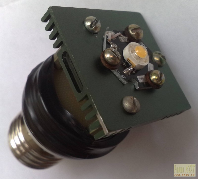
As mentioned above, the LED is soldered onto a ready-made “STAR” radiator, which, in turn, is installed on a more massive radiator. In this case, a heatsink from an old motherboard was used. With cut-off “ears” of fastening, its dimensions are 37.5 x 37.5 x 6 mm. The radiator is attached to an additional board on 3 M3x15 racks. The board itself is attached to the top of the lamp housing with several turns of electrical tape. Between the standard and additional boards, it is necessary to lay an insulating gasket cut, for example, from non-foil fiberglass.


It is desirable to turn on the modified lamp for the first time with a load in the form of a 5-watt resistor with a resistance of 5 ... 6 Ohms with an ammeter connected in series. It is safer to turn on the lamp to a 220 V network through a conventional 40 ... 60 W incandescent bulb. In normal operation, its spiral should not glow. On the VD5 cathode, rectangular pulses with a frequency of 50 ... 70 kHz should be present. The voltage at C3 should be 5 ... 8 V, the current through the load is 0.6 A. More precisely, the current value can be set by selecting the resistance of the resistor R5. After that, you can connect the LED.
Subjectively, the brightness of the glow of the lamp modified in this way corresponds to a 30 W incandescent lamp. The hue is warm, but compared to an incandescent lamp, it is a little colder. The measured power consumption was 3.3 W:

The cost of the second version of the LED lamp was about 3.2 $.
Literature:
1) How to stabilize an electronic transformer. A.E. Shufotinsky. Radioamator No. 1/2010.
ID: 1371
|
How do you like this article? |
Energy-saving lamps are widely used in everyday life and in production, over time they become unusable, and meanwhile, many of them can be restored after a simple repair. If the lamp itself is out of order, then from the electronic "stuffing" you can make quite powerful block supply for any desired voltage.
What does a power supply from an energy-saving lamp look like?
In everyday life, a compact, but at the same time powerful low-voltage power supply is often required; this can be done using a failed energy-saving lamp. In lamps, lamps most often fail, and the power supply remains in working order.
In order to make a power supply, you need to understand the principle of operation of the electronics contained in an energy-saving lamp.
Advantages of switching power supplies
In recent years, there has been a clear trend towards moving away from classic transformer power supplies to switching ones. This is due, first of all, to the large disadvantages of transformer power supplies, such as large mass, low overload capacity, low efficiency.
The elimination of these shortcomings in switching power supplies, as well as the development of the element base, made it possible to widely use these power units for devices with power from a few watts to many kilowatts.
Power Supply Diagram
The principle of operation of a switching power supply in an energy-saving lamp is exactly the same as in any other device, for example, in a computer or TV.
In general terms, the operation of a switching power supply can be described as follows:
- Alternating mains current is converted into direct current without changing its voltage, i.e. 220 V.
- The pulse-width converter on transistors converts constant pressure into rectangular pulses, with a frequency of 20 to 40 kHz (depending on the lamp model).
- This voltage is fed through the choke to the lamp.
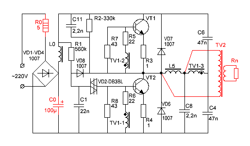
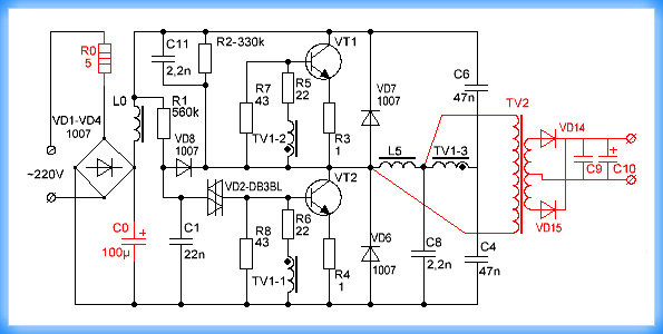
Consider the scheme and operation of the switching lamp power supply (figure below) in more detail.
Scheme of the electronic ballast of an energy-saving lamp
The mains voltage is supplied to the bridge rectifier (VD1-VD4) through a limiting resistor R 0 of small resistance, then the rectified voltage is smoothed on the filtering high-voltage capacitor (C 0), and through the smoothing filter (L0) is fed to the transistor converter.
The start of the transistor converter occurs at the moment when the voltage across the capacitor C1 exceeds the opening threshold of the VD2 dinistor. This will start the generator on transistors VT1 and VT2, due to which auto-generation occurs at a frequency of about 20 kHz.
Other circuit elements such as R2, C8 and C11 play a supporting role, making it easier to start the generator. Resistors R7 and R8 increase the closing speed of the transistors.
And the resistors R5 and R6 serve as limiting resistors in the transistor base circuits, R3 and R4 protect them from saturation, and in the event of a breakdown they play the role of fuses.
Diodes VD7, VD6 are protective, although in many transistors designed to work in such devices, such diodes are built-in.
TV1 is a transformer, from its windings TV1-1 and TV1-2, the feedback voltage from the generator output is fed into the base transistor circuits, thereby creating conditions for the generator to work.
In the figure above, the parts to be removed when reworking the block are highlighted in red, points A–A` must be connected with a jumper.
Block rework
Before proceeding with the alteration of the power supply, you should decide what current power you need to have at the output, the depth of modernization will depend on this. So, if a power of 20-30 W is required, then the alteration will be minimal and will not require much intervention in the existing circuit. If you need to get a power of 50 or more watts, then a more thorough upgrade will be required.
It should be borne in mind that the output of the power supply will be a constant voltage, not an alternating one. Get from such a power supply AC voltage 50 Hz is not possible.
We determine the power
Power can be calculated using the formula:
Р – power, W;
I - current strength, A;
U - voltage, V.
For example, let's take a power supply with the following parameters: voltage - 12 V, current - 2 A, then the power will be:
Taking into account the overload, 24-26 W can be accepted, so that the manufacture of such a unit will require minimal intervention in the circuit of a 25 W energy-saving lamp.
New details

Adding New Parts to a Schematic
Added parts are highlighted in red, these are:
- diode bridge VD14-VD17;
- two capacitors C 9, C 10;
- additional winding placed on the L5 ballast choke, the number of turns is selected empirically.
The added winding to the inductor plays another important role of an isolation transformer, preventing mains voltage from entering the output of the power supply.
To determine the required number of turns in the added winding, do the following:
- a temporary winding is wound on the inductor, about 10 turns of any wire;
- connected to a load resistance, with a power of at least 30 W and a resistance of about 5-6 ohms;
- plug into the network, measure the voltage at the load resistance;
- the resulting value is divided by the number of turns, find out how many volts per 1 turn;
- calculate the required number of turns for a permanent winding.
A more detailed calculation is given below.
Test inclusion of a converted power supply
After that, it is easy to calculate the required number of turns. To do this, the voltage that is planned to be received from this block is divided by the voltage of one turn, the number of turns is obtained, about 5-10% is added to the result obtained in reserve.
W \u003d U out / U vit, where
W is the number of turns;
U out - the required output voltage of the power supply;
U vit - voltage per turn.

Winding an additional winding on a standard choke
The original inductor winding is under mains voltage! When winding an additional winding over it, it is necessary to provide interwinding insulation, especially if a PEL-type wire is wound in enamel insulation. For winding insulation, you can use PTFE thread sealing tape, which is used by plumbers, its thickness is only 0.2 mm.
The power in such a block is limited by the overall power of the transformer used and the allowable current of the transistors.
High Power Power Supply
This will require a more complex upgrade:
- additional transformer on a ferrite ring;
- replacement of transistors;
- installation of transistors on radiators;
- increasing the capacitance of some capacitors.
As a result of such an upgrade, a power supply unit with a power of up to 100 W is obtained, with an output voltage of 12 V. It is capable of providing a current of 8-9 amperes. This is enough to power, for example, a medium power screwdriver.
The diagram of the upgraded power supply is shown in the figure below.
100 W power supply
As you can see in the diagram, the resistor R 0 has been replaced with a more powerful one (3-watt), its resistance has been reduced to 5 ohms. It can be replaced by two 2-watt 10 ohm ones by connecting them in parallel. Further, C 0 - its capacitance is increased to 100 microfarads, with an operating voltage of 350 V. If it is undesirable to increase the dimensions of the power supply, then you can find a miniature capacitor of this capacity, in particular, you can take it from a soap camera.
To ensure reliable operation of the unit, it is useful to slightly reduce the values of the resistors R 5 and R 6, up to 18–15 Ohms, and also increase the power of the resistors R 7, R 8 and R 3, R 4. If the generation frequency turns out to be low, then the values \u200b\u200bof the capacitors C 3 and C 4 - 68n should be increased.
The most difficult may be the manufacture of the transformer. For this purpose, in impulse blocks, ferrite rings of appropriate sizes and magnetic permeability are most often used.
The calculation of such transformers is quite complicated, but there are many programs on the Internet with which it is very easy to do this, for example, "Lite-CalcIT Pulse Transformer Calculation Program".
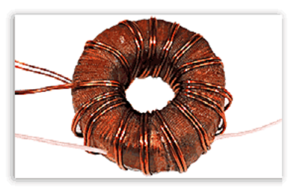
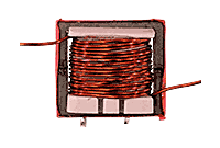
What does a pulse transformer look like?
The calculation carried out using this program gave the following results:
For the core, a ferrite ring is used, its outer diameter is 40, its inner diameter is 22, and its thickness is 20 mm. The primary winding with PEL wire - 0.85 mm 2 has 63 turns, and two secondary ones with the same wire - 12.
The secondary winding must be wound in two wires at once, while it is advisable to first slightly twist them together along the entire length, since these transformers are very sensitive to the asymmetry of the windings. If this condition is not observed, then the VD14 and VD15 diodes will heat up unevenly, and this will further increase the asymmetry, which, in the end, will disable them.
But such transformers easily forgive significant errors when calculating the number of turns, up to 30%.
Since this circuit was originally designed to work with a 20 W lamp, transistors 13003 were installed. In the figure below, position (1) is medium power transistors, they should be replaced with more powerful ones, for example, 13007, as in position (2). They may have to be installed on a metal plate (radiator), with an area of \u200b\u200babout 30 cm 2.

Trial
A trial run should be carried out with some precautions in order not to damage the power supply:
- The first test switching on should be done through a 100 W incandescent lamp in order to limit the current to the power supply.
- Be sure to connect a load resistor of 3-4 ohms, with a power of 50-60 watts, to the output.
- If everything went well, let it run for 5-10 minutes, turn it off and check the degree of heating of the transformer, transistors and rectifier diodes.
If no mistakes were made during the replacement of parts, the power supply should work without problems.
If the trial run showed the unit to work, it remains to test it in full load mode. To do this, reduce the resistance of the load resistor to 1.2-2 ohms and plug it into the network directly without a light bulb for 1-2 minutes. Then turn off and check the temperature of the transistors: if it exceeds 60 0 C, then they will have to be installed on radiators.
As a radiator, you can use both a factory radiator, which will be the most correct solution, and an aluminum plate with a thickness of at least 4 mm and an area of 30 sq.cm. Under the transistors it is necessary to put a mica gasket, they must be fixed to the radiator with screws with insulating bushings and washers.
Lamp block. Video
How to make a switching power supply from an economy lamp, see the video below.
You can make a switching power supply from the ballast of an energy-saving lamp with your own hands, having minimal skills in working with a soldering iron.