Star news


Fiber optic connectors. Optical connectors: purpose, types, characteristics of connectors
IC "Telecom-Service" offers services for the design, installation and service support of corporate communications built on the basis of fiber-optic lines. The company’s unique offer is an integrated approach to the creation of corporate telecommunications and information systems. In addition to installing optics, we effectively implement the creation of office PBXs and call centers (including those based on VOIP), as well as the creation of data processing centers and storage systems. Attention: equipment is supplied only as part of the project, there is no retail sale.
It is obvious that in an ideal optical information transmission system, the light flux should pass unhindered from the source to the photodetector. Optical fiber is nothing more than the same signal propagation path. It is not possible to stretch a single fiber from the source to the receiver. The technological length of the fiber usually does not exceed several kilometers. And if this problem can still be solved by welding light guides, then ensuring the mobility of the local optical subnetwork is achieved only with the use of cross-connect equipment. Problems of transmitting light waves from one piece of fiber to another cannot be avoided. For multiple and simple connection of optical links, light guides can be terminated with optical connectors. Considering that modern light guides are micron technologies, terminating fibers with optical connectors is a challenging task.
Losses in optical connectors
Let us describe the problems that arise when a signal passes from one fiber to another. Loss of power or attenuation of the optical wave occurs when the optical fibers are not accurately aligned. In this case, some of the rays simply do not pass into the next light guide, or enter at an angle that is more critical. When the physical contact of the fibers is incomplete, an air gap is formed. In this connection, the effect of return losses arises. When passing through transparent media with different densities, some of the rays are reflected in the opposite direction. When they reach the resonator, they are amplified and cause signal distortion.
Non-ideal fiber geometry also contributes to power loss. This may be due to the ellipticity of the fiber and the non-centricity of its core. The end of the light guide itself may contain deformations: chips and roughness, which in turn reduces the working surface of contact of the fibers.

Optical connector tips
Thus, it is necessary to align both light guides accurately and tightly. To ensure the safety of fragile fibers during repeated alignment, their end sections are placed in ceramic, plastic or steel tips. Most tips are cylindrical with a diameter of 2.5 mm. Conical designs are available, and LC connectors have a tip with a diameter of 1.25 mm.Inside the tips there is a channel into which the light guide, cleared of its sheath, is inserted and fixed chemically or mechanically. When removing the protective coating, both special mechanical tools and chemically active solutions can be used. Inside the tip, the light guide can be fixed both along the entire length of the channel (more often these are glue-based methods) and at the point where the fiber enters the tip (mechanical methods). The process of mechanical fixation takes much less time (up to several minutes) and is based on “pressing” the fiber using polymer materials. But it is less reliable and short-lived. The chemical method speaks for itself. Most often, the fixing composition in this technology is epoxy solutions, as they are the most reliable. However, the period of complete thickening of such a composition is very long - up to a day. Therefore, if faster installation of connectors is required, other components or special drying ovens can be used.
After installing the light guide into the connector, it is necessary to grind the end of the tip. The protruding excess fiber is removed with special tools. The basic principle is to cut and break off the light guide, after which you can begin to directly polish the surface.
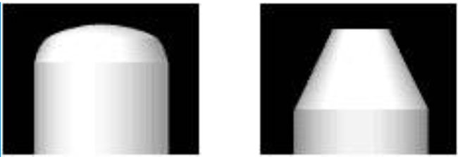
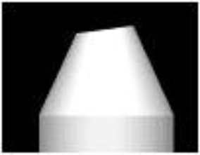
Of particular interest is the shape of the ends of the tips. Their processing is a whole art. The simplest version of the end is a flat shape. It is characterized by large return losses, since the likelihood of an air gap in the vicinity of the fibers is high. There are enough irregularities even in the non-working part of the end surface. Therefore, convex ends are more often used (the radius of rounding is about 10-15 mm). With good centering, tight contact of the light guides is guaranteed, which means there is more likely to be no air gap. An even more advanced solution is to round the end at an angle of several degrees. Rounded ends are less dependent on deformations generated when connecting connectors, so such tips can withstand a larger number of connections (from 100 to 1000).
The material of the tip is also important. The overwhelming majority of connectors are built on the basis of ceramic tips, as they are more durable.
After terminating the light guides with connectors, it is necessary to analyze the quality of the tip surface. Microscopes are most often used for this. Professional devices have a magnification factor of hundreds of times and are equipped with special illumination from various angles. They may also have an interface for connecting to additional measuring equipment.

According to the TIA/EIA 568A standard, the return loss for multimode fiber in optical connectors should not exceed -20 dB, and for single-mode fiber -26 dB. Based on the magnitude of return losses, connectors are divided into classes
| Type | Losses | Type | Losses |
| PC | less than 30 dB | Ultra PC | less than 50 dB |
| Super PC | less than 40 dB | Angled PC | less than 60 dB |
PC is an abbreviation of the English Physical Contact.
Connecting optical connectors
Fundamentally, the connection of two optical connectors cross-connect equipment is built according to the following scheme:The platform for installing the connectors is the socket. The connectors included in it are fixed in such a way that the axes of their tips are centered, parallel and pressed tightly. Such sockets are usually installed in patch panels or mounting box inserts.
| Connector type | Tip | Loss (dB) at 1300 nm | |
| Multimode | Singlemode | ||
| ST | Ceramics | 0.25 | 0.3 |
| S.C. | Ceramics | 0.2 | 0.25 |
| L.C. | Ceramics | 0.1 | 0.1 |
| F.C. | Ceramics | 0.2 | 0.6 |
| FDDI | Ceramics | 0.3 | 0.4 |
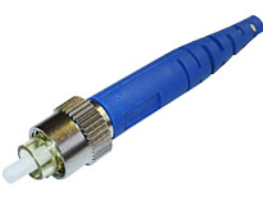
ST connector
Connectors differ not only in the tips used, but also in the type of fixation of the structure in the socket. The most common representative in local optical networks is the ST-type connector (from the English Straight Tip). The ceramic tip has a cylindrical shape with a diameter of 2.5 mm with a rounded end. Fixation is carried out by rotating the frame around the axis of the connector, while there is no rotation of the connector base (theoretically) due to the groove in the socket connector. The guide frames, engaging with the stops of the ST-socket when rotating, press the structure into the socket. The spring element provides the necessary pressure.The weak point of the ST technology is the rotational movement of the frame when connecting/disconnecting the connector. It requires a large living space for one link, which is important in multiport cable systems. Moreover, there is no rotation of the tip only in theory. Even minimal changes in the position of the latter entail an increase in losses in optical connections. The tip protrudes from the base of the structure by 5-7 mm, which leads to its contamination.
SC connector
The weaknesses of ST connectors are currently being resolved through the use of SC technology (from the English Subscriber Connector). The cross-section of the body has a rectangular shape. The connector is connected/disconnected by a translational movement along the guides and secured with latches. The ceramic tip also has a cylindrical shape with a diameter of 2.5 mm with a rounded end (some models have a beveled surface). The tip is almost completely covered by the body and is therefore less susceptible to contamination than in the ST design. The absence of rotational movements causes more careful pressing of the tips.In some cases, SC connectors are used in a duplex version. The design may have clamps for pairing connectors, or special brackets may be used to group housings. Connectors with single-mode fiber are usually blue in color, while connectors with multi-mode fiber are gray.
LC connector
LC type connectors are a small-sized version of SC connectors. It also has a rectangular body section. The design is made on a plastic base and is equipped with a latch similar to the latch used in modular connectors of copper cable systems. As a result, the connector is connected in a similar way. The tip is made of ceramic and has a diameter of 1.25 mm.
There are both multimode and single-mode connector options. The niche of these products is multiport optical systems.
FC connector
In single-mode systems, there is another type of connector - FC. They are characterized by excellent geometric characteristics and high tip protection.FDDI connector
To connect a duplex cable, not only paired SC connectors can be used. FDDI connectors are often used for these purposes. The design is made of plastic and contains two ceramic tips. To avoid incorrect connection of the link, the connector has an asymmetrical profile.FDDI technology provides for four types of ports used: A, B, S and M. The problem of identifying the corresponding links is solved by providing connectors with special inserts, which can vary in color or contain letter indices.
This type is mainly used to connect terminal equipment to optical networks.
MT-RJ connectors
Guaranteed parameters of cable assemblies:
- Direct losses<0.5 дБ (типичное значение - 0.25 дБ для ММ)
- Wiring in buildings (horizontal and backbone)
- Telecommunication networks
Peculiarities:
- Latch size and design similar to RJ-45
- Duplex ferul
- Low cost
- High port density
- ISO/IEC 11801 and TIA/EIA 568A compliant
- Low direct losses:
< 0.22 дБ для ММ
< 0.19 дБ для ОМ
The development of the MT-RJ connector was aimed at solving the following problems: small size, low cost and ease of installation. The use of the MT-RJ connector doubles the port density of standard connectors and makes it ideal for use in fiber-to-the-desk applications. The connector design complies with TIA requirements.
The MT-RJ connector uses an improved version of the industry standard RJ-45 connector. It is the small size and convenience of a latch similar to RJ-45 that determine the advantages of this connector when used in horizontal wiring to the workplace.
A feature of the MT-RJ system from Molex is the use of different PNs for the male (with guide pins protruding from the ferrule) and female (with holes for the pins) connectors. There are two modifications of the adapter, one of which is installed in the socket for a simplex SC adapter.
Quality and characteristics
Materials provided by AESP, a well-known manufacturer of networking and communications equipment, developer of the SygnaMax cable system.
Optical connectors(connectors) are used when terminating optical fibers to connect them with passive or active telecommunications equipment.
Today there are a large number of specializedoptical connectors.The most widespreadoptical connectors types SC, FC, ST , having standard sizes and miniature L.C. The principle of operation is the same, only the methods of fixation or the type of attachment to the socket are different.
Optical connector ST type has a tip with a diameter of 2.5 mm with a convex end surface. The plug is fixed to the socket using a spring-loaded bayonet element,turning ¼ turn. The guide frames, engaging with the stops of the ST-socket when rotating, press the structure into the socket. The spring element provides the necessary pressure.
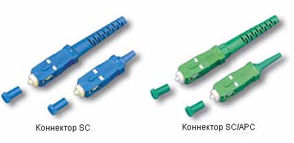
SC type optical connectortype is the most popular among connectors with a rectangular cross-section.Fixation is carried out using a latch with a lock according to the “push-pull” principle.The linear movement of plugging and unplugging makes this connector particularly suitable for 19-inch shelf applications, as it allows for increased port density by bringing the receptacles closer together. The latch only opens when pulled by the housing, which increases operational reliability. An optical SC connector can be combined into a module consisting of several Duplex connectors.

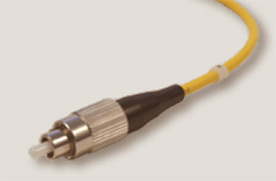
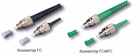
FC type optical connectorfixed with a threaded connection. oriented , mainly for use in single-mode long-distance communication lines, specialized systems and cable television networks. The design of the connector provides reliable protection of the ceramic tip from contamination, and the use of a union nut for fixing provides greater tightness of the connection area and reliability of the connection when exposed to vibrations.

Miniature LC type optical connectorsare approximately half the size of regular options SC, FC, ST with a tip diameter of 1.25 mm, instead of the standard 2.5 mm. This allows for high-density patch panel mounting and dense rack-mount layouts. The connector is fixed using a clamping mechanism.


We are also pleased to offer you connectors differing in installation method:
One of the simplest methods for installing connectors on fiber is adhesive. This method uses epoxy resin to secure the fiber into the connector core.
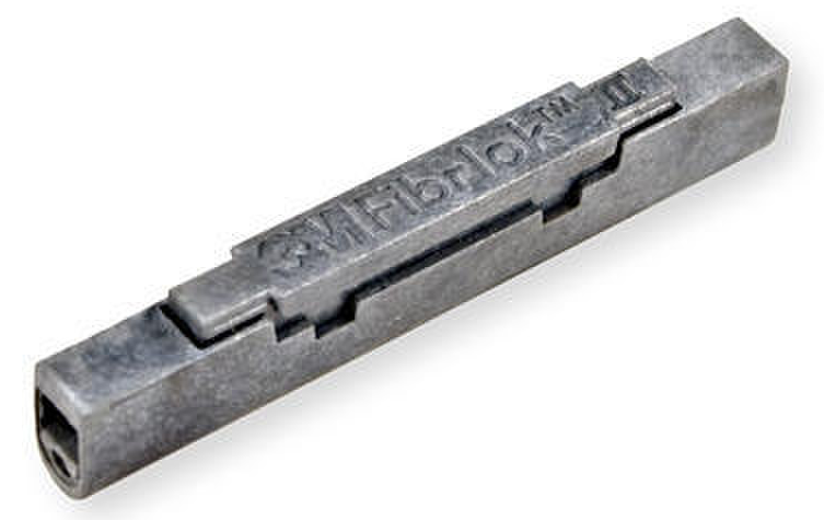
Quick connector allows you to easily and quickly terminate optical cables. In the store you can find everything you need to install a quick connector.
They are designed for quick termination of optical cables using the unique “Splice-On” technology using the Ilsintech Swift F1 welding machine.
The main enemies of optical connectors that prevent high-speed data transfer are dirt, dust and other contaminants.
This extensive article will provide you with detailed, organized information on passive optical components. After reading, you will get a complete understanding of why, by what parameters and how to select components for fiber-optic communication lines.
Various manufacturers over the years have developed several dozen types of optical connectors (connectors) and pass-through adapters for connecting them, but only 4 of them are most widespread: ST, FC, SC, LC. The remaining connectors that ever existed are rarely used or have been discontinued altogether.
It should be noted that there is currently no document standardizing the use of any types of connectors. In this regard, depending on the industry of application, certain types of connectors are more popular.
Main types of optical connectors
ST "Straight Tip" connector
It has a metal bayonet design, the diameter of the ceramic tip is 2.5 mm. The connector was previously popular mainly in networks using multimode optical fiber. However, it is not recommended for use now, since this type of connector lacks the advantages that others have:
the possibility of manufacturing a duplex connector in which it would be physically impossible to confuse the location of the fibers for transmission and reception;
high reliability, stability under vibration loads;
compactness and ease of switching.
FC Ferrule Connector
The design is similar to the ST connector, the diameter of the ceramic tip is 2.5 mm, but instead of a bayonet a metal threaded connection is used. Today, the connector is actively used in active equipment and measuring instruments, due to its high reliability and resistance to vibration.
It is mainly used in long-distance fiber-optic lines (backbone fiber-optic lines), however, on access networks, in SCS and data centers, its use is limited due to the complexity of switching and the impossibility of manufacturing a duplex connector.
SC "Subscriber Connector"
Note: The designation SC-D may also be used to indicate that the connector is a duplex, keyed connector.

The connector is most widespread due to its ease of switching (using direct snapping) and the possibility of creating a duplex connector. The SC connector consists of an inner and outer housing, the diameter of the ceramic tip is 2.5 mm. It is installed in the pass-through adapter without rotation, which is convenient for switching. The plastic design is quite durable, found in active equipment and widely used in SCS and city-scale data transmission networks, although the connector is not one of the compact ones. SC duplex connectors are most often used, but simplex connectors can also be used.
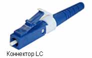
LC "Lucent Connector"
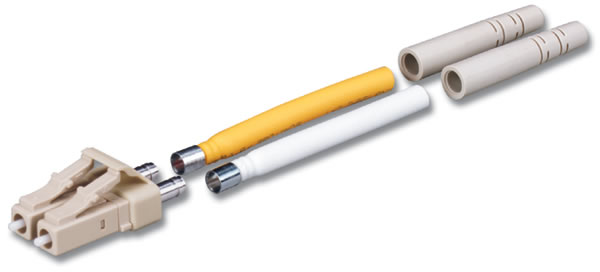
Unlike the previously listed connectors, the diameter of the ceramic tip is 1.25 mm and therefore requires more careful handling. Due to their more compact size, LC connectors have become increasingly popular in both active equipment and passive optical cabinets and shelves, especially in high density. The connector is classified as SFF - Small Form factor, in which the external dimensions of the connector fit into the seat of an 8-position modular RJ-45 connector. The connector is installed into the pass-through adapter without rotation, by direct snapping. Duplex LC connectors are most often used, but simplex connectors can also be used. The connector body is made of plastic.
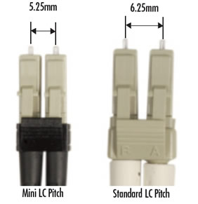
Attention! There is a smaller version of the LC duplex connector, in which the two housings are spaced closer together than the standard connector. Mini connectorsL.C.and mini-throughs are not compatible with duplex componentsL.C.standard connector!
Among the variety of connectors in SCS, preference is given to duplex SC and LC connectors with a key that prevents incorrect insertion of the connector into the pass-through adapter - thereby ensuring the correct polarity of the optical connection. New active equipment models and data centers almost always use LC connectors due to their compact size.
Single-mode and multimode connectors and pass-through adapters
All of the listed connectors are available in versions for single-mode fiber 9/125 microns and for multimode fibers 50/125 or 62.5/125 microns. The design of the connectors is fundamentally the same, however, for single-mode systems they are manufactured with the strictest tolerances, while for multimode systems connectors with wider limits on the accuracy of tip drilling are suitable ( ferrule) and the manufacture of other structural elements. The same applies to feed-through adapters: feed-throughs for single-mode systems are subject to more stringent requirements for manufacturing accuracy.
Types of polishing
For the bulk of optical connectors, the end surface is located at an angle of 90º to the longitudinal axis of the light guide. The end of the ceramic tip may have a certain rounding, have a chamfer of one size or another, but the area where the light guides touch is flat. Polishing quality may vary:
PC - Physical Contact- basic quality, acceptable for ordinary applications in SCS and local networks for not very long distances and speeds up to 1 Gbit/s inclusive. Reflectivity is about -35 dB.
SPC - Super Physical Contact- improved quality (primarily due to machine polishing), reflectivity -40 ÷ -45 dB or less. This or higher level of polish is used in factory optical cords and pigtails.
UPC - Ultra Physical Contact- maximum quality, only machine polishing with strict quality control, reflectivity -50 ÷ -55 dB or less. Cords with this polish are used for high-precision measurements when testing optical systems and for operating the most demanding applications at speeds of 10 Gbps or more.
PC, UPC and SPC polished connectors are structurally compatible with each other. The overall performance of the system is most affected by the components with the weakest parameters, so it is recommended to select products with the same or higher polish quality.
Angle polished connectors
Angular polished connectors available APC - Angled Physical Contact. In them, the joining surface is deviated by 8º from the usual one, i.e. the angle with the axis of the light guide is 82º. Reflectivity is -65 dB or less.
These connectors provide the best performance available today and minimize back reflections. However, they are not compatible with conventionally polished connectors. Attempting to dock the connectorAPCwith any non-angled connector will cause damage to both! To reduce the risk of erroneous mating, APC connector bodies, their shanks and feed-through adapters are manufactured in bright green.

APC connectors are most widely used in cable television networks and provider lines.
Color options for regular connectors
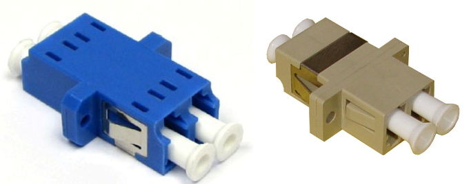
For conventional multimode connectors, it is customary to use black and beige colors for the body and pass-through adapters. Single-mode connectors and pass-through adapters are most often produced in blue.
Note:
- Some manufacturers may manufacture all pass-through adapters to single-mode precision, but it is always recommended to check specifications against datasheets and catalogs.
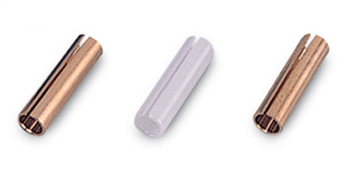
The alignment of the tips when connecting optical connectors is ensured by a centralizer located inside the feed-through adapter. A centralizer is a sleeve made of bronze, brass or ceramic, which has a longitudinal cut along its entire length. The best characteristics are provided by ceramic centralizers; they are made from the same material as ceramic tips ( ferrule) connectors. For high-speed and demanding applications, feed-through adapters with ceramic centralizers are recommended.
Optical patch cords
The cords are selected according to the type of fiber in the system (multimode classes OM1-OM4, single-mode classes OS1-OS2), with a specific type of connector at the ends. The bulk of optical patch cords are duplex. The most popular are duplex connectors LC and SC, but simplex cords are also used. If necessary, cords with different connectors at the ends are used - for example, FC connectors at one end for connecting to active equipment and LC connectors at the other for connecting to an optical cross-connect.
The outer diameter of the cable in optical cords was previously usually 3 mm (or twice 3 mm, if we were talking about zip cords), but recently they are trying to make cables more compact, smaller in diameter (for example, 2 or 1.5 mm) in order to fit optical cabinets and organizers have the maximum possible number of cords and connections. Regardless of the diameter and type of connectors, all optical cords require careful handling. When disconnecting from the ports, the connectors must be covered with protective caps.
A pigtail is a one-way fiber-optic jumper, “half cord” - has a factory-made and tested connector at one end, the other end is not sealed and is intended for connection to an unterminated cable with a welded or mechanical coupling. Unlike optical cords, pigtails do not have an outer cable sheath; a fiber comes out of the connector shank in a dense buffer with a diameter of 900 microns or 250 microns. The design of the shank and the diameter of its hole must correspond to the diameter of the buffer. Shanks designed to be installed on cable with a diameter of 3 mm or less are not intended to be installed on fiber in a buffer of any diameter and cannot provide adequate protection to the fiber.
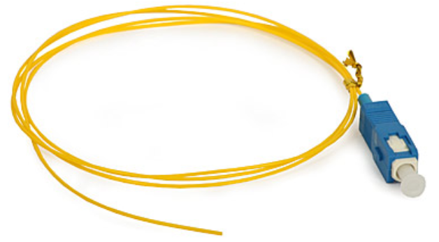
Pigtails are selected according to the type of light guides in the cable to which they are to be connected. The typical length of pigtails is 1 m - this is enough for convenient sealing of the coupling and subsequent laying in the coupling tray (splice plate). Manufacturers may offer pigtails in other lengths, but when ordering, you must consider where and how the fiber will be laid. Since buffered fiber does not have an outer cable sheath, it is critical that it maintains a bend radius of at least 25mm and does not risk damage.
Attenuators are designed to artificially attenuate the signal, which is necessary in cases where the optical segments are short and the transmitter produces a too powerful signal. To prevent an excessively powerful signal from entering the receiver input, it is “muted” by installing an attenuator at some point in the segment.
The attenuator must match the installed system in terms of fiber and connector type. In addition, the attenuator is selected depending on the amount of optical loss in decibels that must be introduced into the segment to attenuate the original signal to an acceptable level.
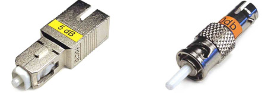
Attenuators are divided into:
active and passive devices;
adjustable and non-adjustable devices;
designs male- female(“male-female”, installed on any connector in the segment) and female- female(“female-female”, installed instead of a pass-through adapter).
Attenuators, like any optical components, require careful handling, the use of protective caps and timely use of fiber optic cleaning products.
Compact devices designed for splicing optical fibers not terminated with connectors. There are two types of couplings available in the market: welded and mechanical.
The welded coupling is a heat-shrinkable tube reinforced with rigid wire - a KDZS sleeve (a set for protecting the welded joint). Welding is performed with a specialized fiber optic welding machine, into which an oven for heat-shrinkable sleeves can be built-in (or included separately).
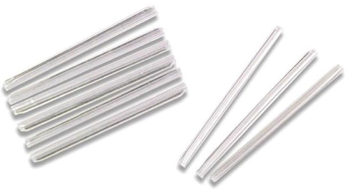
Sophisticated sleeve designs are also used, designed for flat ribbon cables or multi-fiber round cables. Their housings are designed to protect 12 or more welded joints simultaneously.
Mechanical couplings have their own rigid body and do not require the use of a welding machine and KDZS sleeves. The stripped and cleaved fibers are mechanically joined and fixed inside the coupling, and possible voids or unevenness of the chips are filled with a gel whose refractive index is equal to the refractive index of the fiber core. The gel is initially located inside the coupling - this component is fundamentally important for achieving acceptable optical characteristics of the mechanical connection.
All other things being equal, a welded coupling has higher characteristics and leads to significantly lower optical losses than a mechanical one. A well-sealed weld may lose 0.01 dB or less. This method is the leader in popularity and is used both for connecting pigtails to the ends of the cable and for splicing long sections of cable together, especially if the trunk is long and the number of splices is large. In unfavorable conditions (attics, basements, sewer lines, poles and other areas outside buildings), a welded coupling connection certainly outperforms a mechanical one in terms of characteristics, durability and reliability. Mechanical couplings can be used inside buildings where there are no sudden temperature changes, vibration and other unfavorable factors.
Another area of application for mechanical connectors is the rapid repair of fiber-optic lines when a welding machine is unavailable.
In this case, a high speed of repairing damage is ensured at minimal cost (for repairs you need to have: mechanical connectors, a buffer layer stripper, a manual cleaver). The disadvantage of such a connection (not made using technology) is its fragility, because as the immersion gel dries, losses and reflections from the joint site increase. To prevent such a situation, such a connection should be replaced with a welded one within a short period of time (up to a month).
Any couplings require placement inside coupling trays, also called splice cassettes, while the capacity of the trays and the shape of the grooves for laying welded and mechanical couplings are different.

External housings for housing optical couplings
The outer housings that house fiber optic splices are often also referred to as splices, which can lead to some confusion. In this case, we are talking about a durable outer casing designed for installation in outdoor conditions, in sewers, on poles, in trenches (direct burial), in basements, attics and roofs of buildings. The optical coupling connections are located inside the housing; the design ensures their safety and protection from adverse external conditions: dust, wind, rain, snow, temperature changes, etc.
Depending on the cable entry points, the structures are divided into two types:
Material prepared
technical specialists of the SvyazKomplekt company.
Currently, there are many optical connectors, differing in size and shape, methods of attachment and fixation. The choice of optical connector type depends on the active equipment used, the fiber installation tasks and the required accuracy. The main ones are - LC, SC, FC, ST.
The use of an LC optical connector allows for high density mounting in a patch panel or cabinet.
The diameter of the connector tip is 1.25 mm, the material is ceramic. The connector is secured using a clamping mechanism - a latch, similar to an RJ-45 connector, which prevents unexpected disconnection.
When using duplex patch cords, it is possible to connect the connectors with a clip. Used for multimode and singlemode fibers.

The SC connector type is used for both multimode and single-mode fiber. Tip diameter 2.5 mm, material - ceramics. The connector body is made of plastic. The connector is fixed by a translational movement with a snap.
FC connectors are typically used in single-mode connections. The connector body is made of nickel-plated brass. Threaded fixation provides reliable protection against accidental disconnection.

Currently, the ST connector is not widely used due to shortcomings and increased needs for installation density. The connector is fixed by rotating around an axis, similar to a BNC connector.
Many people confuse the types of optical connectors and few can immediately tell which connector has which polish. When communicating with colleagues, you’ve probably often heard phrases like: “well, that little blue connector” or “umm.. green one.” On the Internet, most of the materials are written chaotically and not clearly, in this article we will try to sort everything out.
Types of polishes
It is worth noting that the main problem of optical connectors is optical attenuation; it depends on the misalignment (transverse deviation) of the cores of the optical fibers being joined and has a major impact on the amount of total losses.
Another problem with installing an optical connector at the end of a fiber is optical signal loss, which is caused by some of the transmitted light being reflected back into the fiber to the source of that light, the laser. Reverse reflection (RL -Return Loss) can disrupt the operation of the laser and the structure of the transmitted signal. To prevent/reduce this phenomenon, various types of polishing are used.
Currently there are 4 types of polishing:
Although the last two are mostly used, let's look at each in order.
PC - Physical Contact. In the first variations of polishing, an exclusively flat version of the connector was provided, but life has shown that the flat version makes room for air gaps between the light guides. Subsequently, the ends of the connectors received a slight rounding. The PC class includes hand-polished connectors made using adhesive technology. The disadvantage of this polishing is that a phenomenon called “infrared layer” occurs - in the infrared range, negative changes occur on the end layer. This phenomenon limits the use of connectors with such polishing in high-speed networks (>1G).
SPC - Super Physical Contact. Essentially the same PC, only the polishing itself is of higher quality, because... It is no longer hand-made but machine-made. The radius of the core was also narrowed and the tip material became zirconium. Of course, polishing defects were reduced, but the problem of the infrared layer remained
UPC-Ultra Physically Contact. This polishing is carried out by complex and expensive control systems, as a result of which the problem of the infrared layer was eliminated and the reflection parameters were significantly reduced. This made it possible for connectors with this polish to be used in high-speed networks.
APC - Angled Physically Contact. At the moment, it is believed that the most effective way to reduce the energy of the reflected signal is polishing at an angle of 8-12°. In this design, the reflected light signal propagates at a greater angle than that introduced into the fiber. Bevel polished connectors vary in color and are usually green.

Summary data can be viewed in the table below.
| Dependence of insertion losses on the polishing method | ||
| Series | Insertion attenuation, dB | Back reflection, dB |
| PC | 0,2 | -25 .. -30 |
| SPC | 0,2 | -35 .. 0 |
| UPC | 0,2 | -45 .. 50 |
| APC | 0,3 | -60 .. 70 |
Connector types
Optical FC connector. Developed by NTT. Tip 2.5 mm in diameter with a convex end surface 2 mm in diameter. Fixation is carried out with a threaded union nut. This makes them resistant to vibrations and shocks, which allows them to be used, for example, near railways or on moving objects.
Optical connector ST. Developed by AT&T. Tip 2.5 mm in diameter with a convex end surface 2 mm in diameter. The fiber end is protected by turning it at the time of installation with a side key that fits into the groove of the socket. The fork is secured with a bayonet lock (from the French ba?onnette - bayonet. An example of a bayonet lock is a camera lens mount). The connectors are easy to use and quite reliable, but are sensitive to vibrations.

Optical connector S.C.. The disadvantage of the ST and FC connectors is the rotational movement when turned on; this imposes a limitation on the connection density (it is difficult to screw in when there are a lot of plugs nearby). The SC type is made according to the push-pull principle - press inserted/pulled out. The locking mechanism opens when pulled by the housing. The connector can be pulled out using a force of 40N, whereas when “pulling” ST and FC it is easier to break the fiber itself. Accordingly, it is not recommended to use the SC connector on moving objects.
Optical connector L.C. Developed by Lucent Technologies. Ceramic core with a diameter of 1.25 mm, not connected to a plastic body. It is fixed with a latch, as in the well-known RJ-45. It is the most popular optical connector. A pair of connectors can easily be combined into a duplex.
Conclusion.
The name of the optical patch cord indicates which connectors are installed at the ends, and the type of polishing is indicated through the “/” symbol. If the polish type is not specified, it is a direct polish. For example, a fiber optic patch cord is LC-SC, which means that there will be an LC connector on one end and an SC connector on the other. In the specifications in any store you can select the desired polishing and the necessary connectors.

