Star news


Optical connectors. All about fiber optic cables: options, designs, connectors
IC "Telecom-Service" offers services for the design, installation and service support of corporate communications built on the basis of fiber-optic lines. The company’s unique offer is an integrated approach to the creation of corporate telecommunications and information systems. In addition to installing optics, we effectively implement the creation of office PBXs and call centers (including those based on VOIP), as well as the creation of data processing centers and storage systems. Attention: equipment is supplied only as part of the project, there is no retail sale.
It is obvious that in an ideal optical information transmission system, the light flux should pass unhindered from the source to the photodetector. Optical fiber is nothing more than the same signal propagation path. It is not possible to stretch a single fiber from the source to the receiver. The technological length of the fiber usually does not exceed several kilometers. And if this problem can still be solved by welding light guides, then ensuring the mobility of the local optical subnetwork is achieved only with the use of cross-connect equipment. Problems of transmitting light waves from one piece of fiber to another cannot be avoided. For multiple and simple connection of optical links, light guides can be terminated with optical connectors. Considering that modern light guides are micron technologies, terminating fibers with optical connectors is a challenging task.
Losses in optical connectors
Let us describe the problems that arise when a signal passes from one fiber to another. Loss of power or attenuation of the optical wave occurs when the optical fibers are not accurately aligned. In this case, some of the rays simply do not pass into the next light guide, or enter at an angle that is more critical. When the physical contact of the fibers is incomplete, an air gap is formed. In this connection, the effect of return losses arises. When passing through transparent media with different densities, some of the rays are reflected in the opposite direction. When they reach the resonator, they are amplified and cause signal distortion.
Non-ideal fiber geometry also contributes to power loss. This may be due to the ellipticity of the fiber and the non-centricity of its core. The end of the light guide itself may contain deformations: chips and roughness, which in turn reduces the working surface of contact of the fibers.

Optical connector tips
Thus, it is necessary to align both light guides accurately and tightly. To ensure the safety of fragile fibers during repeated alignment, their end sections are placed in ceramic, plastic or steel tips. Most tips are cylindrical with a diameter of 2.5 mm. Conical designs are available, and LC connectors have a tip with a diameter of 1.25 mm.Inside the tips there is a channel into which the light guide, cleared of its sheath, is inserted and fixed chemically or mechanically. When removing the protective coating, both special mechanical tools and chemically active solutions can be used. Inside the tip, the light guide can be fixed both along the entire length of the channel (more often these are glue-based methods) and at the point where the fiber enters the tip (mechanical methods). The process of mechanical fixation takes much less time (up to several minutes) and is based on “pressing” the fiber using polymer materials. But it is less reliable and short-lived. The chemical method speaks for itself. Most often, the fixing composition in this technology is epoxy solutions, as they are the most reliable. However, the period of complete thickening of such a composition is very long - up to a day. Therefore, if faster installation of connectors is required, other components or special drying ovens can be used.
After installing the light guide into the connector, it is necessary to grind the end of the tip. The protruding excess fiber is removed with special tools. The basic principle is to cut and break off the light guide, after which you can begin to directly polish the surface.
Of particular interest is the shape of the ends of the tips. Their processing is a whole art. The simplest version of the end is a flat shape. It is characterized by large return losses, since the likelihood of an air gap in the vicinity of the fibers is high. There are enough irregularities even in the non-working part of the end surface. Therefore, convex ends are more often used (the radius of rounding is about 10-15 mm). With good centering, tight contact of the light guides is guaranteed, which means there is more likely to be no air gap. An even more advanced solution is to round the end at an angle of several degrees. Rounded ends are less dependent on deformations generated when connecting connectors, so such tips can withstand a larger number of connections (from 100 to 1000).
The material of the tip is also important. The overwhelming majority of connectors are built on the basis of ceramic tips, as they are more durable.
After terminating the light guides with connectors, it is necessary to analyze the quality of the tip surface. Microscopes are most often used for this. Professional devices have a magnification factor of hundreds of times and are equipped with special illumination from various angles. They may also have an interface for connecting to additional measuring equipment.

According to the TIA/EIA 568A standard, the return loss for multimode fiber in optical connectors should not exceed -20 dB, and for single-mode fiber -26 dB. Based on the magnitude of return losses, connectors are divided into classes
| Type | Losses | Type | Losses |
| PC | less than 30 dB | Ultra PC | less than 50 dB |
| Super PC | less than 40 dB | Angled PC | less than 60 dB |
PC is an abbreviation of the English Physical Contact.
Connecting optical connectors
In principle, the connection of two optical connectors of cross-connect equipment is constructed according to the following scheme:The platform for installing the connectors is the socket. The connectors included in it are fixed in such a way that the axes of their tips are centered, parallel and pressed tightly. Such sockets are usually installed in patch panels or mounting box inserts.
| Connector type | Tip | Loss (dB) at 1300 nm | |
| Multimode | Singlemode | ||
| ST | Ceramics | 0.25 | 0.3 |
| S.C. | Ceramics | 0.2 | 0.25 |
| L.C. | Ceramics | 0.1 | 0.1 |
| F.C. | Ceramics | 0.2 | 0.6 |
| FDDI | Ceramics | 0.3 | 0.4 |
ST connector
Connectors differ not only in the tips used, but also in the type of fixation of the structure in the socket. The most common representative in local optical networks is the ST-type connector (from the English Straight Tip). The ceramic tip has a cylindrical shape with a diameter of 2.5 mm with a rounded end. Fixation is carried out by rotating the frame around the axis of the connector, while there is no rotation of the connector base (theoretically) due to the groove in the socket connector. The guide frames, engaging with the stops of the ST-socket when rotating, press the structure into the socket. The spring element provides the necessary pressure.The weak point of the ST technology is the rotational movement of the frame when connecting/disconnecting the connector. It requires a large living space for one link, which is important in multiport cable systems. Moreover, there is no rotation of the tip only in theory. Even minimal changes in the position of the latter entail an increase in losses in optical connections. The tip protrudes from the base of the structure by 5-7 mm, which leads to its contamination.
SC connector
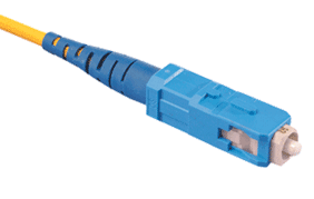
The weaknesses of ST connectors are currently being resolved through the use of SC technology (from the English Subscriber Connector). The cross-section of the body has a rectangular shape. The connector is connected/disconnected by a translational movement along the guides and secured with latches. The ceramic tip also has a cylindrical shape with a diameter of 2.5 mm with a rounded end (some models have a beveled surface). The tip is almost completely covered by the body and is therefore less susceptible to contamination than in the ST design. The absence of rotational movements causes more careful pressing of the tips.In some cases, SC connectors are used in a duplex version. The design may have clamps for pairing connectors, or special brackets may be used to group housings. Connectors with single-mode fiber are usually blue in color, while connectors with multi-mode fiber are gray.
LC connector
LC type connectors are a small-sized version of SC connectors. It also has a rectangular body section. The design is made on a plastic base and is equipped with a latch similar to the latch used in modular connectors of copper cable systems. As a result, the connector is connected in a similar way. The tip is made of ceramic and has a diameter of 1.25 mm.
There are both multimode and single-mode connector options. The niche of these products is multiport optical systems.
FC connector
In single-mode systems, there is another type of connector - FC. They are characterized by excellent geometric characteristics and high tip protection.FDDI connector
To connect a duplex cable, not only paired SC connectors can be used. FDDI connectors are often used for these purposes. The design is made of plastic and contains two ceramic tips. To avoid incorrect connection of the link, the connector has an asymmetrical profile.FDDI technology provides for four types of ports used: A, B, S and M. The problem of identifying the corresponding links is solved by providing connectors with special inserts, which can vary in color or contain letter indices.
This type is mainly used to connect terminal equipment to optical networks.
MT-RJ connectors
Guaranteed parameters of cable assemblies:
- Direct losses<0.5 дБ (типичное значение - 0.25 дБ для ММ)
- Wiring in buildings (horizontal and backbone)
- Telecommunication networks
Peculiarities:
- Latch size and design similar to RJ-45
- Duplex ferul
- Low cost
- High port density
- ISO/IEC 11801 and TIA/EIA 568A compliant
- Low direct losses:
< 0.22 дБ для ММ
< 0.19 дБ для ОМ
The development of the MT-RJ connector was aimed at solving the following problems: small size, low cost and ease of installation. The use of the MT-RJ connector doubles the port density of standard connectors and makes it ideal for use in fiber-to-the-desk applications. The connector design complies with TIA requirements.
The MT-RJ connector uses an improved version of the industry standard RJ-45 connector. It is the small size and convenience of a latch similar to RJ-45 that determine the advantages of this connector when used in horizontal wiring to the workplace.
A feature of the MT-RJ system from Molex is the use of different PNs for the male (with guide pins protruding from the ferrule) and female (with holes for the pins) connectors. There are two modifications of the adapter, one of which is installed in the socket for a simplex SC adapter.
Quality and characteristics
Materials provided by AESP, a well-known manufacturer of networking and communications equipment, developer of the SygnaMax cable system.
Many people confuse the species optical connectors and right off the bat, few people can tell which connector has which polish. When communicating with colleagues, you’ve probably often heard phrases like: “well, that little blue connector” or “umm.. green one.” On the Internet, most of the materials are written chaotically and not clearly, in this article we will try to sort everything out.
Types of polishes
It is worth noting that the main problem of optical connectors is optical attenuation; it depends on the misalignment (transverse deviation) of the cores of the optical fibers being joined and has a major impact on the amount of total losses.
Another problem with installing an optical connector at the end of a fiber is optical signal loss, which is caused by some of the transmitted light being reflected back into the fiber to the source of that light, the laser. Reverse reflection (RL -Return Loss) can disrupt the operation of the laser and the structure of the transmitted signal. To prevent/reduce this phenomenon, various types of polishing are used.
Currently there are 4 types of polishing:
Although the last two are mostly used, let's look at each in order.
PC - Physical Contact. In the first variations of polishing, an exclusively flat version of the connector was provided, but life has shown that the flat version makes room for air gaps between the light guides. Subsequently, the ends of the connectors received a slight rounding. The PC class includes hand-polished connectors made using adhesive technology. The disadvantage of this polishing is that a phenomenon called “infrared layer” occurs - in the infrared range, negative changes occur on the end layer. This phenomenon limits the use of connectors with such polishing in high-speed networks (>1G).
SPC - Super Physical Contact. Essentially the same PC, only the polishing itself is of higher quality, because... It is no longer hand-made but machine-made. The radius of the core was also narrowed and the tip material became zirconium. Of course, polishing defects were reduced, but the problem of the infrared layer remained
UPC-Ultra Physically Contact. This polishing is carried out by complex and expensive control systems, as a result of which the problem of the infrared layer was eliminated and the reflection parameters were significantly reduced. This made it possible for connectors with this polish to be used in high-speed networks.
APC - Angled Physically Contact. At the moment, it is believed that the most effective way to reduce the energy of the reflected signal is polishing at an angle of 8-12°. In this design, the reflected light signal propagates at a greater angle than that introduced into the fiber. Bevel polished connectors vary in color and are usually green.

Summary data can be viewed in the table below.
| Dependence of insertion losses on the polishing method | ||
| Series | Insertion attenuation, dB | Back reflection, dB |
| PC | 0,2 | -25 .. -30 |
| SPC | 0,2 | -35 .. 0 |
| UPC | 0,2 | -45 .. 50 |
| APC | 0,3 | -60 .. 70 |
Connector types
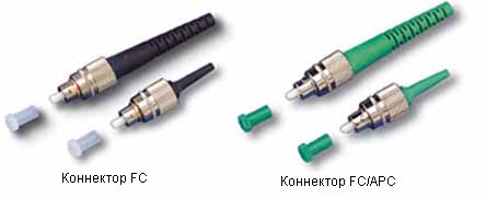
Optical FC connector. Developed by NTT. Tip 2.5 mm in diameter with a convex end surface 2 mm in diameter. Fixation is carried out with a threaded union nut. This makes them resistant to vibrations and shocks, which allows them to be used, for example, near railways or on moving objects.
Optical connector ST. Developed by AT&T. Tip 2.5 mm in diameter with a convex end surface 2 mm in diameter. The fiber end is protected by turning it at the time of installation with a side key that fits into the groove of the socket. The fork is secured with a bayonet lock (from the French ba?onnette - bayonet. An example of a bayonet lock is a camera lens mount). The connectors are easy to use and quite reliable, but are sensitive to vibrations.

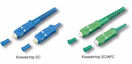
Optical connector S.C.. The disadvantage of the ST and FC connectors is the rotational movement when turned on; this imposes a limitation on the connection density (it is difficult to screw in when there are a lot of plugs nearby). The SC type is made according to the push-pull principle - press inserted/pulled out. The locking mechanism opens when pulled by the housing. The connector can be pulled out using a force of 40N, whereas when “pulling” ST and FC it is easier to break the fiber itself. Accordingly, it is not recommended to use the SC connector on moving objects.
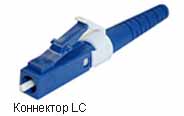
Optical connector L.C. Developed by Lucent Technologies. Ceramic core with a diameter of 1.25 mm, not connected to a plastic body. It is fixed with a latch, as in the well-known RJ-45. It is the most popular optical connector. A pair of connectors can easily be combined into a duplex.
Conclusion.
The name of the optical patch cord indicates which connectors are installed at the ends, and the type of polishing is indicated through the “/” symbol. If the polish type is not specified, it is a direct polish. For example, a fiber optic patch cord is LC-SC, which means that there will be an LC connector on one end and an SC connector on the other. In the specifications in any store you can select the desired polishing and the necessary connectors.
Currently, there are many optical connectors, differing in size and shape, methods of attachment and fixation. The choice of the type of optical connector depends on the active equipment used, the tasks of installing the fiber-optic line and the required accuracy.
The classification of optical connectors is generally the same and is based on the following parameters:
- connector standard;
- type of grinding;
- fiber type (singlemode or multimode);
- type of connectors (single or duplex).
As a result of various combinations of all these types, a huge variety of modifications of connectors and adapters are obtained. Not all of them are shown in the picture below.
What do all these letters mean?
Let's take for example a typical optical patch cord marking: SC/UPC-LC/UPC MultiMode Duplex.
- S.C. And L.C.- These are the types of connectors. Here we are dealing with an adapter patch cord, since it has two different types of connectors;
- UPC- type of grinding;
- Multimode- type of fiber, in this case multimode fiber, it can also be designated by the abbreviation MM. Single-mode is marked as SingleMode or S.M.;
- Duplex- two connectors in one housing, for a more dense arrangement. The opposite case is Simplex, one connector in one housing.
Types of optical connectors
There are currently three most common types of optical connectors: F.C., S.C. And L.C..
F.C.
Connectors F.C., typically used in single-mode connections. The connector body is made of nickel-plated brass. Threaded fixation provides reliable protection against accidental disconnection.
- spring-loaded connection, due to which “pressing” and tight contact are achieved;
- metal cap provides durable protection;
- the connector is screwed into the socket, which means it cannot jump out, even if accidentally pulled;
- Moving the cable does not affect the connection.
However, it is not suitable for dense placement of connectors - space is required for screwing in/unscrewing.
S.C.
Cheaper and more convenient, but less reliable analogue of FC. Easy to connect (latch), connectors can be placed tightly.
However, the plastic shell can break, and signal attenuation and back reflections are affected even by touching the connector.
This type of connector is most often used, but is not recommended on important routes.
The SC connector type is used for both multimode and single-mode fiber. Tip diameter 2.5 mm, material - ceramics. The connector body is made of plastic. The connector is fixed by a translational movement with a snap.
L.C.
A smaller version of the SC. Due to its small size, it is used for cross connections in offices, server rooms, etc. - indoors, where high density of connectors is required.
The diameter of the connector tip is 1.25 mm, the material is ceramic. The connector is secured using a clamping mechanism - a latch, similar to an RJ-45 connector, which prevents unexpected disconnection.
When using duplex patch cords, it is possible to connect the connectors with a clip. Used for multimode and singlemode fibers.
The author of the development of this type of connector - a leading manufacturer of telecommunications equipment, Lucent Technologies (USA) - initially predicted the fate of a market leader for his brainchild. In principle, this is how it is. Especially considering that this type of connector refers to connections with increased installation density.
ST
Currently, the ST connector is not widely used due to shortcomings and increased needs for installation density. The connector is fixed by rotating around an axis, similar to a BNC connector.
Types of polishing (grinding) of fiber optic connectors
Grinding or polishing fiber optic connectors ensures that the fiber optic cores are in perfect contact. There should be no air between their surfaces, as this degrades the signal quality.
Currently, the following types of polishing are used: PC, SPC, UPC And APC.
PC
PC - Physical Contact. The progenitor of all other types of polishing. The connector, processed using the PC method (including manually), has a rounded tip.
In the first variations of polishing, an exclusively flat version of the connector was provided, but life has shown that the flat version makes room for air gaps between the light guides. Subsequently, the ends of the connectors received a slight rounding. The PC class includes hand-polished connectors made using adhesive technology. The disadvantage of this polishing is that a phenomenon called “infrared layer” occurs - in the infrared range, negative changes occur on the end layer. This phenomenon limits the use of connectors with such polishing in high-speed networks (>1G).

Please note that the figure shows that connecting connectors with a flat end is fraught, as mentioned earlier, with the formation of an air gap. While the rounded ends are connected more tightly.
This type of polishing can be used in short-range networks that require low data transfer rates.
SPC
SPC - Super Physical Contact. Essentially the same PC, only the polishing itself is of higher quality, because... it is no longer manual, but machine-made. The radius of the core was also narrowed and the tip material became zirconium. Of course, polishing defects were reduced, but the problem of the infrared layer remained.
UPC
UPC-Ultra Physically Contact. This polishing is carried out by complex and expensive control systems, as a result of which the problem of the infrared layer was eliminated and the reflection parameters were significantly reduced. This made it possible for connectors with this polish to be used in high-speed networks.
UPC- an almost flat (but not flat) connector, which is produced using high-precision surface treatment. It provides excellent reflectivity (compared to PC and SPC), therefore it is actively used in high-speed optical networks.
Connectors with this type of connector are most often blue.
APC
APC - Angled Physically Contact. At the moment, it is believed that the most effective way to reduce the energy of the reflected signal is polishing at an angle of 8-12°. This surface polishing gives the best results. Back reflections of the signal leave the optical fiber almost immediately, and due to this, losses are reduced. In this design, the reflected light signal propagates at a greater angle than that introduced into the fiber.
Optical plug connectors(ORS) have the same purpose in fiber-optic communication lines (FOCL) as electrical connectors(ER) in electrical lines communications. The only difference is that optical connectors provide continuity of optical rather than electrical flow. The first ORs appeared simultaneously with optical cables (OC), much later than ER. Due to the complexity of transmitting optical flow, the range of ORs is less diverse, and the design features of ORs and ERs have little in common.
Optical connector consists of a housing, inside of which there is a tip (ferrule) with a precision longitudinal concentric channel. The channel diameter depends on the type of optical fiber - single-mode or multimode. For single-mode fiber, the diameter of the ferrule channel is 125.5-127 microns, for multimode fiber it is 127-130 microns. The most common outer diameter of ferrules is 2.5 mm, but small form factor optical connectors use 1.25 mm ferrules. Zirconium dioxide is mainly used as a ferrule material.
The purpose of an optical connector is to ensure the passage of light from one element of a fiber-optic line to another with minimal optical losses at the junction formed by the connector.
The difficulty of minimizing losses at the junction is associated primarily with the need to center the cross section of the transmitting and receiving OF in the connector, which must be done with high accuracy, since the diameter of the OF is small - 50 and 62.5 μm for multimode (MM) and 10 μm for single-mode (OM) fibers. This centering is carried out using a tip - ferula.
The optical connector must ensure minimal insertion loss (joint parameter) both under normal climatic conditions and when exposed to various external factors. In addition, the stability of the joint parameters during repeated connection and disconnection must be guaranteed.
Basic transmission parameters
The main characteristics of optical connectors include: transmission parameters, long-term stability and resistance to external conditions.
The main parameters of OR transmission are insertion attenuation and back reflection. These parameters depend mainly on factors such as the transverse displacement of the axes and the angle between them, as well as on the Fresnel reflection of the optical signal at the interface between two optical media.
Optical attenuation has a major influence on the amount of total losses in the optical path. The amount of optical attenuation mainly depends on the lateral deflection of the cores of the optical fibers being joined.
Another important optical characteristics is back reflection. The main source of the reflected signal is the interface between two media, for example, optical fiber material and air. This component of losses can reach significant values. In addition, the back reflection is not constant over time. Under the influence of external influences, it can disrupt the stability of the system. Back reflection poses the most serious problems for narrow-band lasers with high radiation coherence (which, for example, are used in DWDM systems and in equipment for cable television networks).
While creating optical communication lines The problem arises of the need to splice fiber light guides with each other. To perform this task, detachable or permanent optical connectors are used. Permanent connectors are widely used when creating long-distance communication lines (for example, public communication networks of a city scale or more). The permanent ones include mechanical connections and welding of optical fibers. Detachable connectors are applicable when constructing optical paths of SCS, which are characterized by a short length.
Main functions of the optical connector:
Ensuring that the fiber is inserted into the splice point with a given bending radius;
Protection of fiber from external mechanical and climatic influences;
Fixation of fiber in the centering system.
Optical connectors must meet the following technical requirements:
introducing minimal attenuation combined with obtaining high backscatter attenuation;
ensuring long-term stability and reproducibility of parameters;
ease of installation on the cable;
simplicity of the connection and disconnection process;
high mechanical strength with minimal dimensions and weight;
the presence of convex end surfaces at the tips;
preliminary special treatment of tips.
Basic types of optical connectors:
ST– single connector.
Small in size with a bayonet lock for fixation (disconnection and connection (the nut must be turned a quarter turn - 90°). This type of connector is preferably used where vibration protection is not required, such as in the office.) Recommended for use in multimode connections. The installation technology for these connectors is adhesive or crimp. Not recommended for new installations.
F.C.– a single connector having a metal or plastic body and fixed with a threaded connection. Most often used with single-mode fibers and have an insertion loss level of about 0.4 dB. Resistant to shock and vibration. Recommended for single-mode connections in long-distance radio communication systems and specialized systems. The threaded connection used in the connectors provides reliable protection against accidental disconnection.
S.C.- the most popular type of optical connector, made of plastic, with a rectangular cross-section. Fixation is carried out using a latch with a “push-pull” principle, which provides protection from accidental mechanical influences. Due to their shape and operating principle, these connectors can be installed in distribution devices with high density installation The advantages of the SC type connector are the ease and speed of connection due to the absence of rotational movements during its implementation. Also, unlike a single (simplex) connector, a double (duplex) connector is used, in which two SC connectors are combined into one housing. Installation technology – adhesive or crimp. The insertion loss of the SC optical connector is 0.4 dB or lower.
SMA– a small connector with a fixing nut, providing a rigid connection. Previously used in communication devices for data transmission in measuring equipment. In addition to LAN and SCS equipment, this type of connector is widely used in industrial systems, medical and military equipment. Due to the use of special design measures, the degree of protection of spliced fibers can be IP-65.
L.C.- Miniature connectors, approximately half the size of conventional SC, FC, ST versions, with a tip diameter of 1.25 mm rather than 2.5 mm. This allows for high-density patch panel mounting and dense rack-mount layouts. The connector is fixed using a clamping mechanism, which prevents accidental disconnection.
D4- This type of optical connectors is widely used for single mode fiber. It is similar in many ways to the FC connector, but has a smaller tip diameter of 2.0 mm. The insertion loss of the D4 connector is about 0.4 dB.
FDDI-The connector is designed as a dual-channel connector, uses two ceramic ferrules and a side latching mechanism. The durable housing protects the tips from accidental damage, and the floating joint ensures a tight, effortless fit. The insertion loss level is about 0.3 dB for single-mode fiber and about 0.5 dB for multimode. FDDI is a local area network technology used for packet data transmission at a speed of 100 Mbps in accordance with the ANSI standard.
E-2000 and F-3000 connectors. A special key is required to disconnect the connectors, so the likelihood of accidental disconnection of the E-2000 connector is reduced to zero. After disconnecting the connector, the hole is closed with special curtains. These connectors are distinguished by a large number of connection cycles - up to 2000.
There are also a large number of types of optical connectors - HDSC, FJ, Mini-MPO, SC-Compact, MU, SCDC, SCQC, Mini-MT, MT-RJ, Optoclip II, VF-45, etc. These connectors have a narrow application purpose and are not widely used at present.
Buy electronic components You can contact the Partner company office.
Updated 23/11/2017 06:42
What are the main differences between SC/APC and SC/UPC fiber optic connectors used in GPON devices?
In this article we will look at the main differences between fiber optic connectors SC/APC And SC/UPC, used in GPON devices.
S.C.(Subscriber Connector) indicates the type of fiber optic connector. This type of connector is widely used for both single-mode and multimode fiber. The SC connector belongs to the class of general-use connectors and is widely used in networks of various sizes.
To connect to the SC connector, fiber-optic patch cords are used (with connectors of the same type or connectors different types), which are designed to perform switching between ports of active equipment.
APC And UPC indicates the type of polishing (grinding) of the fiber optic connector.
First, let's explain why polishing/grinding of connectors is needed. Polishing is designed to ensure that there is no air gap between the connecting surfaces (ends) of the fibers when connecting them to the connector. Those. polishing must ensure physical contact between the fibers to reduce back-reflection of the signal (reflectivity).
Currently, there are 4 types of polishing of the connecting surface: PC, SPC, UPC And APC.
Modern telecommunications equipment typically uses UPC and, less commonly, APC polished optical connectors.
APC polished connectors are widely used in cable television networks.
Draw your attention to: optical connectors (connectors) with APC polish are incompatible with other types of connectors, therefore, to denote them we use green color.
Polishing PC(Physical Contact) initially provided only a flat version of the connector, but operating experience has shown that an absolutely flat end of the connector cannot eliminate the formation of air gaps between the ends of the optical fibers. Therefore, the ends of the connectors acquired a rounding (spherical surface). Connectors ST, SC, FC and some other, less common ones now also have such curves. This class includes all modern connectors that are sealed and polished by hand and made using adhesive technology. They are suitable for most data transmission systems involving short distances and less demanding applications. First of all, these are small networks.
Since hand polishing of PC generally did not give the best results (typical insertion loss for single-mode fiber is 0.2 dB, reflectivity is in the range of -30 dB), manufacturers continued to search for new polishing methods; This is how the SPC and APC types of grinding appeared.
Polishing SPC(Super Physical Contact) differs from regular PC polishing only in higher quality. The fiber end is polished in the usual way, but machine polishing is used instead of hand polishing.
So, if you buy single-sided fiber-optic jumpers (pigtails) with which you will terminate the cable using welding, then most likely these pigtails have a connector with polished SPC. Fiber optic pigtails are designed for terminating fiber optic cables. A pigtail is a piece of optical fiber in a protective sheath, terminated on one side with a connector of a certain type. They are superior to hand-embedded and polished connectors and have a reflectivity of -40 dB.
Connector APC(Angled Physical Contact) differs from the PC connector in that the end of its light guide is polished at an angle of 8° (8 degrees), which allows for significantly improved results. With APC polishing, angular (oblique) physical contact is used.
Due to this angle, almost all of the reflected (unwanted) signal leaves the fiber. Optical connectors using APC polishing provide the best results available today; reflectivity can be either –60 dB or –65 dB. Since less than one ten-thousandth of a signal is reflected, APC connectors are usually used to implement the most demanding applications, for example, when transmitting video, in backbone provider communication lines, etc. It is almost impossible to make your own (by hand) patch cord that meets the APC polishing requirements, which is why they are factory assembled.
The latest option is polishing. UPC(Ultra Physical Contact), which does not use angled polishing, but regular direct polishing, but using certain machine technologies, including taking into account the radius of curvature of the tip. This connector polishing option achieves a reflectivity of -50 dB, which is slightly worse than APC polished connectors, but better than other polishing options (this is important for single-mode connectors).
Polishing types PC, SPC and UPC are compatible with each other. But out of this group, the UPC polished optical connector gives the best performance. Typically, this type of polishing is used in high-speed active optical equipment. This type of connector is often found as part of purchased optical patch cords or pigtails.
Connectors are often used with UPC polish of blue color.
Attention! APC and UPC polish types are not compatible. If you connect a connector with an APC polish to a UPC polished connector (and vice versa), the polished surface of both will be damaged.
Additional information about connectors used in fiber optic systems can be found on the website: http://citforum.ru/nets/hard/connector/

