Star news


Fiber optic connector. LC optical connectors for high packing densities
Often, familiar system administrators who have not encountered optical fiber before have questions about how and what equipment is needed to organize the connection. After reading a little, it becomes clear that an optical transceiver is needed. In this review article, I will write the main characteristics of optical modules for receiving/transmitting information, tell you the main points related to their use, and attach many visual images with them. Be careful, there is a lot of traffic under the cut, I took a bunch of my own photos.
What and why
Today, almost any network equipment for data transmission on Ethernet networks that provides the ability to connect via optical fiber has optical ports. They install optical modules into which fiber can already be connected. Each module has a built-in optical transmitter (laser) and receiver (photodetector). In classical data transmission using them, it is assumed that two optical fibers are used - one for reception, the other for transmission. The image below shows a switch with optical ports and modules installed.
It's these little electronic gizmos that we'll talk about next.
Types of optical modules
From time to time questions arise about what kind of optical transceiver is needed in a particular situation. If you see a price list of any kind in front of your eyes, your eyes simply run wide from the abundance of all kinds of items. I’ll try to clarify what the various letters and numbers in the module names mean and which of them you might need. Optical modules differ in form factor (GBIC, SFP, X2...), technology type (direct, CWDM, WDM, DWDM...), power (in dB), connectors (FC, LC, SC).Various form factors
First of all, the modules differ in their form factors. I'll tell you a little about the different options.GBIC
GigaBit Interface Converter, actively used in the 2000s. The very first industrially standardized module format. Very often used for transmission via multimode fibers. Nowadays it is practically not used due to its size. I still have one old Cisco 3500, still without CEF support, in which I can use these modules. The image below shows two GBIC modules 1000Base-LX and 1000Base-T: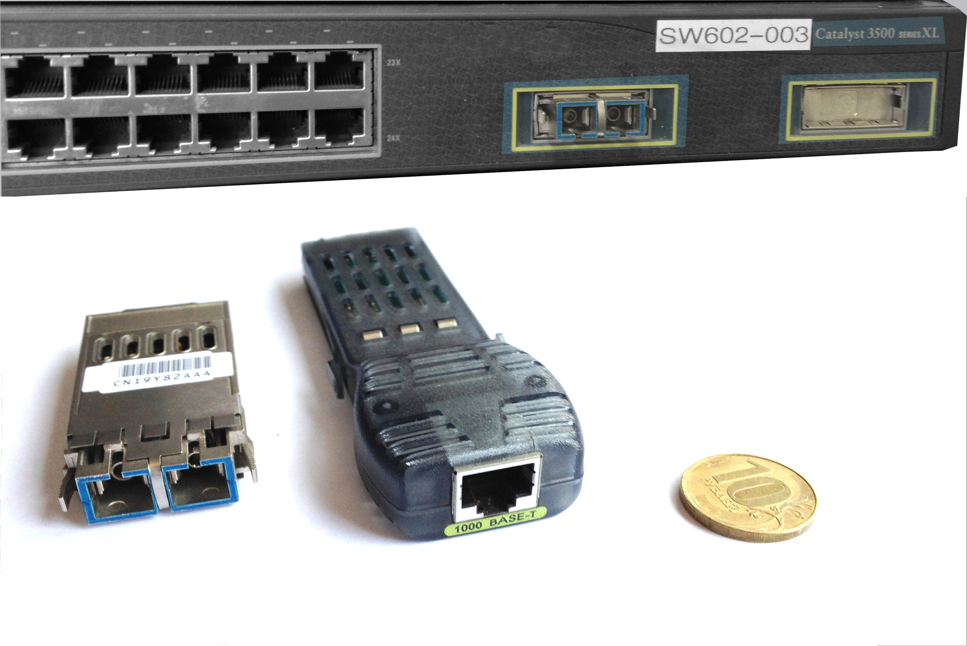
SFP
Small Form-factor Pluggable, successor to GBIC. Probably the most common format today, much more convenient due to its smaller size. This form factor has made it possible to significantly increase the density of ports on network equipment. Thanks to these dimensions, it became possible to implement up to 52 optical ports on one piece of hardware in one unit. Used to transfer data at speeds of 100Mbits, 1000Mbits. The image below shows a switch with optical ports and a pair of 1000Base-LX and 1000Base-T modules.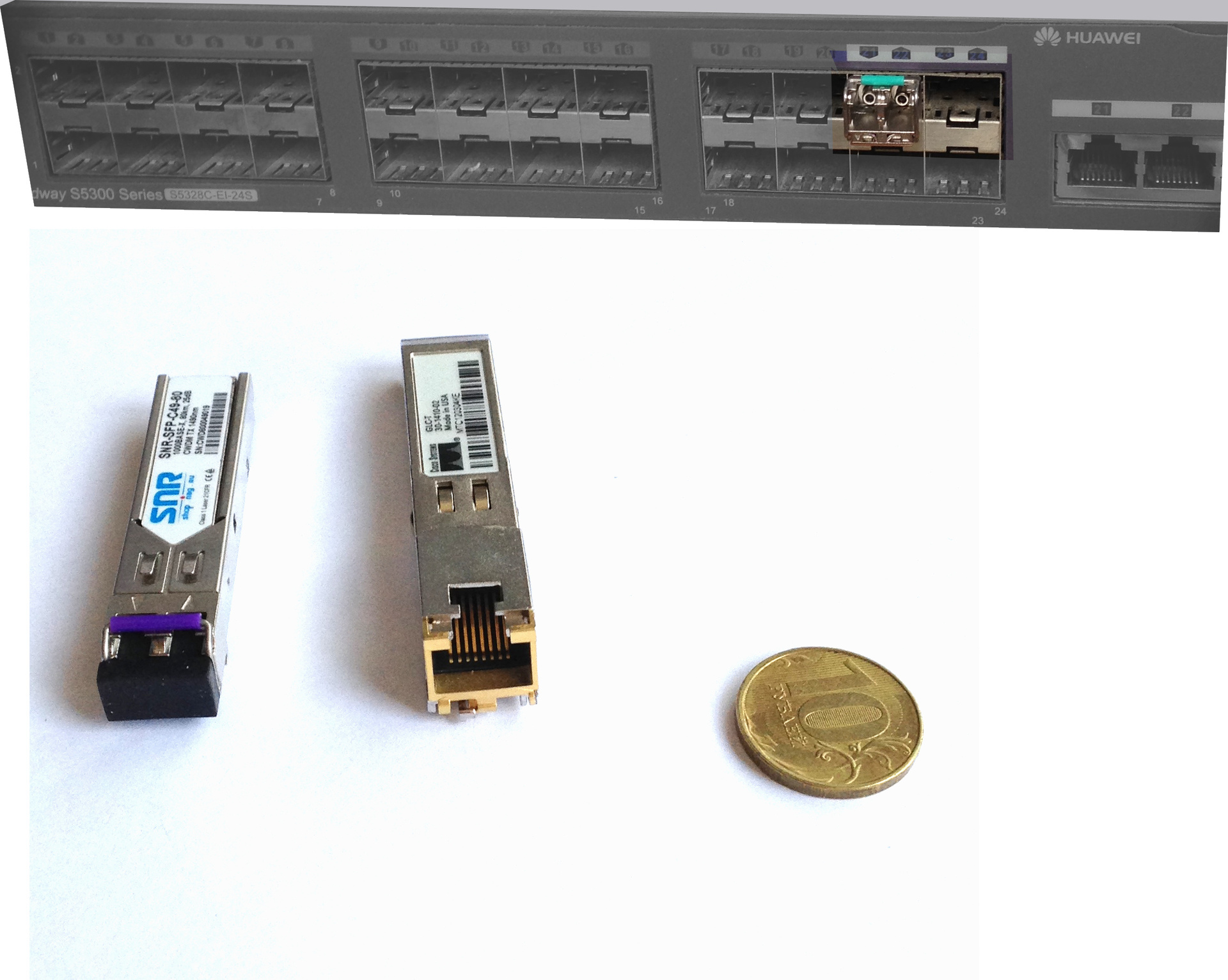
SFP+
Enhanced Small Form-factor Pluggable. They have identical SFP size. A similar size made it possible to make equipment with ports that support regular SFP and SFP+. Such ports can operate in 1000Base/10GBase modes. Only long-range CWDM modules are longer due to the heatsink. Used to transfer data at speeds of 10 Gbits. The small size added some special features - for long-range modules there are cases of too much heating. Therefore, there are no such modules for transmission over 80 km yet. In the picture below there are two SFP+ modules - CWDM and a regular 10GEBase-LR:
XFP
10 Gigabit Small Form Factor Pluggable. Just like SFP+, they are used to transfer data at speeds of 10 Gbits. But unlike the previous ones, it’s a little wider. The increased size made it possible to use them for shooting over longer distances compared to SFP+. Below is an additional board for Huawei with XFP installed and a couple of such modules.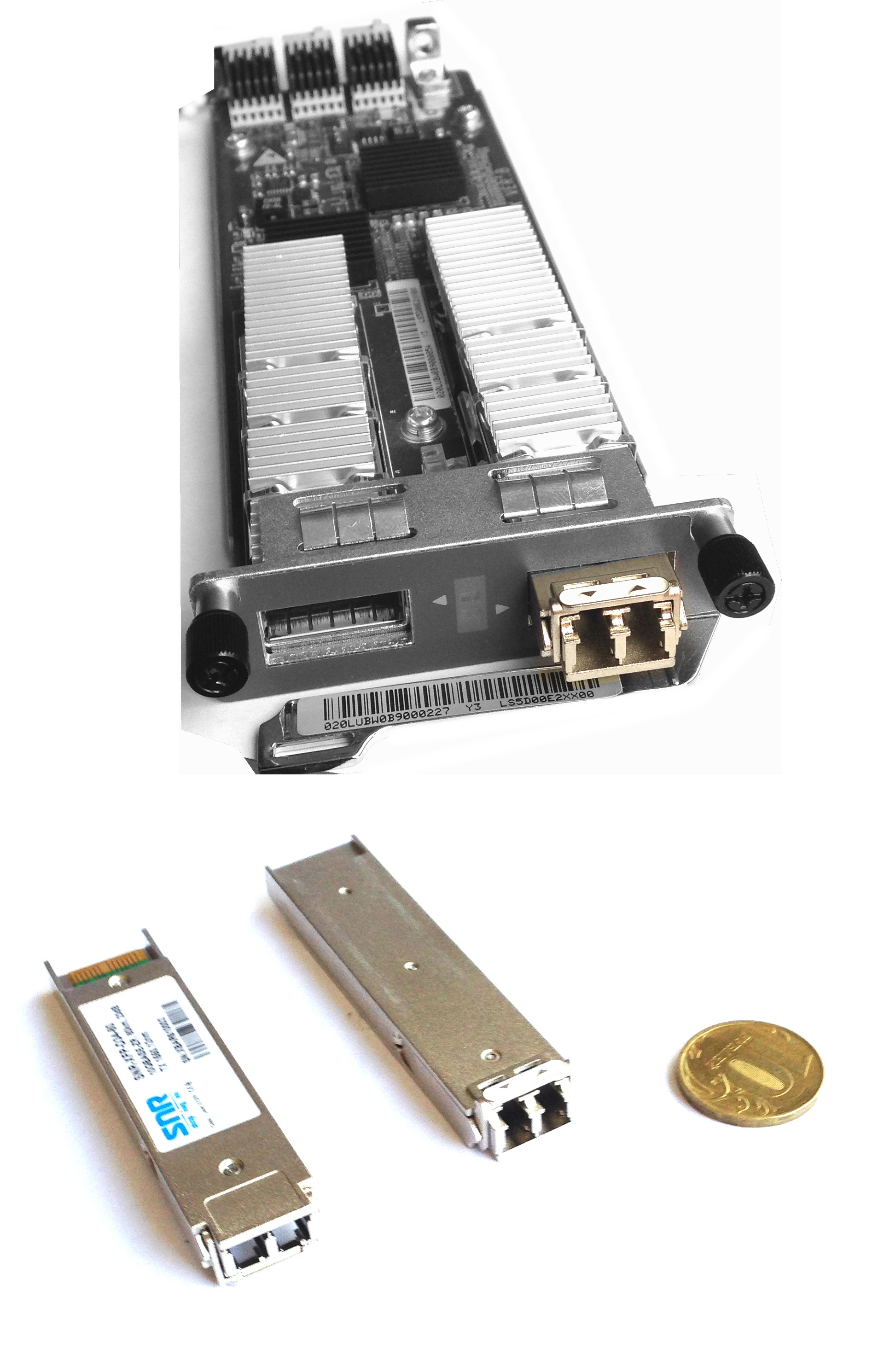
XENPAK
Modules used primarily in Cisco equipment. Used to transfer data at speeds of 10 Gbits. Nowadays you can rarely find use for them, and occasionally you can find them in older lines of routers. Such modules are also available for connecting 10GBase-CX4 copper wire. Unfortunately, I only had one XENPAK 10GEBase-LR module and an old Cisco board WS-X6704-10GE for them.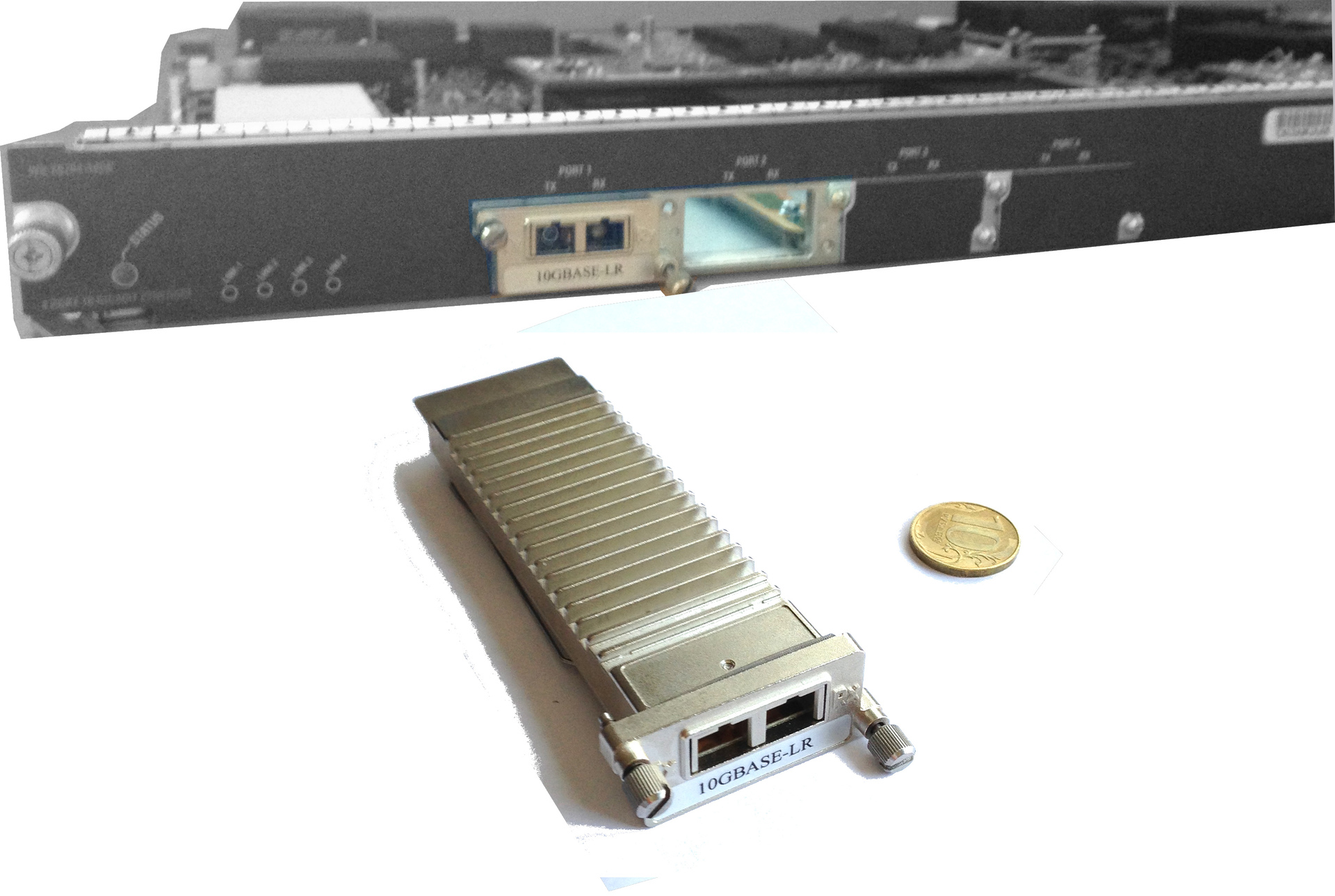
X2
Further development of XENPAK format modules. Often, a TwinGig module can be installed in the X2 connectors, into which two SFP modules can already be installed... This is necessary if the equipment does not have 1GE optical ports. Basically, the X2 form factor is used by Cisco. X2-SFP+ (XENPACK-to-SFP+) adapters are available for sale. It’s interesting that such a kit (adapter + SFP+ module) is cheaper than one X2 module.Unfortunately, I only had an adapter on hand, but to understand what these modules look like and what size they are, this is quite enough. The figure below shows the X2-SFP+ adapter with an inserted SFP+ module.

But if anyone is interested, here you can see more pictures and capabilities of this connector.
Yes, I did not touch on relatively new form factors (QSFP, QSFP+, CFP). At the moment they are not very common yet.
Various standards
As you know, the 802.3 committee has adopted many different Ethernet standards. Accordingly, optical modules support one of them. There is a good cheat sheet on Ethernet standards. The most common types now are:- 100Base-LX - 100 megabits over fiber over 10 km
- 100Base-T - 100 megabits over copper per 100 m
- 1000Base-LX - 1000 megabits over fiber over 10 km
- 1000Base-T - 1000 megabits over copper per 100 m
- 1000Base-ZX - 1000 megabits over single-mode fiber over 70 km
- 10GBase-LR - 10GE over 10 km single-mode fiber
- 10GBase-ER - 10GE over 40 km single-mode fiber
Using wavelength division multiplexing
The optical modules described above transmit a signal primarily at a wavelength of 1310 nm or 1550 nm on two fibers (one for transmission, the other for reception). They have a broadband photodetector (receive everything) and a laser emitting at a certain wavelength (roughly, of course). But it is possible to use wavelength multiplexing. This makes it possible to use fewer fibers to organize multiple channels, thereby increasing the throughput of a single fiber.WDM
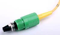
Such modules work in pairs; on one side, the signal is transmitted at a wavelength of 1310 nm, on the other, 1550 nm. This allows you to use one instead of two fibers to organize one channel. The receiver on such modules remains broadband. Available for both 1GE and 10GE. Below are photographs of a pair of WDM modules with different connectors for connecting LC and SC patch cords.
In most cases, it is preferable to use WDM modules for short distances. Their price is not very high (1 thousand rubles per module versus 500 rubles for a regular one). The reason is that you save a whole fiber, so you can then run another similar channel on it. Although of course there are other ways to save fiber.
CWDM
Further continuation of WDM technology. Using it, you can achieve up to 8 duplex channels over one fiber. For these purposes, CWDM multiplexers are used (passive devices with a prism inside, allowing the signal to be divided into colors with a step of 20 nm in the range from 1270 nm to 1610 nm). For this purpose, special CWDM modules are also used; in common parlance they are called “colored”; they transmit a signal at a certain wavelength. At the same time, the receiver on them is broadband. In addition, such optical modules are often made for transmission over long distances (up to 160 km). The figure below shows a small CWDM-SFP kit, on which, using multiplexers, you can raise 2GE on a single fiber.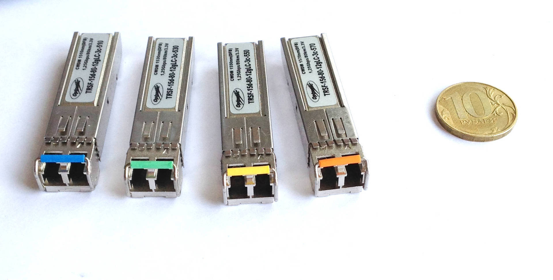
As you can see, everyone's bows are different. Depending on the wavelength, the module has its own coloring. Unfortunately, they are different for all manufacturers.
This is where the concept comes in optical budget. True, his calculation is beyond the scope of this article. In short, the more ports available, the more channels you can multiplex, the greater the attenuation will be. In addition, different wavelengths produce different attenuation per kilometer of transmitted signal. You also need to consider the type of fiber...
You can write a lot about methods for selecting such modules, about the intersection of wavelengths, about unwanted lengths, about ADD/DROP modules. But this is a separate topic.
Connectors
This is where you will connect the optical patch cord. Optical modules currently use mainly two types of connectors - SC and LC. Rough and slangy - large and small squares. It is clear that if you have a patch cord with an SC connector, you will not connect it to the LC connector. You need to either change the patch cord or install an adapter. In most cases, SFP modules have an LC connector, while X2/XENPAK has an SC connector. The images above already showed modules with various connectors.A little about patchcords
Optical patch cords, also known as optical cords. We will be interested in the following characteristics: duplex/simplex (number of fibers), polish (currently UPC blue or APC green), connector (SC, LC, FC), multimode and length. Of course, the thickness of the fiber core is also important, but now multimode conventional cords use a standard thickness. Below I have presented an image with different types of patchcord ends.

Basically you will come across the following designation for cords - ШО-2SM-SC/UPC-SC/UPC-3.0. This is deciphered as follows: Optical cord Duplex Single-Mode (Single-Mode) with SC connectors and UPC polishing on one side and SC-UPC on the other, 3.0 meters long. Accordingly, for example, ШО-SM-LC/APC-SC/APC-15.0- single-mode duplex cord with LC-LC connectors and APC engraving 15 meters long.
Some features
Optical modules are active equipment; they consume electricity and generate heat. This should be taken into account when connecting the equipment to the electrical network. Also, a switch filled to capacity with powerful modules may require additional cooling.Do not forget that lasers are built into optical modules, and some safety precautions must be observed with them. Of course, in most cases they do not pose any threat due to their low power, but there have been cases where long-range, powerful 10GE modules can completely burn out the retina of the eye or leave a burn if you use your finger as an attenuator.
Modern optical modules have the function DDM (Digital Diagnostics Monitoring)- they have a built-in number of sensors through which you can determine the current value of some parameters. This is viewed through the interface of the equipment in which the module is installed. The most important parameters for you are the current received power and temperature.
A number of network equipment manufacturers prohibit the use of third-party modules in their equipment. At least before Cisco did not allow them to be launched, they simply did not work in it. Now they are known in narrow circles
Flat connectors. RS series connectors. RS series connectors. Connectors of the SPC series (Super Physically Contact). UPC series connectors. APC series connectors. FC type connectors. Adapter for FC with attenuator. FC connector with metal ferrule. ST type connectors. SC type connectors. Biconic. DIN. D4. E-2000. LC type connectors. Connectors type MT-RJ. Connectors type VF-45. Connectors type MU. Prospects for local networks.
Optical connectors
Basic transmission parameters
Key Features optical connectors can be divided into the following groups: transmission parameters, long-term stability and resistance to external conditions.

The main transmission parameters of optical connectors are insertion attenuation and back reflection. These parameters depend mainly on factors such as the transverse displacement of the axes and the angle between them, as well as on the Fresnel reflection of the optical signal at the interface between two optical media.

Optical attenuation is of greatest importance for assessing the losses introduced by a detachable connection. This parameter has a major influence on the amount of total losses in the optical path. The amount of optical attenuation mainly depends on the misalignment (lateral deviation) of the cores of the optical fibers being joined.
In addition to the insertion attenuation, an important optical characteristics is the reverse reflection. The main source of the reflected signal is the interface between two media, for example, the material of an optical fiber and air. This component of losses can reach significant values. In addition, the back reflection is not constant over time. Under the influence of external influences, it can ultimately disrupt the stability of the system. Back reflection poses the most serious problems for narrow-band lasers with high radiation coherence (which, for example, are used in DWDM systems and in equipment for cable television networks).
Due to the small number of detachable connections in the path, the requirements for the amount of losses they introduce were somewhat reduced compared to the requirements for, for example, welded connections. This made it possible to significantly simplify the design and reduce the cost of products in which the positioning of the mating fibers is limited by passive transverse adjustment.
Termination technology
Manufacturers offer various termination technologies, that is, mounting connectors onto optical fibers.
At a certain stage (which can now be considered initial) it was assumed that the technology for creating detachable connections would include technological operations for securing the connected optical fibers in the plug-blank using a chemical fixative. Epoxy adhesive or its analogues was used as a fixative. Once secured, the fiber had to be cleaved and then the end of the connector with the protruding fiber had to be specially polished until the required end shape was achieved.
In order to speed up the installation process, technologies without the use of epoxy adhesive have been developed. Such technologies use mechanical fixation of the fiber with clamps built into the connector, thermal fixation with hot melt adhesives, etc. However, over time, the popularity of such technologies has decreased. Probably, the reasons for this were the cold flow of hot melt adhesives under pressure, as a result of which the optical fiber inside the connector shifted along the axis over time, and this entailed deterioration or loss of physical contact, and, consequently, an increase in insertion losses and back reflections.
Currently, the most widespread are connectors with a built-in piece of optical fiber in a buffer and secondary coating. This section is connected to the cable fiber. Despite the fact that instead of one joint there are two, this technology has proven itself well in practice. Its main advantage is the absence of the technological operation of polishing the end of the connector when terminating fibers, which requires a lot of time, and for high-speed networks, also expensive grinding and control equipment. These procedures are carried out in stationary conditions at the manufacturer. This approach allows the manufacturer to almost endlessly improve the quality of polishing the ends of the fibers being connected, use new technologies aimed at reducing losses and improving parameters optical connectors, without forcing the buyer to purchase more and more advanced (and, of course, expensive) equipment for final preparation of connectors for operation.
Ensuring optical contact
It is technologically difficult to achieve completely perpendicular ends with ideal contact surfaces during the fiber polishing process. Minimizing the magnitude of the reflected signal requires a guaranteed absence of an air gap between the cores of the joined optical fibers. To achieve this, the ends of the joining fibers are polished in such a way as to obtain spherical surfaces. When joining, longitudinal pressure of the fibers is set, which causes elastic deformation of the ends of the fibers and optical contact in the area of the cores of the fibers being connected, at which the air gap between them becomes minimal.
Flat connectors
One of the first solutions for preparing the end surfaces was to polish the end of the tip with the optical fiber fixed in it perpendicular to the fiber axis. To avoid direct contact of fibers, which can lead to serious damage - scratches and chips - with this approach, a recess of about several micrometers (2-3 microns) is created. To improve performance, an immersion gel is sometimes used, the refractive index of which is close to the optical fiber material. The gel fills the gap between the tips.
PC series connectors
A method of preparing end surfaces called “Physically Contact” (PC) involves fixing the optical fiber in an aluminum tip. The end is polished in a certain way in order to achieve full contact of the end surfaces. However, when polishing the fiber, negative changes occur in the surface end layer in the infrared range (the so-called “infrared layer”) due to mechanical changes during polishing. This factor limits the use of such connectors on high-speed networks (565 Mbit/s).
Connectors series SPC (Super Physically Contact)
To improve optical fiber contact, the core radius was narrowed to 20 mm, and softer zirconium was used as the tip material. This approach reduced polishing defects such as bevels. The ability to bend zirconium at the submicron level allowed the fiber to contact even at bevels of hundreds of microns without significant deterioration in parameters. However, such polishing leaves the problem of the infrared layer unresolved.
UPC series connectors
The UPC (Ultra Physically Contact) end polishing technique is characterized by low stress. Polishing is carried out under the control of complex and expensive control systems. As a result, the problem of the surface infrared layer is eliminated. The reflection parameter has been significantly improved, and such connectors can be used in high-speed systems with a throughput of 2.5 Gbit/s and higher.
APC series connectors
The most effective way to reduce the energy level of the reflected signal is the method of polishing the ends of optical fibers at an angle of 8-12° from the perpendicular to the fiber axis (Angled Physically Contact - APC). At such a junction, the reflected light signal propagates at an angle greater than the angle at which the signal is introduced into the optical fiber.
APC connectors are distinguished by the color coding of the shanks (usually green), since they cannot be used in conjunction with connectors of other polishes.
It should be noted that some manufacturers interchange the names of Super PC and Ultra PC, which should be taken into account in order to avoid connections that do not correspond to design parameters. This is especially true for newly installed adapters and connectors on lines where products from other manufacturers are already used.
In general, when connecting two connectors via an adapter, it is better to use connectors of the same series. When pairing connectors of different series (flat, super PC, ultra PC), the reflectance of the mixed pair will be worse. The use of other series in conjunction with the APC series is generally unacceptable and may lead to failure of one or both connectors.
Main types of connectors
FC type connectors
FC type connectors were developed by NTT and are primarily intended for use in single-mode long-distance communication lines, specialized systems and cable television networks. A ceramic tip with a diameter of 2.5 mm with a convex end surface with a diameter of 2 mm ensures physical contact of the abutting optical fibers. The tip is manufactured to strict geometric tolerances to ensure low loss and minimal back reflections. The tip radius ensures physical contact between the mating fibers.

To fix the FC connector to the socket, use a union nut with an M8x0.75 thread. In this design, the spring-loaded tip is not rigidly connected to the body and shank, which complicates and increases the cost of the connector, but this addition pays off in increased reliability.

FC type connectors are resistant to vibration and shock, which allows them to be used on appropriate networks, for example, directly on moving objects, as well as on structures located near railways.
ST type connectors
BT connectors were developed by AT&T specialists in the mid-80s. The successful design of these connectors has led to the appearance on the market of a large number of their analogues.
Currently, ST connectors are widely used in optical subsystems of local networks.

A ceramic tip with a diameter of 2.5 mm, with a convex end surface with a diameter of 2 mm, ensures physical contact of the joined optical fibers. To protect the fiber end from damage when twisting during installation, a side key is used that fits into the groove of the socket; The plug on the socket is fixed with a bayonet lock.
ST connectors are simple and reliable in operation, easy to install, and relatively inexpensive. However, the simplicity of the design also has negative sides: these connectors are sensitive to sudden forces applied to the cable, as well as to significant vibration and shock loads, because the tip is a single unit with the body and shank. This drawback limits the use of this type of connectors on moving objects.
ST connector parts are usually made of nickel-plated zinc alloy, less often of plastic.
When assembling the connectors, the aramid threads of the cable's reinforcing braid are laid on the surface of the rear part of the housing, after which the metal sleeve is pushed over and crimped. This design significantly reduces the likelihood of fiber breakage when the connector is pulled out. To further increase the mechanical strength of connecting cords, connectors from a number of manufacturers provide for crimping on the back of the housing not only the aramid threads, but also the outer shell of the minicable.
The active use of ST connectors has led to a search for options to improve the quality indicators of these products. Thus, as development progressed, SPS and UPS versions of connectors of this type appeared.
SC type connectors
One of the disadvantages of FC and ST connectors is the need for rotational movement when connecting to the adapter. To eliminate this drawback, which prevents an increase in the installation density on the front panel, SC type connectors have been developed. The SC connector body is rectangular in cross section. The tip is not rigidly connected to the body and shank.
The SC connector is connected and disconnected linearly (push-pull), which prevents the connector tips from rotating relative to each other when they are fixed in the adapter. The locking mechanism opens only when the connector is pulled out by the housing. The disadvantages of SC connectors include a slightly higher price and lower mechanical strength compared to the previously discussed connectors of the FC and ST types. The force pulling the SC connector out of the adapter is regulated within 40 N, while for the FC series this value can practically be equal to the strength of the minicable. As with ST connectors, this drawback limits the use of SC connectors on moving objects.
Biconic
Biconic connectors have become widespread in the United States thanks to the efforts of Lucent Technologies. The connector body is made of plastic and may contain a key that prevents the rotational movement of the core when screwed in. The non-standard spring-loaded ceramic core is made in the shape of a truncated cone, and at the base the diameter of the cone is almost equal to the internal diameter of the body. This design appears to be more reliable than its counterparts. However, studies have shown that this type of connector is inferior in temperature stability to connectors with a complex multilayer ferrule design. In addition, the non-standard core design made it difficult to use such connectors in hybrid connectors.
Currently, Biconic connectors have completely lost their position to modern types of connectors with standard core sizes.
DIN
Traditionally, products meeting this standard have been widely distributed in Germany and other European countries. The standard 2.5mm diameter ceramic core protrudes well beyond the body. The plastic case is equipped with a key that prevents the core from rotating around its axis when screwed into the adapter.
DIN connectors are used in test equipment and telecommunications equipment.
D4
D4 connectors have also become widespread in Europe. The main features of their design are a key that protrudes beyond the metal body (low-tech design) and a non-standard ceramic core with a diameter of 2 mm. For fixation on the socket, the connectors are equipped with a union nut with an M8x0.75 thread.
Despite these disadvantages, this type of connector was produced for quite a long time, and by the end of the 90s of the last century, PS, SPS and UPS versions of such connectors were already being produced. The main manufacturers of D4 connectors are Western European companies, however, for the production of equipment supplied to European operators, the production of such connectors has also been established in the USA.
E-2000
E-2000 connectors feature one of the most complex designs. The connector is connected and disconnected linearly (push-pull). The locking mechanism opens only when the connector is pulled out by the body using a special key insert. Accidentally turning off such a connector without using a key is almost impossible (that is, a load is required to destroy the latch of the connector body).

The tip in E-2000 type connectors is made in the form of a multilayer ferrule with a diameter of 2.5 mm. The housings of connectors and adapters are made of durable polymer. The main innovation is plastic curtains that act as plugs when the adapter is disconnected. They also serve to prevent dust from entering the optical contact plane.
This type of connector is characterized by improved optical performance and stable temperature characteristics, as well as high reliability (at least 2 thousand on-off cycles are guaranteed). The cross-section of the housing is square, which makes it easy to implement duplex connectors.
Among other things, it should be noted that the undeniable advantage of these products is the reduction of the influence of the human factor. When turned on, the following are warned: the possibility of damage to the end surface of the optical fiber due to excessive forces aimed at connecting two connectors; insufficient activation force; incorrect positioning, as well as flaws when cleaning optical contact surfaces.
The connector is designed and manufactured by Diamond, which pays special attention to product quality. In addition to Western European countries, the production facilities of this company are also located in Eastern European countries. Despite the high optical performance and reliability of the design, the price factor still holds back the large-scale implementation of the E-2000.
The appearance of the E-2000 marked the beginning of a new stage in the creation of connectors for optical fibers - the development of SFF (Small Form Factor) connectors, which will be discussed further.
High Density Connectors
An analysis of the advantages and disadvantages of previously developed connectors showed the need to create new types of connectors. With the same operating parameters as their predecessors, they had to provide greater space savings to increase the density of mounting on the faceplates.
The dimensions of the connector for metal current-carrying conductors of the RJ-45 type were taken as the basis for the dimensions of the adapters. This made it possible to use common design solutions for the installation of RJ-45 and optical connectors of the designs being developed.
Leading manufacturers of passive optical components have become involved in the development of new generation connectors. Of the whole list of models, the most widely used connectors are LC, MT-RJ, VF-45n MU. A number of manufacturers of passive optical components have already acquired licenses to produce these types of connectors, and their sales volumes are constantly growing.
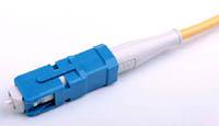
LC type connectors
The developer of LC type connectors, the American company Lucent Technologies, is one of the leading manufacturers of telecommunications equipment, and therefore a “trendsetter” in the field of passive optics. This type of connector was initially (and, as it later turned out, quite rightly) assigned the role of a sales leader both in the United States and in Europe.
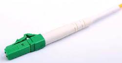
The design of the connector is relatively simple: a ceramic core with a diameter of 1.25 mm, not connected to a plastic housing. The fixation mechanism is a latch (similar to RJ-45). The losses, according to the manufacturer, are about 0.2 dB. A pair of connectors can easily be combined into a duplex.
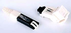
Connectors type MT-RJ
MT-RJ connectors were developed by a consortium of manufacturers including AMp Hewlett-Packard, Siecor LIN, Fujikura and USConnec. These connectors are manufactured exclusively in the form of duplex pairs and therefore cannot be considered universal. Technologically, they are difficult to produce.
The connector body contains a pair of metal guides into which two optical fibers are pre-installed. The optical fibers of the cable are welded to the pre-installed fibers. After installation, the cable is secured by turning the locking key.
The average loss is about 0.2 dB.
MT-RJ connectors are used in switches, hubs and routers by many leading equipment manufacturers.
Connectors type VF-45
3M Corporation also could not help but respond to market trends regarding the introduction of SFF connectors. The company developed its own design - the VF-45 duplex connector for single-mode and multimode fibers - and began to actively promote it on the market. It may also be sold under the name SJ.
This connector is made using push-pull technology - the connection is made linearly. It should be noted that for ergonomic purposes, the connector shank is inclined at an angle of approximately 45° from the plane of the fiber connection, that is, it is lowered down. This ensures high installation density - an RG-45 mounting panel is used. Instead of the ceramic ferrules used by most manufacturers, a V-shaped groove is used, which makes the connector cheaper to manufacture.
The manufacturer guarantees the quality and stability of characteristics, based on more than ten years of experience in operating optical connectors made using this technology. The connector is equipped with a self-latching shutter to prevent dust from entering the optical contact surface.
The manufacturer guarantees high quality indicators: the attenuation level is not higher than 0.75 dB, and the back reflection is less than 26 dB.
Like MT-RJ type connectors, VF-45 are intended for use in telecommunications equipment: switches, hubs, routers.
MU type connectors
This type of connector was developed by NTT and is manufactured by a number of other companies. They are an analogue of SC, approximately halved. Due to the reduced dimensions in connectors of this type, the fixation mechanism may be less reliable.
The tip and centralizer are ceramic, with a diameter of 1.25 mm. The body is made of plastic, parts are made of polymer and metal.
The share of equipment produced with MU type connectors is relatively small, but there are growth prospects, primarily due to a decrease in the share of use of connectors of earlier designs in equipment.
It is assumed that the new generation of connectors will gradually take a leading position in the market, and then completely displace their predecessors, if by this time more advanced connector designs have not been developed that combine the advantages of the above models and, at the same time, surpass them in some respects. or factors (for example, price or reliability).
Prospects for local networks
Today, the active use of single-mode optical fibers in the construction of local networks determines the need to produce many connectors in both single-mode and multimode versions.
Further improvement of structured cabling networks is possible using materials that are not currently used (for example, polyamide fibers as a transmission medium). This will determine the need to develop specialized passive optical components, which will highlight solutions for local networks as a separate independent area. As a result, it will be impossible to use existing designs of passive optical components (in this case, optical connectors) as universal ones. At the same time, the emergence of new design solutions can become a powerful impetus both for the modification of existing ones and for the creation of specialized new types of connectors.
Another driving factor for connector improvements is the development of higher-speed transmission system equipment. The consequence of this will be new requirements for passive optical components, which also necessitates the improvement of existing and the creation of new designs of optical connectors.
The increase in the number of operated ports, speeds and range of information transmission requires new approaches to organizing the connection of equipment ports and SCS. One approach is to use LC connectors, which are available in a variety of designs. However, not all of them are effective in conditions high density installation of passive and active ports.
LC connector
The optical interface type LC (Lucent Connector) is one of the most widely used types of plug-in connectors today. The connector was introduced to the market in 1996 by Lucent Technologies and received recognition from experts due to a number of advantages that the user receives in real operating conditions of the final passive and active equipment along with the use of SFP transceivers. Analysts estimate that today more than 60 million LC connectors are installed worldwide. Currently, about 30 companies officially have a license to produce this type of interface.
Among the main advantages of the LC optical connector is the ability to place a duplex optical port in the same area as a copper RJ45 port (Figure 1), and the LC connector uses a similar latch mechanism.
In the original design, the LC optical socket had mounting dimensions equal to the dimensions of the hole for the copper socket, which allowed for the “reuse” of existing copper patch panels and their combination.
 |
 |
 |
 |
 |
 |
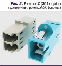
The limited available space in data center computer rooms and the general increase in the number of active equipment units per unit of room area have led to the emergence of more efficient active equipment - in terms of size, power consumption and cooling. In turn, this has forced structured cabling manufacturers to adapt their solutions to accommodate more passive optical ports through the introduction of a new small-sized duplex LC socket (the so-called SC foot print type), the mounting dimensions of which coincide with the dimensions of a standard simplex SC socket (Fig. 2). ).
Density or comfort
The advent of a small-sized duplex LC socket made it possible to increase installation density due to a closer arrangement of ports on the optical patch panel. Today, one standard height unit can accommodate up to 48 LC duplex receptacles. From the point of view of the data center infrastructure, this means, for example, the ability to significantly reduce the number of units used in a rack with active equipment and make the switching field more compact. However, from an operational point of view, the issue of ease of maintenance of plug-in LC optical connectors remains unresolved. This is where most SCS manufacturers have failed to make significant technological progress.
The ease of use of any detachable connection generally implies that you can get free access to the optical connector without affecting adjacent, already connected connectors. This problem is especially critical in conditions of high installation density, which is typical today for central switching optical distributions, as well as when connecting a number of types of network switches or routers.
It is no secret that just a few years ago, operation department specialists perceived the LC interface extremely negatively, citing the fact that it is extremely small in size compared to the usual SC connector, and that it is difficult to remove from the socket (often SCS manufacturers even suggested using a special tool, facilitating this operation) that a “beard” is formed from mixed up patch cords, since the latches of the connectors constantly cling to the cable, complicating the process of removing the optical cord.
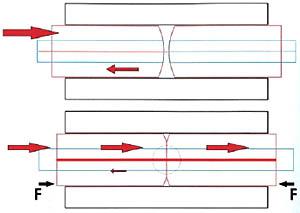
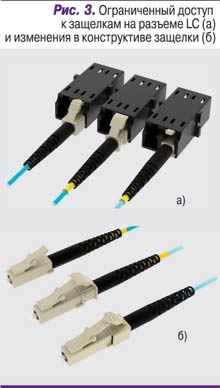
Since the density of connections in the case of LC is two or more times higher compared to other connectors (for example, SC), and the design of the latch of the LC connector and the copper RJ45 connector is implemented in a similar way, then in conditions of connected cords, access to the latches is significantly limited (Fig. 3, a). I think most specialists well remember the best tool for servicing duplex LC connections - ordinary tweezers.
Developers and manufacturers of LC optical connectors, taking this limitation into account, made design changes to the shape of the latch (Fig. 3, b). Various design options offered by different manufacturers suggest, for example, creating an additional platform for pressing the connector latch (the platform is part of either the connector body or a duplex clip), increasing the useful working area of the latch, or complicating the geometry of its surface so that pressing the connector latch is triggered more effective.
The presence of an additional platform simplifies access to the connector latches and reduces tangling of optical cords. On the other hand, due to the deformation characteristics of the polymer material and the small size of the latch, it is impossible to ensure uniform pressure on the latch in the duplex version of the LC connector. This usually causes the duplex connector to stick when unplugged, with one latch engaging but the other not. Along with additional time and effort, this can lead to destruction of the connector housing due to asymmetrical side loading.
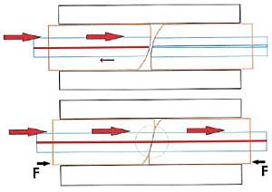
Among the interesting, non-standard solutions available on the market, it is worth noting the design of the LC connector with the so-called reverse latch (Fig. 4). Keeping full compatibility with standard sockets, this connector design provides good access to the latches due to the enlarged area, and reduces the likelihood of optical cords being tangled due to the optical cord cable getting caught on the latch. In addition, in the duplex version, due to the design of the clip used, the applied force is evenly distributed across both latches.
Flexible shanks
One of the alternative approaches that increases the ease of maintenance of LC detachable connections in high-density installation conditions is the use of shortened flexible shanks (Fig. 5). Manufacturers offering these solutions report that optical ports are easily accessible and that patch cords can be safely routed even when there is limited space between the equipment mounting plane and the cabinet door.
Note, however, that the use of a shortened connector body and/or a flexible shank nevertheless does not solve the issue of ease of access to the latches of the connector itself.
LC-HD design
From the point of view of the operation of detachable connections, it is of particular interest to be able to combine the high connection density characteristic of the LC interface with the push-pull fixation option of the SC interface. In this case, access to the connector latches, especially in the duplex version, is not required at all. Such a design is presented on the market today (Fig. 6) under the trademark LC-HD (the subject of an active patent), where the abbreviation HD stands for High Density.
The manufacturer, while maintaining full compatibility with standard LC sockets and SFP/SFP+ transceivers, has created a solution for organizing high-density connections both on patch panels and on cards/blades of active equipment. Its main feature is the use of a special clip, thanks to which there is no need to access the connector latches at all.
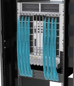
The proposed design solution works equally effectively in cases of horizontal and vertical orientation of LC sockets or optical transceivers, for example, on the blades of a heavy multiport switch (Fig. 7).
By applying an even and symmetrical force to the connector latches, the user can connect or disconnect a duplex connector from the switch port almost blindly - this is a typical situation, for example, when using ultra-tight transceiver blades.
A little about the prospects
And in conclusion, I would like to draw attention to a special type of optical duplex interface - mini-LC. This solution arose as a consequence of an attempt to increase the density of transceivers on the switch blade. Its characteristic feature is the reduced distance between the geometric centers of the connectors - 5.25 mm instead of 6.25 mm for the standard version. Corresponding changes were made to the design of the transceivers, which were called mini-SFP.
Apparently, the practical future of such a solution is not yet obvious, although a number of manufacturers of optical connectors have announced the availability of mini-LC connectors and patch cords based on them. In any case, this solution cannot be adapted within the framework of a complete cabling system, since the requirement of compatibility and universality of cabling in relation to active equipment of various vendors in the data center computer room is not met.
In general, developers and manufacturers passive components are only at the very beginning of their journey, and of course, new interesting engineering solutions will still be presented to the market.

