Star news


Frequency characteristics of passive components. Blog › The influence of cables on speaker parameters
For correct operation of the designed device, careful selection of passive components is necessary. It is necessary to consider in detail the characteristics of the passive element base of the future device and the preliminary layout of the housings on the board.
Often, developers do not attach much importance to the operating frequency range of passive components when selecting the element base for a future device. This leads to unpredictable results. I would like to point out that this does not only apply to high-frequency analog devices, since RF signals have a strong effect on passive low-frequency components through galvanic coupling or radiation. For example, a simple active low-pass filter on an op-amp can act as a high-pass filter when exposed to high frequency at its input.
Therefore, for optimization studies and retraining of power transmission lines, it is necessary to give priority attention to changes in linear geometry, in particular, the approximation of external phases and increasing the distance in bundles of external phases to the detriment of the replacement of phase conductors.
The sensitivity analysis allowed us to deepen our knowledge of the calculation of electrical parameters and the influence of the physical characteristics of the line on these parameters. The observations made will support the work related to modeling and its applications in transmission line optimization.
Resistors
At high frequencies, a resistor has its own inductance, capacitance and resistance. See fig. 5.
Resistors can be divided into three main types: wirewound, carbon composite and film. The structure of a wirewound resistor is a coil of high-resistance metal, which is where its own inductance comes from. Film capacitors have a similar structure, so film capacitors also have inductance. The inductive properties of film resistors are less pronounced than those of wire resistors. Film resistors with a nominal value of up to 2 kOhm can be safely used in RF circuits.
Wave propagation in overhead wires with ground return. Accurate modeling of frequency-dependent transmission lines in electromagnetic transient simulations. Sensitivity analysis of electrical parameters of transmission lines in the frequency domain. Accurate representation of soil behavior for transient studies, accurate representation of soil behavior for transient studies.
Multiphase transmission line model using short-range modes. They are manufactured with iron powder cores with different base material depending on the required operating frequency. The high section of the magnetic core, obtained due to the anisotropic characteristics of the material, allows for high inductance values with high saturation current. The ideal application for these inductors is as an output filter for sine wave generators, current generators or electric motor drives.
Since the leads of the resistors are parallel to each other, therefore, there is a significant capacitive coupling between them. The larger the resistor value, the smaller the inter-pin capacitance.
Capacitors
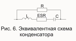
The equivalent circuit of a capacitor in the high frequency region is shown in Fig. 6.
They can operate from mains frequencies up to 100 kHz, depending on the ripple current to which they are exposed. Typically, solid copper conductors with a round or rectangular cross-section are used. When the ripple current to which the inductance is exposed is too high or too high a frequency, iron powder is no longer used. In inductors with a ferrite core, special design solutions are adopted to avoid overheating of the windings due to the “kink” phenomenon, that is, the dispersion of the magnetic flux that occurs at the height of the air gap.
Capacitors are used in circuit design as decoupling and filtering elements. To calculate the reactance of a capacitor, we turn to the following formula: 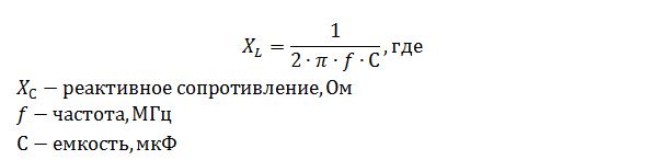
Based on the above formula, we calculate the reactance of a capacitor with a capacity of 10 μF at frequencies of 10 kHz and 100 MHz. The calculated values were 1.6 ohms at 10 kHz and 160 μohms at 100 MHz. Now let’s check if this is actually true.
Inductors in traditional or special layers
The high saturation inductance of this material, together with the small losses due to parasitic effects that can be achieved with very thin laminations, makes it possible to realize with these inductor cores a wide variety of applications: from levelers to levelers to current generators operating at low frequencies, with output filters to sinusoidal generators, with input filters for harmonic recovery in a three-phase converter. The “hanging” phenomenon requires special care when making windings and in the location of the air gap.
All the resistances mentioned add up to create an equivalent series resistance (ESR). Based on the above, we note that capacitors used in decoupling circuits must have low ESR. This is because series resistance limits the effectiveness of ripple and noise suppression. An increase in the operating temperature of the device also significantly affects the change in ESR and increases. Therefore, when using an aluminum electrolytic capacitor at elevated operating temperatures, it is necessary to use the appropriate type of capacitor.
For this type of product, the coast wrapping technique is used. In this way, the space between turn and turn is constant, ensuring optimal ventilation of the entire conductor, as well as optimizing the execution space. Using this method on cylindrical cores with various materials, we obtain very compact inductances, high currents and even more high currents saturation. The particular helical shape of the winding reduces the influence of stray currents, making them suitable for high frequency use.
When using electrolytic capacitors, you should carefully position and connect the capacitor on the board. The positive plate must be connected to the positive, the lines connecting the capacitor must be as short as possible. If the capacitor is connected incorrectly, currents begin to flow through the electrolyte with rapid failure of the capacitor itself.
The same fin winding technique is also used to make inductors, both in air and on a magnetic core, where the winding is made using a hollow copper tube to which a flow of coolant is applied. They are a very specific inductor, usually made to a specific customer design, and are used when the large power dissipated by the inductance cannot be dissipated locally, but must be removed elsewhere via a cooling unit or chiller.
The flow includes the outer part of the wire and the inner part. Thus, the self-induction coefficient is the sum of two terms. Given the unit length, we have the following expressions. Considering conductors in air and moving to decimal logarithms, the coefficient of self-inductance per unit length of conductor is then given by
There are also devices in which the direct current potential difference between two points can change its sign. In such cases, non-polar electrolytic capacitors are used.
Inductance
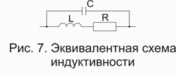
The equivalent inductance circuit in the high frequency region is shown in Fig. 7.
Inductance reactance is described by the following formula:
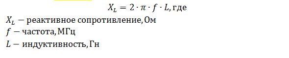
From the formula it can be seen that an inductance with a nominal value of 10 mH will have a reactance of 628 ohms at a frequency of 10 kHz, at a frequency of 100 MHz the calculated value will be 6.28 MOhm.
Printed circuit board
The printed circuit board also has all the described properties of passive components, but these properties are not so pronounced.
Printed conductors on a printed circuit board can be both sources of interference and receivers (antenna). Proper PCB routing minimizes radiated and inductive interference. Since any conductor on a printed circuit board can be considered an antenna, let's turn to the basics of antenna theory.
Basic Antenna Theory
One of the main types of antennas is a “pin” or in our case, a straight conductor. The total impedance of a straight conductor has resistive (active) and inductive (reactive) components:
![]()
On DC and at low frequencies the active component predominates. As the frequency increases, the reactive component becomes more significant.
The formula for calculating the inductance of a PCB conductor is as follows:
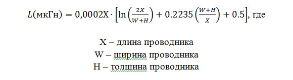
On average, printed conductors on a board have an inductance of 6...12 nH per centimeter of length. For example, a conductor 10 cm long has a resistance of 57 MΩ and an inductance of 8 nH per centimeter. At 10 kHz the reactance becomes 50 MΩ, and at higher frequencies the conductor must be treated as an inductance rather than a resistive conductor.
A whip antenna begins to function at a wavelength to antenna length ratio of 1/20. Therefore, a 10-centimeter conductor will serve as a good antenna at frequencies above 150 MHz. Returning to printed circuit boards, I note that, for example, a clock signal generator may not have a frequency of 150 MHz, but higher harmonics from the clock generator can become a source of high frequencies.
Another one of the main types of antennas is the loop antenna. The inductance of a straight conductor increases significantly when bending. An increased value of conductor inductance reduces the frequency at which the “antenna” sensitivity is maximum.
Experienced PCB designers who understand the effect of loop antennas note that the topology should not be designed in such a way that a loop is formed for critical signals. Otherwise, loops of forward and reverse current conductors are formed. See Figure 8. The figure also shows the effect of a slot antenna.
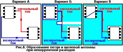
Take a closer look at the three options of Figure 8.
Option A: The most unfortunate of those presented. It does not use ground polygons. The loop circuit is formed by ground and signal conductors. It should be remembered that with a wavelength to conductor ratio of 1/20, a loop antenna is quite effective.
Option B: Compared to option A, this option is better. But here you can see a gap in the earthen testing area. The paths of forward and return currents form a slot antenna.
Option B: This option is the best. The paths of the signal and return currents coincide, thus the efficiency of the loop antenna is negligible. It is worth noting that this version also has cutouts around the microcircuits, but they are separated from the return current path.
The theory of reflections and matching of conductors is identical to that considered in the theory of antennas.
When the printed conductor is rotated at an angle of 90°, signal reflection may occur. This occurs due to a change in the width of the conductor. At the corner of the conductor, the width of the trace increases by 1.414 times, which leads to mismatch of the communication line, distributed capacitance and inductance of the trace. Modern automatic design systems offer different kinds smoothing corners, see fig. 9.
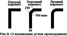
The best of the presented rotation options is the third option, since the width of its conductor is unchanged.
The calculations presented in this article clearly show that the influence of cables on the transmission of signals in the frequency spectrum audible to the human ear is negligible. It makes no sense to even think about capacitances, inductances and cable lengths;
Cables, like people, are now of two types during a crisis: working and non-working. :) Undoubtedly, they do not add any “color”, “mood” and other things that sellers or audiophiles love to talk about.
In addition to active resistance, which decreases with increasing cross-section, the cable is also characterized by inductive reactance, which increases with increasing cross-section. Yes, a large cross-section and low active resistance contribute to improved transmission at low frequencies, because reduce the damping coefficient. But increasing inductance degrades transmission at high frequencies. The RF roll-off can be calculated in the same way as the active resistance and can reach several dB at 10 kHz in real cables. Both poor damping and blockage can be clearly noticeable by ear. Moreover, the linear inductance of a flat pair increases both due to an increase in diameter and due to an increase in the distance between the conductors. Therefore, “thick” insulation cannot bring anything good but harm. The insulation is needed as thin as possible. This is an important difference between sound and power cable. It is not for nothing that the audio cable has insulation designed for only 50V and this is indicated in the passport. Single wires have the highest inductance (this happens in life), the least is coaxial. A good audio coax has excellent RF transmission.
Since the audio cable operates in a wide range of frequencies, the requirements placed on it are contradictory. On the one hand, it must have a large cross-section for high damping, on the other, a small cross-section for low inductance and good RF transmission.
Because The cable load impedance (loudspeaker impedance) has a complex dependence on frequency; in each specific case there is an optimum for the cable cross-section/shape. It is impossible to predict it in advance, because... It is impossible to say how much damping can be sacrificed for the sake of good HF transmission. Each individual, according to his taste, may have his own preferred ratio. Therefore, IMHO, to a large extent, selecting the optimal cable is black magic, which scammers readily exploit.
The above did not mean the use of a deliberately “wrong” cable, the parameters of which are completely unacceptable (most often too long and/or thin...) - this is not a matter of educational training.
In general, an ordinary multi-core acoustic cable with a core diameter of 2.5 square meters is more than sufficient. mm.

