Star news


Adjustable power supplies from 0 to 30 volts. Blog › DIY laboratory power supply
A power supply of 30 Volts and 5 Amps is widely used by radio amateurs in a variety of circuits. Various types of circuits for such devices have been published in the literature for radio amateurs; it does not require the use of special microcircuits and imported parts. Today, when purchasing such microcircuits, problems arise; in some areas, finding them is quite problematic. The block uses parts available to most people.
Main characteristics of the power supply:
- output voltage is adjustable in the range from 0 to 30 Volts;
- maximum current consumption at the output is 5 Amperes;
- The voltage drop at a current from 1 Ampere to 6 Ampere is very small and is not particularly reflected in the output parameters.
Power supply diagram.
The circuit of our power supply can be divided into 3 main nodes:
- internal power supply;
- protection unit against possible overloads;
- main node.
Main node is a voltage stabilizer that makes it possible to adjust signal parameters. It includes a differential stage, two amplification stages, and a regulator.
Internal network node- made according to the classical circuit with a transformer, diode bridge VD1-VD4, capacitors C1 - C7, and stabilizers DA1 and DA2
Protection node does not have any special features. The current sensor is selected for a current of three amperes, but can be increased to five amperes. For a long period of time it was used with a current of five amperes. There were no problems with this.
All nodes are connected according to the Darlington scheme.
The resistor for tripping the protection is selected according to needs. The 30V 5A power supply, with high-quality assembly and serviceable parts, can be used immediately after connecting to the network. Its adjustment consists of setting the required limits for changes in output voltage and current for the protection to operate.
The digital panel includes an input voltage and current divider based on the KR572PV2A microcircuit and four seven-segment LED indicators. The microcircuit is a highly sensitive converter up to three and a half decimal places, it works with serial counting with double integration, zero correction is carried out automatically, checking the polarity of the input signal.
For a clearer indication of signal parameters, a circuit on the KR572PV6 board is used. The dimensions of such a board are eighty by fifty millimeters. The voltage and current contact pads of the digital panel board are connected using flexible conductors to the contacts of the corresponding indicators. The KR572PV2A circuit is often replaced with the imported ICL7107CPL circuit, since its parameters and quality are superior to the standard one.
The regulated power supply 1501 (15 volts, 1 ampere) was no longer enough for my needs, it was decided to buy something like YaXun PS-1502DD+ (price from Ali around 3500 rubles) 2 amperes should, in theory, be enough.
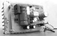
But then the following power supply came into my hands:
Anticipating "why not remake the power supply from the computer to suit your needs, a lot of watts, a lot of amps and a lot of voltage"? The fact is that sometimes I assemble low-power amplifiers (powered by 12 V) and listen to the background pulse block I don’t really want food. And assembling with your own hands - well, this is a long song, and now I don’t have time for it. For these reasons, I set out to assemble a simple power supply with the following characteristics:
-output voltage up to 12-15 Volts (for the most part, this voltage is enough for me);
-current supplied to the load is at least 3-5 Amperes (but the transformer of this unit allows it to output a nominal 10 Amperes);
-small number of pulsations;
- digital indication of voltage and current;
- current and voltage regulation;
Block face:
At the bottom there are two holes left over from the sockets, the body is aluminum. Instead of one socket, a button fits well. There are 4 screw holes around - it was decided to insert LEDs into them to indicate the operation of the unit.
Previously, I ordered this block from Ali:
Assembled on an stm microcontroller, I was captivated by its price and capabilities.
It fits the voltage error quite accurately; to be honest, the ammeter was disappointing. The website states an error of 0.01 A (10 mA), as a result, at zero positions of the knobs, the consumption is 50 mA (this is the short circuit current and the readings of the standard tester), but this ammeter does not show anything at all.
When the current reaches 100 mA (standard tester), the readings on this ammeter are ~70-80 mA, then we give 150 mA, - the error is within 10 mA (between the standard tester and this unit) and up to 1 Ampere more or less accurate (difference 10- 20 mA). Then it lies within 50-100 mA. Here it clearly does not fit into the 1% error on readings up to 100 mA. Suitable for home use.
Next, I decided on the placement of the power supply unit on the muzzle.
Block connection diagram:
I messed up the paint a little, but God bless it, I’ll repaint the face black. It was decided to leave the mains fuse; in my opinion, it fits well into the interior and will perform its direct functions of protecting the 220 network from overload.
A little later I installed terminals of this type, for applications up to 3-4 amperes, these are enough. For operation at currents from 5 to 10 amperes, a thicker wire will be clamped.
In addition to the main function of a laboratory power supply, it can be used to charge the battery. (two in one)))
I'm going to assemble the power part using LM723, a TIP141 type transistor and 3 KT908A transistors (the inclusion of these transistors as components). I used KT819G transistors. It was decided to use the KT908 as a class A amplifier.
I’m going to place the current control instead of the second socket (the hole on the right) and cover the 4 holes for the screws with 4 current limiting light guides.
Costs for this block:
1) Voltmeter/ammeter - 160 rubles
2) terminals 30 rubles
3) crocodiles 20 rubles
4) wire 1 meter 30 rubles
Everything else is available, the costs are only temporary, but it's worth it.
Checking the 0.2 ampere current limiting circuit
Full load, limited to 10 amperes.
At the moment, the power part has been assembled and tested, and I am doing the internal layout.
I plan to transfer the power part to the radiator from the computer and install a fan
After assembly, I decided to try driving a Sony xm-1 amplifier on the unit, the current was consumed in the region of 5-5.5 amperes, the voltage dropped to 9.5 Volts. There is no background noise, which also made me incredibly happy :)
Stabilized regulated power supply 220/0-30 volts 7.5 amperes with overload protection
Many amateur radio power supplies (PS) are made on KR142EN12, KR142EN22A, KR142EN24, etc. microcircuits. The lower limit of adjustment of these microcircuits is 1.2...1.3 V, but sometimes a voltage of 0.5...1 V is necessary. The author offers several technical solutions for power supply based on these microcircuits.
Integrated circuit (IC) KR142EN12A (Fig. 1) is adjustable stabilizer voltage compensation type in the KT-28-2 housing, which allows you to power devices with a current of up to 1.5 A in the voltage range 1.2...37 V. This integrated stabilizer has thermally stable current protection and output short circuit protection.
Rice. 1. IC KR142EN12A
Based on the KR142EN12A IC, you can build an adjustable power supply, the circuit of which (without a transformer and diode bridge) is shown in Fig. 2. The rectified input voltage is supplied from the diode bridge to capacitor C1. Transistor VT2 and chip DA1 should be located on the radiator. Heat sink flange DA1 is electrically connected to pin 2, so if DA1 and transistor VD2 are located on the same radiator, then they need to be isolated from each other. In the author's version, DA1 is installed on a separate small radiator, which is not galvanically connected to the radiator and transistor VT2.
Rice. 2. Adjustable power supply on IC KR142EN12A
The power dissipated by a chip with a heat sink should not exceed 10 W. Resistors R3 and R5 form a voltage divider included in the measuring element of the stabilizer, and are selected according to the formula:
U out = U out.min (1 + R3/R5).
A stabilized negative voltage of -5 V is supplied to capacitor C2 and resistor R2 (used to select the thermally stable point VD1). In the author’s version, the voltage is supplied from the KTs407A diode bridge and the 79L05 stabilizer, powered from a separate winding of the power transformer.
To protect against short circuits in the output circuit of the stabilizer, it is enough to connect an electrolytic capacitor with a capacity of at least 10 μF in parallel with resistor R3, and shunt resistor R5 with a KD521A diode. The location of the parts is not critical, but for good temperature stability it is necessary to use the appropriate types of resistors. They should be located as far as possible from heat sources. The overall stability of the output voltage consists of many factors and usually does not exceed 0.25% after warming up.
After turning on and warming up the device, the minimum output voltage of 0 V is set with resistor Rext. Resistors R2 (Fig. 2) and resistor Rext (Fig. 3) must be multi-turn trimmers from the SP5 series.
Rice. 3. Connection diagram Rext
The current capabilities of the KR142EN12A microcircuit are limited to 1.5 A. Currently, there are microcircuits on sale with similar parameters, but designed for a higher load current, for example LM350 - for a current of 3 A, LM338 - for a current of 5 A. Data on these microcircuits can be found on the National Semiconductor website.
Recently, imported microcircuits from the LOW DROP series (SD, DV, LT1083/1084/1085) have appeared on sale. These chips can operate at undervoltage between input and output (up to 1...1.3 V) and provide a stabilized voltage at the output in the range of 1.25...30 V at a load current of 7.5/5/3 A, respectively. The closest domestic analogue in terms of parameters, type KR142EN22, has a maximum stabilization current of 7.5 A.
At the maximum output current, the stabilization mode is guaranteed by the manufacturer with an input-output voltage of at least 1.5 V. The microcircuits also have built-in protection against excess current in the load of the permissible value and thermal protection against overheating of the case.
These stabilizers provide output voltage instability of 0.05%/V, output voltage instability when the output current changes from 10 mA to a maximum value of no worse than 0.1%/V.
In Fig. Figure 4 shows a power supply circuit for a home laboratory, which allows you to do without transistors VT1 and VT2, shown in Fig. 2. Instead of the DA1 KR142EN12A microcircuit, the KR142EN22A microcircuit was used. This is an adjustable stabilizer with a low voltage drop, allowing you to obtain a current of up to 7.5 A in the load.
Rice. 4. Adjustable power supply on IC KR142EN22A
The maximum power dissipation at the output of the stabilizer Pmax can be calculated using the formula:
P max = (U in - U out) I out,
where Uin is the input voltage supplied to the DA3 microcircuit, Uout is the output voltage at the load, Iout is the output current of the microcircuit.
For example, the input voltage supplied to the microcircuit is U in = 39 V, the output voltage at the load U out = 30 V, the current at the load I out = 5 A, then the maximum power dissipated by the microcircuit at the load is 45 W.
Electrolytic capacitor C7 is used to reduce output impedance at high frequencies, and also reduces noise voltage and improves ripple smoothing. If this capacitor is tantalum, then its nominal capacity must be at least 22 μF, if aluminum - at least 150 μF. If necessary, the capacitance of capacitor C7 can be increased.
If the electrolytic capacitor C7 is located at a distance of more than 155 mm and is connected to the power supply with a wire with a cross-section of less than 1 mm, then an additional electrolytic capacitor with a capacity of at least 10 μF is installed on the board parallel to the capacitor C7, closer to the microcircuit itself.
The capacitance of filter capacitor C1 can be determined approximately at the rate of 2000 μF per 1 A of output current (at a voltage of at least 50 V). To reduce the temperature drift of the output voltage, resistor R8 must be either wire-wound or metal-foil with an error of no worse than 1%. Resistor R7 is the same type as R8. If the KS113A zener diode is not available, you can use the unit shown in Fig. 3. The author is quite satisfied with the protection circuit solution given in , as it works flawlessly and has been tested in practice. You can use any power supply protection circuit solutions, for example those proposed in. In the author’s version, when relay K1 is triggered, contacts K1.1 close, short-circuiting resistor R7, and the voltage at the power supply output becomes 0 V.
The printed circuit board of the power supply and the arrangement of elements are shown in Fig. 5, the appearance of the power supply is in Fig. 6. Dimensions of the printed circuit board are 112x75 mm. The radiator chosen is needle-shaped. The DA3 chip is isolated from the radiator by a gasket and attached to it using a steel spring plate that presses the chip to the radiator.
Rice. 5. Printed circuit board of the power supply and arrangement of elements
Capacitor C1 type K50-24 is made up of two parallel-connected capacitors with a capacity of 4700 μFx50 V. You can use an imported analogue of a capacitor type K50-6 with a capacity of 10000 μFx50 V. The capacitor should be located as close to the board as possible, and the conductors connecting it to the board should be as short as possible. Capacitor C7 manufactured by Weston with a capacity of 1000 μFx50 V. Capacitor C8 is not shown in the diagram, but there are holes for it on the printed circuit board. You can use a capacitor with a nominal value of 0.01...0.1 µF for a voltage of at least 10...15 V.
Rice. 6. PSU appearance
Diodes VD1-VD4 are an imported RS602 diode microassembly, designed for a maximum current of 6 A (Fig. 4). The power supply protection circuit uses the RES10 relay (passport RS4524302). In the author's version, resistor R7 of the SPP-ZA type is used with a spread of parameters of no more than 5%. Resistor R8 (Fig. 4) should have a spread from the specified value of no more than 1%.
The power supply usually does not require configuration and starts working immediately after assembly. After warming up the block, resistor R6 (Fig. 4) or resistor Radd (Fig. 3) is set to 0 V at the nominal value of R7.
This design uses a power transformer of the OSM-0.1UZ brand with a power of 100 W. Magnetic core ШЛ25/40-25. The primary winding contains 734 turns of 0.6 mm PEV wire, winding II - 90 turns of 1.6 mm PEV wire, winding III - 46 turns of 0.4 mm PEV wire with a tap from the middle.
The RS602 diode assembly can be replaced with diodes rated for a current of at least 10 A, for example, KD203A, V, D or KD210 A-G (if you do not place the diodes separately, you will have to remake the printed circuit board). Transistor KT361G can be used as transistor VT1.
Literature
- http://www.national.com/catalog/AnalogRegulators_LinearRegulators-Standardn-p-n_PositiveVoltageAdjutable.html
- Morokhin L. Laboratory power supply//Radio. - 1999 - No. 2
- Nechaev I. Protection of small-sized network power supplies from overloads//Radio. - 1996.-№12

