Star News


Adjustable stabilizers output 3.3 volts
For modeling devices, I purchased a breadboard. The package additionally included a voltage regulator board for five and three and a half volts.
The dimensions of the board and the location of the contact pins corresponded to the scale of the layout of the pins of the breadboard itself. See photo one.
The stabilizer circuit is shown in figure one.
![]()
An enlarged view of the stabilizer board is shown in photo 2.
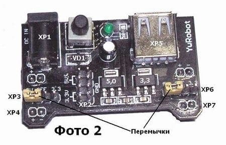
Power is supplied to the board through the XP1 universal connector and the SA1 pushbutton switch. To protect against polarity reversal of the connection, a protective diode VD1 is introduced into the circuit, and to indicate the inclusion of the supply voltage, an HL1 LED with a quenching resistor R1. Capacitors C1, C2, C3 and C4 are filter capacitors. From the SA1 switch, voltage is supplied to the AMS1117 5.0 stabilizer, the output voltage of which is five volts. Further, this voltage is supplied to the XP2, XP3, XP5, XP6 connectors and the second AMS1117 3.3 microcircuit stabilizer, the output voltage of which is 3.3 volts. The voltage at the XP4 and XP7 output connectors can be switched using the jumpers attached to the board, see photo 2. When working with this board, instead of these jumpers, current meters can be inserted into the circuit under study. When connecting voltmeters to pins 1, 5 or 2, 6 of the XP2 connector, you can control the supply voltage plus five volts. The voltage of +3.3 volts can be monitored by connecting a voltmeter to pins 3, 7 and 4, 8 of the same connector. The XP5 connector is a USB connector.
![]()
Separately, AMS1117 series stabilizers can be purchased via the Internet, as always, I ordered them via eBay from our friends from China. As you can see from the screenshot, the microcircuits are cheap, only 68 rubles for ten pieces. Microcircuits of this series are linear stabilizers for fixed output voltages - 1.2 V; 1.5V; 1.8V; 2.5V; 2.85 V; 3.3 V and 5.0 volts. The maximum allowable load current of these stabilizers is one ampere. The maximum input-output voltage is 1.3 V. The maximum input voltage is +15 V. The minimum load current is 0.01 A. These microcircuits are capable of operating in the temperature range from -40 to +125 degrees C. All microcircuits of this series have protection against exceeding load current and protection against excess temperature of the crystal. These stabilizers with additional elements are also capable of operating in regulated power supply circuits. AMS1117 1.2 chip switching circuit as adjustable stabilizer shown in Figure 2.
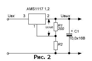
For this circuit, the output voltage is calculated by the formula Uout \u003d Ustab x (1 + R2 / R1). The voltage Ustab for the AMS1117 1.2 chip is 1.2 volts. The minimum voltage of such a stabilizer is limited from below by Ustab, and from above it is 15 V - 1.3 V = 13.7 V. Where 15 V is the maximum input voltage, and 1.3 volts is the voltage difference between the input and output of the stabilizer. All circuits using these microcircuits must have an output tantalum capacitor of 10 microfarads. This reduces current instability at high frequencies. It is also possible to use oxide electrolytic capacitors with a value of 50 microfarads or more, it is desirable to use a high-quality capacitor with an equivalent series resistance of 0.5 ohms.
Literature used: "Microcircuits for linear power supplies and their applications" Dodeka 1998.
Below are two 3 volt power supply circuits.
They collected on different elements, and you can choose a specific one yourself, having become acquainted with their features and based on your needs and capabilities.
The first figure shows simple circuit 3 V power supply(load current 200 mA) with electronic protection overload (Iz = 250 mA). The level of output voltage ripple does not exceed 8 mV.
For normal operation of the stabilizer, the voltage after the rectifier (on diodes VD1 ... VD4) can be from 4.5 to 10 V, but it is better if it is 5 ... 6 V, ≈ less source power is lost to heat dissipation by the transistor VT1 during operation stabilizer. The circuit uses the HL1 LED and diodes VD5, VD6 as a reference voltage source. The LED is also an indicator of the operation of the power supply.
Transistor VT1 is mounted on a heat-dissipating plate. How to calculate the size of a heat sink can be viewed in more detail.
Transformer T1 can be purchased from any unified TN series, but it is better to use the smallest TI1-127/220-50 or TN2-127/220-50. Many other types of transformers with a secondary winding of 5 ... 6 V are also suitable. Capacitors C1 ... C3 type K50-35.
The second circuit uses the integrated regulator DA1, but unlike the transistor regulator shown in the first figure, for the normal operation of the microcircuit, it is necessary that the input voltage exceed the output by at least 3.5 V. This reduces the efficiency of the stabilizer due to heat dissipation on the microcircuit.
With a low output voltage, the power lost in the power supply will exceed that given to the load. The required output voltage is set by the trimming resistor R2. The microcircuit is installed on the radiator. The integral stabilizer provides a lower level of output voltage ripple (1 mV), and also allows the use of smaller capacitances.
Integrated circuits of the LM2931 series manufactured by Motorola and Texas Instruments are linear voltage regulators of positive polarity with a low saturation voltage. These microcircuits are produced in TO-220, TO-263, DIP-8, TO-92 packages and are designed for fixed output voltages of 3.3V, 5.0V, there are also microcircuits of this series with adjustable output voltage. Microcircuits for a fixed output voltage are available in packages with three pins, microcircuits with an adjustable output voltage are available in packages with five and eight pins. The structural composition of microcircuits is shown in fig. 1, microcircuits for a fixed output voltage do not have “ADJ” and “ON / OFF” pins.
Having available microcircuits of the LM2931AZ-3.3 type, produced in a three-pin TO-92 package, you can assemble a simple stabilizer for an output voltage of +3.3 V, fig. 2. The stabilizer is designed for the input voltage range of +4...18 V, the maximum load current is 100 mA. The power dissipated by the microcircuit housing should not exceed 0.6 W. The maximum input operating voltage for all microcircuits of the LM2931 series is 26 V. The quiescent current of the author's copy of the stabilizer was 0.3 mA at an input voltage of 9 V with the load disconnected.
At a load current of 80 mA, the saturation voltage of the microcircuit was 0.35V, which means that at an output voltage of 3.3 V, the minimum input voltage of the stabilizer, at which stabilization of the output voltage is maintained, will be about 3.65 V. With a lower load current, the saturation voltage of the regulating two-collector pnp transistor Q1 will be smaller. If the input voltage of the stabilizer is less than the sum of the output voltage and saturation voltage, then the stabilizer quiescent current increases by several milliamps. The low quiescent current of the LM2931AZ-3.3 microcircuit and its low saturation voltage make it possible to use it as a voltage stabilizer in self-powered devices, for example, powered by lithium batteries with a nominal voltage of 3.7V, operated periodically, for example, small-sized radios, radio microphones, measuring instruments .
For devices operating around the clock from autonomous energy sources, it is advisable to use more economical integrated voltage regulators of positive polarity with a lower quiescent current, for example, LP2950, LP2951 (75 μA), MC78Vxx (50 μA), MC78FCxx (1.1 μA).
On fig. 3 shows a diagram of a power supply with a switchable output voltage. This functionally complete device is a power supply with a linear output voltage regulator, designed for a maximum load current of 1.5 A. The output voltage can be set to 3.3 V, 5.0 V, 6.5 V or 9.3 V. Voltage networks alternating current 220 V is supplied to the primary winding of the step-down transformer T 1 through the closed contacts of the switch SA 1, the fuse FU1 and the protective resistor R 1. An alternating current voltage of about 12 V through a polymer self-healing fuse FU2 is supplied to the bridge diode rectifier VD 1-VD 4, made on Schottky diodes.
The use of such diodes reduces the power and voltage losses on the rectifier bridge diodes by about half, in comparison with the rectifier bridge on conventional silicon diodes. Varistor RU 1 protects the transformer and Schottky diodes from mains voltage surges. The ripple of the rectified voltage is smoothed out by a high-capacity capacitor C 5. To increase the output current and power of the voltage stabilizer, a powerful discrete p-p-p transistor VT 1, which starts to open when the load current is more than 50 mA. Capacitor C 7 eliminates self-excitation of the DA 1 chip.
The output voltage of the stabilizer is selected using switch SA 2. When the switched contact is in the upper position according to the diagram, the output voltage of the stabilizer will be about 3.3 V. If the switch is set one step lower, then the output voltage of the stabilizer will increase by the total operating voltage of the series-connected Schottky diode VD 5 and LED HL 1. Capacitor C 8 reduces output voltage surges when changing the position of switch SA2. Resistor R4 reduces the discharge current of capacitor C8 when switching the output voltage from higher to lower. The saturation voltage of the stabilizer, assembled according to the scheme of fig. 3, without taking into account the voltage ripples at the terminals of the capacitor C 5 will be 1.5 V at a load current of 1.5 A, or 1.2 at a load current of 1 A, or 1 V at a load current of 0.5 V.
This is about two ... three times less than that of voltage stabilizers assembled on common microcircuits of integrated voltage stabilizers of the 78xx, 78Mxx, KR142ENxx series. When the load current changes from 0 to 1.5 A, the output voltage changes by no more than 10 mV.
If in a device assembled according to the scheme of Fig. 3, set capacitor C 8 with a capacity of 0.047 μF, exclude switch SA 2 and resistor R4, and instead of a chain of series-connected LEDs HL1 - HL3 and a Schottky diode VD 5, turn on a flashing single-color LED shunted by a low-power zener diode with an operating voltage of 9 V, for example, BZV55C- 9V1, and connect an incandescent lamp for an operating voltage of 12 ... 13.5 V to the output of the stabilizer, then such a lamp will flash in the pauses of the LED glow. In this case, it is desirable to install a capacitor C 10 with a capacity of 47 microfarads.
Most of the parts of the power supply, assembled according to the scheme of fig. 3 can be mounted on a 80x50mm PCB, fig. 4. The fuse FU1 is located in the fuse holder type DVP4-1, fixed on the body of the device. Varistor FNR-14K471 is soldered to the terminals of the primary winding of the step-down transformer. Instead of such a varistor, you can install FNR-20K471, MYG20-431, MYG20-471, LF14K471. Fixed resistors of types RPM, MLT, S1-4, S2-23, S2-33 or similar general use appropriate power. Oxide capacitors of types K50-35, K50-68 or imported analogues. Non-polar ceramic or small-sized film capacitors for an operating voltage of at least 25 V. Schottky diodes 1N5822 can be replaced with similar MBRS340T3, MBRS360T3, MBRD340, MBR340, MBR350, SR360, 5GWZ47. Diode SB140 can be replaced by any of 1N5817 - 1N5819, MBRS130LT3, MBR0520LT1, MBR0520LT3.
The Schottky diodes mentioned in the options for possible replacements are made in various cases. Transistor VT 1 must have a base current transfer ratio of at least 40 at a collector current of 1 A. It can be replaced by any of the KT818, 2T818, KT855, 2SA1293, 2SA1441, 2SA473 series. The transistor is mounted on a duralumin heat sink. The mentioned transistors have differences in pinouts and case type. Before installation, be sure to measure the base current transfer coefficient of the transistor, especially for powerful domestic transistors of the mentioned series, among which there are often instances with h21e less than 10. Microcircuits of the LM2931 series, produced in packages of various types, have differences in pinouts.
On circuit diagram the pinout for microcircuits in the TO-92 (KT-26) package is indicated - a plastic case like that of domestic transistors KT502, KT209. LEDs HL1, HL2 domestic red glow with a direct operating voltage of about 1.5V. The RL50-CB744D blue LED with a direct operating voltage of 2.8 V. The output voltage of the stabilizer depends on the operating voltage of the LEDs. Instead of LEDs, you can install several series-connected low-power silicon diodes, for example, KD522, 1N4148, or low-power zener diodes for the required operating voltage. Power switch SA1 small-sized keyboard type SS21 (4 A, ~250 V). Switch SA 2 of any type for 4 positions, free groups of contacts are connected in parallel. MF-R160 polymer resettable fuse can be replaced with LP30-160, LP60-160.
The unified step-down transformer TP8-25-220-50 can be replaced with TP8-26-220-50. These transformers have two secondary windings that must be connected in parallel, observing the phasing. Other transformers with an overall power of 20 ... 30 W are also suitable, secondary winding which is designed for an output voltage of 11 ... 14 V at a load current of 1.5 A. Resistor R 1 is set with a resistance approximately equal to half the resistance of the primary winding of the transformer.
Butov A.L.
Literature:
1.Miniature power transformersH.R. —
- Toroidal power transformersH.R. —Radioconstructor, 2011, No. 6, No. 9.
- Butov A.L. Chip StabilizersAMS1117-xx. - Radio constructor, 2008, No. 6, p. 24, 25.
- Butov A.L. Voltage stabilizers on the ICL88MS33T. —Radioconstructor, 2011, No. 11, p. 14-16.
- Butov A.L. Powerful low-voltage regulated power supplyLX8384-00CP. —
Radioconstructor, 2012, No. 11, p. 13-16.
Currently, many home devices require a stable voltage of 3 volts, and a load current of 0.5 amperes. These may include:
- Players.
- Cameras.
- Phones.
- Video recorders.
- Navigators.
These devices are united by the type of power source in the form of a battery or 3 volt batteries.
How to create power from a household network at home without spending money on batteries or batteries? For these purposes, it is not necessary to design a multi-element power supply, since special microcircuits are commercially available in the form of low voltage stabilizers.
3 volt stabilizer circuit
The depicted circuit is made in the form of an adjustable stabilizer, and makes it possible to create an output voltage from 1 to 30V. Therefore, this device can be used to power various devices for 1.5 V supply, as well as to connect devices to 3 volts. In our case, the device is used for the player, the output voltage is set to 3 V.
Circuit operation
With the help of a variable resistance, the required output voltage is set, which is calculated by the formula: U out \u003d 1.25 * (1 + R2 / R1). Instead of a voltage regulator, an SD1083 / 1084 microcircuit is used. Domestic similar microcircuits 22A / 142KREN 22 are used without changes, which differ in the output current, which is an insignificant factor.
For the normal mode of the microcircuit, it is necessary to mount a small radiator for it. Otherwise, with a low output voltage, the regulator operates in current mode, and heats up significantly even without load.
Mounting the stabilizer
The device is assembled on a circuit board with dimensions of 20 by 40 mm. The scheme is quite simple. It is possible to assemble the stabilizer without using the board, by surface mounting.
The finished board can be placed in a separate box, or directly in the case of the block itself. It is necessary first of all to adjust the operating voltage of the stabilizer at its output, using a regulator in the form of a resistor, and then connect the consumer load.
Switchable stabilizer on a chip
This scheme is the easiest and simplest. It can be mounted independently on a conventional LZ chip. By opening and closing the resistance in the feedback circuit, two different voltages are produced at the output. in this case, the load current can rise to 100 milliamps.

We must not forget about the pinout of the microcircuit, since it differs from conventional stabilizers.
Stabilizer on the chip AMS 1117
This is an elementary stabilizer with multiple fixed voltage adjustment positions of 1.5-5 V, current up to 1 ampere. It can be mounted independently on series - X.X (CX 1117 - X.X) (where XX is the output voltage).

There are samples of microcircuits for 1.5 - 5 V, with an adjustable output. They were used earlier on older computers. Their advantage is a low voltage drop and small dimensions. Two containers are required for installation. To remove heat well, install a radiator near the outlet.