Star news


Adjustable voltage stabilizer on lm317 circuit. Voltage stabilizer on LM317
The LM317 adjustable three-terminal positive voltage regulator provides 100 mA load current over an output voltage range of 1.2 to 37 V. The regulator is very easy to use and requires only two external resistors to provide output voltage. In addition, the LM317L stabilizer has better instability in voltage and load current than traditional stabilizers with a fixed output voltage.
Another advantage of the LM317L IC is that it is produced in a standard TO-92 transistor package, convenient for installation and installation. In addition to improved technical and operational performance compared to traditional stabilizers that have a fixed output voltage, the LM317L stabilizer has all (available only for IC) overload protection, including built-in internal current limiting circuits, overheating and safe area correction work.
All stabilizer overload protection functions also operate when the control terminal (ADJ) is disconnected. Under normal operating conditions, the LM317LHe regulator requires additional capacitors, unless the regulator IC is installed far from the primary power filter capacitor; In such a situation, an input bypass capacitor is required. An alternative output capacitor improves the transient performance of the stabilizer, and shunting the IC control pin with a capacitor increases the voltage ripple smoothing factor, which is difficult to achieve in other known three-terminal stabilizers.
In addition to replacing traditional fixed voltage regulators, the LM317 is suitable for a wide range of possible applications. So, in particular, the mode of operation of the stabilizer that “floats” based on the actual output voltage drop, in which the IC is affected only by the difference between the input and output voltage, allows it to be used in circuits with high-voltage stabilized power supply, and the operation of the stabilizer in such a circuit can continue indefinitely , until the difference between the input and output voltage exceeds the maximum permissible value.
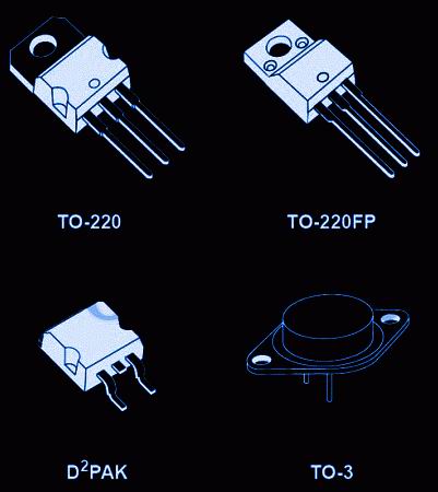
In addition, the LM317 is useful for creating very simple adjustable switching regulators, regulators with programmable output, or for creating a precision current regulator based on the LM317 by connecting a constant resistor between the control and output pins of the IC. The creation of secondary power supplies that remain operational during occasional short circuits of the output circuits is possible by fixing the voltage level at the control pin of the IC relative to ground, which programs the output voltage to be held at 1.2 V (for this voltage level, the current is quite small for the vast majority of types of loads ). The LM317L IC is produced in a standard TO-92 transistor package, and operates in the temperature range -25... +125"C.
Scheme charger on LM317 is given below. It uses a charging method DC. The charge current depends on the resistance R1. The resistance value should be in the range from 0.8 Ohm to 120 Ohm, which is equal to the charging current from 10 mA to 1.56 A:
Stabilized 5 Volt power supply with electronic switching:
15 volt power supply with soft start. The required smoothness of switching is set by the capacitance level of capacitor C2:
Scheme of an adjustable power supply for 2-30 Volts on LM317
The output voltage can be adjusted from 1.2 to 37 volts.
The powerful Darlington transistor Q1 is necessary to increase the current of the LM317, because without a heatsink, the microassembly can output only 100 mA current, but it is quite enough to control the transistor. D1 and D2 are protective diodes against overcharging of capacitors. 100 nF capacitors are installed in parallel with the electrolytic capacitors to reduce RF noise. It is advisable to place transistor Q1 on a radiator; the maximum output power of the power supply is 125 watts.
This circuit limits the current and ensures normal operation of the LED. This driver can power 0.2-5 watt LEDs from 9-25 Volts
With the help of a transformer, we lower the voltage from the 220 Volt variable to 25 Volts (you can use a transformer for another voltage convenient for you), then AC voltage turns into constant using the diode bridge spell and is smoothed out by capacitor C1, then to a highly stable voltage regulator
If you decide to convert your car to LED lightening, you will need at least an lm317 current stabilizer for LEDs. Assembling a basic stabilizer is not at all difficult, but in order to avoid disastrous mistakes even with such a simple task, a minimal educational program will not hurt. Many people not involved in radio electronics often confuse concepts such as current stabilizer and voltage stabilizer.
Easy about simple things. Current strength, voltage and their stabilization
Voltage determines how quickly electrons move through a conductor. Many passionate fans of hard computer overclocking increase the voltage of the central processor core, making it start to function faster.
Current strength is the density of electron movement within an electrical conductor. This parameter is extremely important for radioelements operating on the principle of thermionic secondary emission, in particular, light sources. If the cross-sectional area of the conductor is not able to pass the flow of electrons, excess current begins to be released in the form of heat, causing significant overheating of the part.
To better understand the process, let’s analyze the plasma arc (electric ignition of gas stoves and boilers works on its basis). At very high voltage the speed of free electrons is so high that they can easily “fly” the distance between the electrodes, forming a plasma bridge.
And this is an electric heater. When electrons pass through it, they transfer their energy to the heating element. The higher the current, the denser the flow of electrons, the more the thermoelement heats up.
Why is current and voltage stabilization necessary?
Any radio-electronic component, be it a light bulb or a computer's central processor, requires for optimal operation a clearly limited number of electrons that flow through the conductors.
Since our article is about a stabilizer for LEDs, we’ll talk about them.
With all their advantages, LEDs have one drawback - high sensitivity to power parameters. Even moderate excess of force and voltage can lead to burnout of the light-emitting material and failure of the diode.
Nowadays it is very fashionable to remodel a car's lighting system for LED lighting. Their color temperature is much closer to natural light than that of xenon and incandescent lamps, which makes the driver much less tired on long trips.
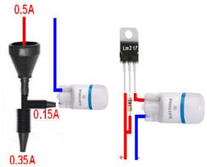
However, this solution requires a special technical approach. The rated supply current of a car LED diode is 0.1-0.15 mA, and the starting battery current is hundreds of amperes. This is enough to burn out a lot of expensive lighting elements. To avoid this, use a 12 volt stabilizer for LEDs in cars.
The amperage in a vehicle network is constantly changing. For example, a car air conditioner “eats” up to 30 amperes; when it is turned off, the electrons “allocated” to its operation will no longer return back to the generator and battery, but will be redistributed among other electrical appliances. If an additional 300 mA does not play a role in an incandescent lamp rated at 1-3 A, then several such surges can be fatal for a diode with a supply current of 150 mA.
To guarantee long-term operation of automotive LEDs, a current stabilizer based on lm317 is used for high-power LEDs.
Types of stabilizers
According to the method of limiting the current, there are two types of devices:
- Linear;
- Pulse.
It works on the principle of a voltage divider. It releases a current of a given parameter, dissipating the excess in the form of heat. The operating principle of such a device can be compared to a watering can equipped with an additional drain hole.
Advantages
- affordable price;
- simple installation diagram;
- easy to assemble with your own hands.
Disadvantage: due to heating, it is poorly suited to work with heavy loads.
Like a vegetable cutter, it cuts the incoming current through a special cascade, giving out a strictly dosed amount.
Advantages
- designed for high loads;
- does not heat up during operation.
Flaws
- requires a power source for its own operation;
- creates electromagnetic radiation;
- relatively high price;
- Difficult to make yourself.
Considering the low current in car LEDs, you can assemble a simple stabilizer for LEDs with your own hands. The most accessible and simple driver LED lamps and the tapes are assembled on the lm317 chip.
Brief description of lm317
The LM317 radio-electronic module is a microcircuit used in current and voltage stabilization systems.
- The voltage stabilization range from 1.7 to 37 V will ensure stable LED brightness, independent of engine speed;
- Support for output current up to 1.5 A allows you to connect several photo emitters;
- High stability allows fluctuations in output parameters of only 0.1% of the nominal value;
- Has built-in current limiting protection and a shutdown cascade for overheating;
- The microcircuit body is ground, so when fastened with a self-tapping screw to the car body, the number of mounting wires is reduced.
Application area
- Voltage and current stabilizer for LEDs in domestic conditions (including for LED strips);
- Voltage and current stabilizer for LEDs in cars;
Current stabilizer circuits for LEDs
 Circuit of the simplest stabilizer
 The simplest 12 volt voltage stabilizer can be assembled using this circuit. Resistor R1 limits the output current, R2 limits the output voltage. The capacitors used in this circuit reduce voltage ripple and increase operating stability.
The needs of the motorist will be satisfied by the simplest stabilization mechanism, since the supply voltage in the car network is quite stable.
To make a stabilizer for diodes in a car you will need:
- Chip lm317;
- Resistor as a current regulator for LEDs;
- Soldering and installation tools.
We assemble according to the above diagram
Calculation of a resistor for an LED driver
The power and resistance of the resistor are calculated based on the current strength of the power source and the current required by LEDs. For an automotive LED with a power of 150 mA, the resistor resistance should be 10-15 Ohms, and the calculated power should be 0.2-0.3 W.
How to assemble it yourself, watch the video:
The availability and simplicity of the driver design on the lm317 chip allows you to painlessly re-equip the electric lighting systems of any car.
In amateur radio practice, adjustable stabilizer microcircuits are widely used. LM317 And LM337. They have earned their popularity due to their low cost, availability, easy-to-install design, and good parameters. With a minimum set of additional parts, these microcircuits allow you to build a stabilized power supply with an adjustable output voltage from 1.2 to 37 V with a maximum load current of up to 1.5A.
But! It often happens that with an illiterate or inept approach, radio amateurs fail to achieve high-quality operation of microcircuits and obtain the parameters declared by the manufacturer. Some manage to get microcircuits into generation.
How to get the most out of these microcircuits and avoid common mistakes?
About this in order:
Chip LM317 is an adjustable stabilizer POSITIVE voltage, and the microcircuit LM337- adjustable stabilizer NEGATIVE voltage.
I would like to draw special attention to the fact that the pinouts of these microcircuits are various!
Click to enlarge
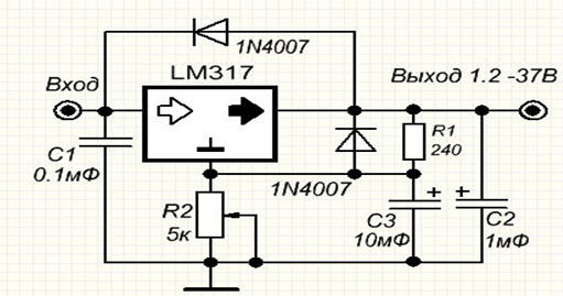
The output voltage of the circuit depends on the value of resistor R1 and is calculated by the formula:
Uout=1.25*(1+R1/R2)+Iadj*R1
where Iadj is the current of the control output. According to the datasheet it is 100 µA, as practice shows, the real value is 500 µA.
For the LM337 chip, you need to change the polarity of the rectifier, capacitors and output connector.
But the meager datasheet description does not reveal all the subtleties of using these microcircuits.
So, what does a radio amateur need to know to get from these microcircuits? MAXIMUM!
1. To obtain maximum input voltage ripple suppression, you must:
- Increase (within reasonable limits, but at least up to 1000 μF) the capacitance of the input capacitor C1. Having suppressed ripple at the input as much as possible, we will get a minimum of pulsation at the output.
- Bypass the control pin of the microcircuit with a 10 µF capacitor. This increases ripple suppression by 15-20dB. Setting a capacity larger than the specified value does not produce a noticeable effect.
The diagram will look like:
2. At output voltage more than 25V to protect the chip , To quickly and safely discharge capacitors, it is necessary to connect protective diodes:
Important: for LM337 microcircuits, the polarity of the diodes should be changed!
3. To protect against high-frequency interference, the electrolytic capacitors in the circuit must be bypassed with small-capacity film capacitors.
We get the final version of the scheme:
Click to enlarge
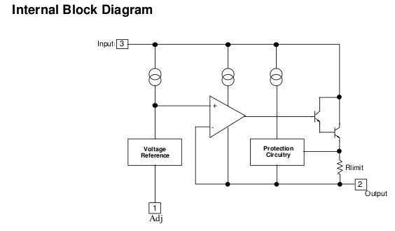
4. If you look internal structure of the microcircuits, you can see that 6.3V zener diodes are used inside some nodes. So normal operation of the microcircuit is possible at the input voltage not lower than 8V!
Although the datasheet says that the difference between the input and output voltages should be at least 2.5-3 V, one can only guess how stabilization occurs when the input voltage is less than 8V.
5. Particular attention should be paid to the installation of the microcircuit. Below is a diagram taking into account the wiring:
Click to enlarge
Explanations for the diagram:
- length of conductors (wires) from input capacitor C1 to the input of the microcircuit (A-B) should not exceed 5-7 cm. If for some reason the capacitor is removed from the stabilizer board, it is recommended to install a 100 µF capacitor in the immediate vicinity of the microcircuit.
- to reduce the influence of the output current on the output voltage (increasing current stability), resistor R2 (point D) must be connected directly to the output pin of the microcircuit or separate track/conductor ( section C-D). Connecting resistor R2 (point D) to the load (point E) reduces the stability of the output voltage.
- The conductors to the output capacitor (C-E) should also not be made too long. If the load is removed from the stabilizer, then a bypass capacitor (electrolyte 100-200 µF) must be connected on the load side.
- Also, in order to reduce the influence of the load current on the stability of the output voltage, the “ground” (common) wire must be separated "star" from the common terminal of the input capacitor (point F).
Happy creativity!
14 comments to “Adjustable stabilizers LM317 and LM337. Features of application"
- Chief Editor:
August 19, 2012Domestic analogues of microcircuits:
LM317 - 142EN12
LM337 - 142EN18
The 142EN12 chip was produced with different pinout options, so be careful when using them!
Due to the wide availability and low cost of original chips
It’s better not to waste time, money and nerves.
Use LM317 and LM337.
- Sergey Khraban:
March 9, 2017Hello, dear Editor-in-Chief! I am registered with you and I also really want to read the entire article and study your recommendations for using the LM317. But, unfortunately, I can’t view the entire article. What do I need to do? Please give me the full article.
Sincerely, Sergey Khraban
- Chief Editor:
March 10, 2017Are you happy now?
- Sergey Khraban:
March 13, 2017I am very grateful to you, thank you very much! All the best!
- Oleg:
July 21, 2017Dear Editor-in-Chief! I assembled two polar explorers on lm317 and lm337. Everything works great except for the difference in tension in the shoulders. The difference is not great, but there is a sediment. Could you tell me how to achieve equal voltages, and most importantly, what is the reason for such a imbalance? Thank you in advance for your answer. With wishes of creative success Oleg.
- Chief Editor:
July 21, 2017Dear Oleg, the difference in tension in the shoulders is due to:
2. deviation of the values of the setting resistors. Remember that resistors have tolerances of 1%, 5%, 10% and even 20%. That is, if the resistor says 2kOhm, its actual resistance can be in the region of 1800-2200 Ohms (with a tolerance of 10%)
Even if you install multi-turn resistors in the control circuit and use them to accurately set the required values, then... when the temperature changes environment the tension will still float away. Since resistors are not guaranteed to warm up (cool down) the same way or change by the same amount.
You can solve your problem by using circuits with operational amplifiers that monitor the error signal (difference in output voltages) and make the necessary adjustments.
Consideration of such schemes is beyond the scope of this article. Google to the rescue.
- Oleg:
July 27, 2017Dear editor! Thank you for your detailed answer, which prompted clarification - how critical is it for amplifier, preliminary stages, power supply with a difference in the arms of 0.5-1 volt? Regards, Oleg
- Chief Editor:
July 27, 2017The voltage difference in the arms is fraught, first of all, with asymmetrical limitation of the signal (at high levels) and the appearance of a constant component at the output, etc.
If the path does not have isolation capacitors, then even a slight constant pressure, which appears at the output of the first cascades, will be amplified many times over by subsequent cascades and will become a significant value at the output.
For power amplifiers with a power supply (usually) 33-55V, the voltage difference in the arms can be 0.5-1V; for preamplifiers it is better to keep within 0.2V.
- Oleg:
August 7, 2017Dear editor! Thank you for your detailed, thorough answers. And, if you allow, another question: Without load, the voltage difference in the arms is 0.02-0.06 volts. When the load is connected, the positive arm is +12 volts, the negative arm is -10.5 volts. What is the reason for this imbalance? Is it possible to adjust the equality of output voltages not at idle, but under load? Regards, Oleg
- Chief Editor:
August 7, 2017If you do everything correctly, then the stabilizers need to be adjusted under load. The MINIMUM load current is indicated in the datasheet. Although, as practice shows, it also works at idle.
But the fact that the negative leverage sags by as much as 2B is wrong. Is the load the same?
There are either errors in installation, or a left-handed (Chinese) microcircuit, or something else. No doctor will make a diagnosis over the phone or by correspondence. I also don’t know how to heal from a distance!
Have you noticed that LM317 and LM337 have different pin locations! Maybe this is the problem?
- Oleg:
August 8, 2017Thank you for your response and patience. I'm not asking for a detailed answer. We are talking about possible reasons, nothing more. Stabilizers need to be adjusted under load: that is, conditionally, I connect a circuit to the stabilizer that will be powered from it and set the voltages in the shoulders to be equal. Do I understand the process of setting up the stabilizer correctly? Regards, Oleg
- Chief Editor:
August 8, 2017Oleg, not very much! This way you can burn the circuit. You need to attach resistors (of the required power and rating) to the output of the stabilizer, adjust the output voltages, and only then connect the powered circuit.
According to the datasheet, LM317 has a minimum output current of 10mA. Then, with an output voltage of 12V, you need to attach a 1kOhm resistor to the output and adjust the voltage. At the input of the stabilizer there must be at least 15V!
By the way, how are the stabilizers powered? From one transformer/winding or different? When a load is connected, the minus drops by 2V - but how are things at the input of this arm?
- Oleg:
August 10, 2017Good health, dear editor! The trans wound itself, simultaneously two windings with two wires. The output on both windings is 15.2 volts. The filter capacitors are 19.8 volts. Today and tomorrow I will conduct an experiment and report back.
By the way, I had an incident. I assembled a stabilizer for 7812 and 7912, powered them with tip35 and tip36 transistors. As a result, up to 10 volts, the voltage regulation in both arms proceeded smoothly, the voltage equality was ideal. But above...it was something. The voltage was regulated intermittently. Moreover, while rising in one shoulder, it went down in the second. The reason turned out to be tip36, which I ordered in China. I replaced the transistor with another one, the stabilizer began to work perfectly. I often buy parts in China and have come to the following conclusion: You can buy, but you need to choose suppliers who sell radio components made in factories, and not in the workshops of some obscure individual entrepreneur. It turns out to be a little more expensive, but the quality is appropriate. Regards, Oleg.
- Oleg:
August 22, 2017Good evening, dear editor! Only today there was time. Trans with a midpoint, the voltage on the windings is 17.7 volts. I hung 1 kohm 2 watt resistors at the output of the stabilizer. The voltage in both shoulders was set to 12.54 volts. I disconnected the resistors, the voltage remained the same - 12.54 volts. I connected the load (10 pieces ne5532) and the stabilizer works great.
Thank you for your advice. Regards, Oleg.
Add a comment
Spammers, don't waste your time - all comments are moderated!!!
All comments are moderated!
You must leave a comment.
Component reference books (or datasheets) are essential
when developing electronic circuits. However, they have one unpleasant feature.
The fact is that documentation for any electronic component (for example, a microcircuit)
should always be ready even before this chip starts being produced.
As a result, in reality we have a situation where the microcircuits are already on sale,
and not a single product based on them has yet been created.
This means that all recommendations and especially application diagrams given in datasheets,
are theoretical and advisory in nature.
These circuits mainly demonstrate the operating principles of electronic components,
but they have not been tested in practice and should therefore not be blindly taken into account
during development.
This is a normal and logical state of affairs, if only over time and as
As experience accumulates, changes and additions are made to the documentation.
Practice shows the opposite - in most cases, all circuit solutions
presented in the datasheet remain at the theoretical level.
And, unfortunately, often these are not just theories, but gross mistakes.
And even more regrettable is the discrepancy between the real (and most important)
microcircuit parameters stated in the documentation.
As a typical example of such datasheets, here is a reference book for LM317, -
three-pin adjustable stabilizer voltage, which, by the way, is released
for about 20 years now. But the diagrams and data in his datasheet are still the same...
So, the disadvantages of the LM317 as a microcircuit and errors in the recommendations for its use.
1. Protective diodes.
Diodes D1 and D2 serve to protect the regulator, -
D1 is for input short circuit protection and D2 is for discharge protection
capacitor C2 “through the low output resistance of the regulator” (quote).
In fact, diode D1 is not needed, since there is never a situation where
the voltage at the regulator input is less than the output voltage.
Therefore, diode D1 never opens, and therefore does not protect the regulator.
Except, of course, in the case of a short circuit at the input. But this is an unrealistic situation.
Diode D2 can open, of course, but capacitor C2 discharges perfectly
and without it, through resistors R2 and R1 and through the load resistance.
And there is no need to specially discharge it.
In addition, the mention in the Datasheet of “C2 discharge through the regulator output”
nothing more than an error, because the circuit of the output stage of the regulator is
This is an emitter follower.
And capacitor C2 simply cannot be discharged through the regulator output.
2. Now - about the most unpleasant thing, namely the discrepancy between the real
electrical characteristics declared.
Datasheets of all manufacturers have the Adjustment Pin Current parameter
(current at the trim input). The parameter is very interesting and important, determining
in particular, the maximum resistor value in the input circuit Adj.
And also the value of capacitor C2. The declared typical current value Adj is 50 µA.
Which is very impressive and would completely suit me as a circuit designer.
If in fact it were not 10 times larger, i.e. 500 µA.
This is a real discrepancy, tested on microcircuits from different manufacturers
and for many years.
It all started with bewilderment - why is there such a low-resistance divider at the output in all circuits?
But that’s why it’s low-resistance, because otherwise it’s impossible to get LM317 at the output
minimum voltage level.
The most interesting thing is that in the current measurement technique Adj the low-resistance divider
is also present at the output. What it actually means is that this divider is on
parallel with electrode Adj.
Only with such a cunning approach can you “fit” within the typical value of 50 μA.
But this is a rather elegant trick. "Special measurement conditions."
I understand that it is very difficult to achieve a stable current of the declared value of 50 μA.
So don't write a lie in the Datasheet. Otherwise, it is a deception of the buyer. And honesty is the best policy.
3. More about the most unpleasant thing.
Datasheets LM317 has a Line Regulation parameter that determines
operating voltage range. And the indicated range is not bad - from 3 to 40 Volts.
There's just one small BUT...
The internal part of the LM317 contains a current stabilizer that uses
Zener diode for voltage 6.3 V.
Therefore, effective regulation starts with an Input-Output voltage of 7 Volts.
In addition, the output stage of the LM317 is npn transistor, included according to the scheme
emitter follower. And on the “boost” he has the same repeaters.
Therefore, effective operation of the LM317 at a voltage of 3 V is impossible.
4. About circuits that promise to obtain an adjustable voltage from zero volts at the output of LM317.
The minimum output voltage of LM317 is 1.25 V.
It would have been possible to get less if it were not for the built-in protection circuit against
short circuit at the output. Not the best scheme, to put it mildly...
In other microcircuits, the short circuit protection circuit is triggered when the load current is exceeded.
And in LM317 - when the output voltage drops below 1.25 V. Simple and tasteful -
The transistor shuts down when the base-emitter voltage is below 1.25 V and that’s it.
That's why all application schemes that are promised to be output
LM317 adjustable voltage, starting from zero volts - do not work.
All these circuits suggest connecting the Adj pin through a resistor to the source
negative voltage.
But already when the voltage between the output and the Adj contact is less than 1.25 V
the short circuit protection circuit will work.
All these schemes are pure theoretical fantasy. Their authors do not know how the LM317 works.
5. The output short circuit protection method used in LM317 also imposes
known restrictions on starting the regulator - in some cases starting will be difficult,
since it is impossible to distinguish between short-circuit mode and normal switching mode,
when the output capacitor is not yet charged.
6. Recommendations for capacitor values at the output of LM317 are very impressive -
this range is from 10 to 1000 µF. What in combination with the value of the output resistance
a regulator of the order of one thousandth of an ohm is complete nonsense.
Even students know that the capacitor at the input of the stabilizer is essential
to put it mildly, more efficiently than the output.
7. About the principle of LM317 output voltage regulation.
LM317 is operational amplifier, in which regulation
The output voltage is carried out via the NOT inverting input Adj.
In other words - along the Positive Feedback Circuit (POC).
Why is this bad? And the fact that all interference from the regulator output through the Adj input passes inside the LM317,
and then - again to the load. It’s good that the transmission coefficient along the PIC circuit is less than one...
Otherwise we would get a self-generator.
And it is not surprising in this regard that it is recommended to install capacitor C2 in the Adj circuit.
At least somehow filter out interference and increase resistance to self-excitation.
It is also very interesting that in the PIC circuit, inside LM317,
There is a 30 pF capacitor. Which increases the level of ripple on the load with increasing frequency.
True, this is honestly shown in the Ripple Rejection diagram. But what is this capacitor for?
It would be very useful if regulation was carried out along the circuit
Negative feedback. And in terms of PIC value, it only worsens stability.
By the way, with the concept of Ripple Rejection itself, not everything is “in terms of concepts”.
In the generally accepted understanding, this value means how well the regulator
filters ripples from the INPUT.
And for LM317 it actually means the degree of its own damage
and shows how well the LM317 fights ripples, which itself
takes it from the exit and again drives it inside itself.
In other regulators, regulation is carried out through a circuit
Negative feedback, which maximizes all parameters.
8. About the minimum load current for LM317.
The Datasheet specifies a minimum load current of 3.5 mA.
At lower current, LM317 is inoperative.
A very strange feature for a voltage stabilizer.
So, you need to monitor not only the maximum load current, but also the minimum one?
This also means that with a load current of 3.5 mA, the efficiency of the regulator does not exceed 50%.
Thank you very much, gentlemen, developers...
1. Recommendations for the use of protective diodes for LM317 are of a general theoretical nature and consider situations that do not occur in practice.
And, since it is proposed to use powerful Schottky diodes as protective diodes, we get a situation where the cost of (unnecessary) protection exceeds the price of the LM317 itself.
2. The Datasheets LM317 contains an incorrect parameter for the current at the Adj input.
It is measured under “special” conditions when connecting a low-impedance output divider.
This measurement technique does not correspond to the generally accepted concept of “input current” and shows the inability to achieve the specified parameters during the manufacture of LM317.
It also deceives the buyer.
3. The Line Regulation parameter is specified as a range from 3 to 40 Volts.
In some application circuits, the LM317 “operates” with an input-output voltage of as much as two volts.
In fact, the range of effective regulation is 7 - 40 Volts.
4. All circuits for obtaining regulated voltage at the output of LM317, starting from zero volts, are practically inoperable.
5. The LM317 short circuit protection method is sometimes used in practice.
It's simple, but not the best. In some cases, starting the regulator will not be possible at all.
7. LM317 implements a defective principle of output voltage regulation -
along the Positive Feedback circuit. It should be worse, but it couldn’t be worse.
8. The limitation on the minimum load current indicates poor circuit design of the LM317 and clearly limits its use.
Summarizing all the shortcomings of the LM317, we can give recommendations:
a) To stabilize constant “typical” voltages of 5, 6, 9, 12, 15, 18, 24 V, it is advisable to use three-terminal stabilizers of the 78xx series, and not LM317.
b) To build truly effective voltage stabilizers, you should use microcircuits like LP2950, LP2951, capable of operating at an input-output voltage of less than 400 millivolts.
Combined with high-power transistors if necessary.
These same microcircuits also work effectively as current stabilizers.
c) In most cases, an operational amplifier, a zener diode and a powerful transistor (especially a field-effect transistor) will give much better parameters than the LM317.
And certainly - the best adjustment, as well as the widest range of types and values of resistors and capacitors.
G). And, don't blindly trust Datasheets.
Any microcircuits are made and, which is typical, sold by people...

