Star news


Laying a high voltage cable in the ground. Laying cables in the ground
Julia
Hello! In our yard between two multi-storey buildings, a high-voltage cable was laid underground; the area has now been paved and a parking lot has been made. Are the actions legal? Thanks for the help.
Answer:
The cable laying under the asphalt parking lot was carried out in accordance with current standards and requirements. When laying cables under asphalt surfaces with heavy traffic, cable lines must be laid in pipes or blocks to a depth of at least 1 meter from the planning mark.
Laying cables in the ground under roads
PUE-6
2.3.17. The designs of underground cable structures must be calculated taking into account the mass of cables, soil, road surface and load from passing traffic.
2.3.30
In streets and squares saturated with underground communications, it is recommended to lay 10 or more cable lines in a stream in collectors and cable tunnels. When crossing streets and squares with improved surfaces and heavy traffic, cable lines should be laid in blocks or pipes.
2.3.83
When laying cable lines directly in the ground, the cables must be laid in trenches and have a backfill on the bottom and a layer of fine earth on top that does not contain stones, construction waste and slag.
Cables along their entire length must be protected from mechanical damage by covering them at voltages of 35 kV and above with reinforced concrete slabs with a thickness of at least 50 mm; at voltages below 35 kV - with slabs or ordinary clay bricks in one layer across the cable route; when digging a trench with an earth-moving mechanism with a cutter width of less than 250 mm, as well as for one cable - along the route cable line.
The use of silicate, as well as clay hollow or perforated bricks is not allowed.
When laid at a depth of 1 - 1.2 m, cables of 20 kV and below (except for city power supply cables) may not be protected from mechanical damage.
Cables up to 1 kV should have such protection only in areas where mechanical damage is likely (for example, in places of frequent excavation). Asphalt street surfaces, etc. are considered as places where excavations are carried out in rare cases. For cable lines up to 20 kV, except for lines above 1 kV supplying electrical receivers of category I*, it is allowed in trenches with no more than two cable lines to use signal plastic tapes instead of bricks that meet the technical requirements approved by the USSR Ministry of Energy. It is not allowed to use warning tapes at the intersections of cable lines with utility lines and over-cable couplings at a distance of 2 m in each direction from the crossed utility line or coupling, as well as at the approaches of lines to switchgears and substations within a radius of 5 m.
____________
* According to local conditions, with the consent of the line owner, it is allowed to expand the scope of application of signal tapes.
The signal tape should be laid in a trench above the cables at a distance of 250 mm from their outer covers. When placing one cable in a trench, the tape must be laid along the axis of the cable; with a larger number of cables, the edges of the tape must protrude beyond the outermost cables by at least 50 mm. When laying more than one tape across the width of a trench, adjacent tapes must be laid with an overlap of at least 50 mm wide.
When using signal tape, laying cables in a trench with a cable cushion, sprinkling the cables with the first layer of earth and laying the tape, including sprinkling the tape with a layer of earth along the entire length, must be carried out in the presence of a representative of the electrical installation organization and the owner of the electrical networks.
2.3.84
The depth of cable lines from the planning mark must be no less than: lines up to 20 kV 0.7 m; 35 kV 1 m; when crossing streets and squares, regardless of voltage 1 m.
Oil-filled cable lines 110 - 220 kV must have a laying depth from the planning mark of at least 1.5 m.
It is allowed to reduce the depth to 0.5 m in sections up to 5 m long when entering lines into buildings, as well as where they intersect with underground structures, provided that the cables are protected from mechanical damage (for example, laying in pipes).
The laying of 6-10 kV cable lines across arable land must be done at a depth of at least 1 m, while the strip of land above the route can be occupied for crops.
2.3.97
When cable lines cross railways and highways, the cables must be laid in tunnels, blocks or pipes across the entire width of the exclusion zone at a depth of at least 1 m from the roadbed and at least 0.5 m from the bottom of drainage ditches. In the absence of an exclusion zone, the specified laying conditions must be met only at the intersection plus 2 m on both sides of the road surface.
When crossing cable lines that are electrified and subject to electrification at DC* railways blocks and pipes must be insulating (see 2.3.90). The intersection must be at a distance of at least 10 m from the arrows, crosses and points of connection of suction cables to the rails.
The intersection of cables with the tracks of electrified rail transport should be made at an angle of 75 - 90° to the axis of the track.
_____________
* Agreed with the Ministry of Railways.
The ends of blocks and pipes must be insulated with jute braided cords coated with waterproof (crumpled) clay to a depth of at least 300 mm.
When crossing dead-end industrial roads with low traffic intensity, as well as special paths (for example, on slips, etc.), cables, as a rule, should be laid directly in the ground.
When the route of cable lines crosses a newly constructed non-electrified railway or highway, relocation of existing cable lines is not required. At the intersection, reserve blocks or pipes with tightly sealed ends should be laid in the required quantity in case of cable repairs.
In the case of a transition of a cable line into an overhead line, the cable must exit to the surface at a distance of at least 3.5 m from the base of the embankment or from the edge of the canvas.
2.3.99
When cable lines cross vehicle entrances to courtyards, garages, etc. Cables must be laid in pipes. Cables at intersections of streams and ditches should be protected in the same way.
Read also:
Elena Good afternoon! Please tell me in what cases is it possible to lay cables in the ground in steel tubes? And in what literature can you read about this? Answer: Cable laying in the ground is carried out in asbestos-cement pipes, ...
Dmitry Please tell me the answer to the question: power (VVG) and low-current cables in HDPE pipes are laid across the territory of the cottage. Is it necessary at the places where they intersect with gas or heat pipelines according to the document...
Nadezhda Tell me, please, how far should a high-voltage cable laid underground from a residential building be removed? Is there any SNiP for laying such a cable? Answer: When laying cables in the ground, the distance...
Alexey Hello! This is the situation: a wooden 2-story school combined with a kindergarten (1st floor kindergarten, 2nd school), air entry, the support stands about five meters from the school to the fence of the school territory, that is, on the school...
Sergey A neighbor in the garden plot laid a power cable in the ground, from the overhead line pole to his house right under the fence. Is it possible to carry out such electrical installation? In winter, the fence posts will “play” and may...
6 Comment(s) on “Do they have the right to lay cable under a paved parking lot?”
-
Hello, Ivan!
Your question has been redirected to . You can register on the forum and discuss "" in more detail with forum participants. Hello, Alexander!
Your question has been redirected to . You can register on the forum and discuss in more detail "
The question is this: there are existing cables 2 x 0.4 kW and 2 x 10 kW (underground), mountains. the network doesn’t mind us crossing them, building a building with a 2-story ceiling and a concrete floor. It turns out that the cables will pass under the building, there is no basement, they are required to provide a solution for the intersection in order to issue a building permit. Are there any typical solutions?
Cable is one of the main elements of power supply for enterprises or residential buildings. Cable laying methods are selected based on the cost and speed of work, as well as technical project- by air, in blocks, pipes, in a trench, using supports or trays.
Placing the cable in an earthen trench is one of the cheapest types of cable installation. Laying a high-voltage cable in the ground is developed and implemented in such a way as to eliminate the possibility of mechanical damage to the cable during operation. Laying an electrical cable in the ground gives a big plus to the organization of cable cooling using the ground.
Cable line laying technology
According to the technology, the cable is laid with a small margin in case of mechanical displacement of the soil and taking into account deformation due to temperature changes. In practice, this means wavy laying of the cable if we are talking about placing it in a trench, and creating a sag if the cable is laid along structures. Creating cable rings for reserve is unacceptable. In the case of vertical installation, rigid fastening is used in the form of gaskets made of sheet rubber, polyvinyl chloride or elastic material designed for the appropriate temperature range.
Installation is carried out in two stages - the creation of supporting structures for installation and the direct work on laying the cable and connecting it to the terminals. Indoors and in places outside accessible to unqualified personnel, as well as where there is the possibility of movement of vehicles, transshipment of goods and operation of mechanisms, I lay cables at a height of more than 2 meters.
Cable laying standards
According to standards, the cable must be laid to a depth of at least 0.7 meters. In one trench it is allowed to place no more than 6 cores (at a voltage of 6-10 kW) and no more than two, at a voltage of 35 kW. The width of the trench should be selected based on the convenience of work; however, it should be at least 20 cm for voltages up to 10 kW, and at least 30 cm for 35 kW. If there are more than 20 cables, it is justified to organize their placement in the tunnel.
Tests
The cable is delivered to the site in its original packaging - a drum. After removing the outer shell of the drum, it is necessary to evaluate the condition of the insulation shell of the outer turns for leaks, cracks, displacements or gaps between the turns of the armor tape. The cable damaged during transportation is removed, and the remaining cable is tested with increased voltage.
Laying the control cable in the ground must be accompanied by a test of its wave resistance in order to detect malfunctions or damage caused during installation.
When laying cables at subzero temperatures, it is necessary to take into account the ambient temperature. Provided that the cable is heated indoors, the speed of its installation outdoors is selected from the following temperatures:
- From 0 to minus 10 degrees - installation time no more than an hour;
- From minus 10 to 20 degrees - installation time no more than 40 minutes;
- At temperatures below 20 degrees, installation time should not exceed 30 minutes.
At temperatures below 40 degrees, laying cable of any brand is prohibited. Laying cables in the ground, inspection of electrical equipment, electrical testing, installation and many other works related to electrical equipment can be carried out by the 10 Kilovolt company. At your service is a staff of highly qualified specialists and their invaluable experience.
Video: laying a high-voltage cable in the ground
Conditions and advantages of underground cable laying
Laying cables in the ground is the most economical. In addition, unlike overhead lines, cable installation in the ground is not subject to heavy snowfalls, storm winds and is not damaged by fallen trees. Cable lines are less susceptible than overhead lines to dangerous and interfering electromagnetic influences created in communication, signaling, automation and telemechanics circuits by various power lines and contact networks electric railways, as well as the effects of atmospheric overvoltages (lightning discharges).
Cable lines better ensure uninterrupted operation, high quality and reliability of communication and signaling devices, are more durable and cheaper to operate, although their construction is more expensive. Damage on cable lines occurs much less frequently than on overhead lines.
For cable lines laid in the ground, armored cables should be used predominantly. The metal sheaths of these cables must have an outer covering to protect them from chemical attack. If unarmored cables are laid, then you must first lay asbestos-cement or PVC pipes, which will reliably protect it from
accidental mechanical damage during subsequent excavations. If the cable is armored, then its use will also require laying pipes at the intersection of railway and tram rails, highways and dirt roads, under roadways, at intersections with underground structures and other cables so that the ends of the pipes extend 1 m beyond the intersection, as well as when entering the cable into a building or structure.
Cables are protected when they are laid in rocky soils at a depth of 0.5 m, in gardens and orchards, when laying ten or more signal and other cables in one trench, as well as when laying power cables with an operating voltage higher in a trench at a depth of less than 1 m 1 kV. In these cases, the cable is covered with concrete slabs or a layer of red brick for protection.
The entire procedure for underground cable laying includes several stages:
- selection and approval of the cable route,
- marking and layout of the route,
- digging a trench,
- arrangement of bedding (pillow) from fine earth without stones or sand,
- laying protective pipes (if provided for by the project),
- preparing the cable for installation,
- laying the cable (if the cable is laid in pipes, then pulling the cable in pipes),
- installation of couplings,
- backfilling the cable with fine earth without stones or sand,
- cable protection with red clay bricks or asbestos cement slabs,
- laying warning tape (if provided for by the project),
- drawing up a hidden work report,
- electrical laboratory tests of the cable line and backfilling of the trench with soil.
All these electrical installation works must be carried out in the sequence in which they are listed.
Selecting a cable route
The cost of constructing cable lines and networks, their durability, as well as reliability and uninterrupted operation depend on the correct choice of route. The route of underground cable lines is selected based on the fact that the length of the cable laid between given points is the shortest and ensures ease of work on laying the cable and its further operation. maintenance and operation.
Any electrical installation work associated with excavating the ground and laying cables in the ground must begin only after obtaining permission to lay the cable, since other engineering systems may be laid in the ground, and you can damage them, or lay the cable in violation of existing standards.
If excavation work is carried out in populated areas, then before it begins, the customer is obliged to obtain a permit from the territorial administration to carry out the work envisaged by the project and transfer it to the contractor.
The contractor is required to obtain a work order based on the permit.
The order specifies:
a) last name, first name, patronymic and position of the person responsible for the work;
b) the deadline for completing construction work at the site, linked to the submitted work project;
c) organizations that are entrusted with the work of restoring road surfaces, replanting green spaces and the timing of this work;
d) organizations whose representatives must be called to the site before the start of excavation work.
Working documentation, a warrant for the right to carry out work and a copy of the written notification document must be located at the place of work.
Excavation work within the security zones of existing underground structures (power and communication cables, pipelines, etc.), as well as above-ground structures when crossing them (railways, highways), when laying cables along the side of the road, etc. is allowed only if there is written permission of the organization operating these structures and in the presence of its representative, as well as the responsible performer of the work. Work in such places must be agreed upon and reflected in the design documentation.
The construction organization is obliged, no later than three days before the start of excavation work, to notify in writing about the upcoming work, and one day before - to call representatives of interested organizations to the work site to clarify the location of the structures they own and agree on measures to prevent damage to these structures. Until the representatives arrive, excavation work is prohibited.
Before digging a trench, the route must be inspected to identify places on the route containing substances that have a destructive effect on the cable sheath (salt marshes, lime, water, bulk soil containing slag or construction waste, areas located closer than 2 m from sewage, cesspools and garbage pits and so on.). If it is impossible to bypass these places, the cable should be laid in clean neutral soil in asbestos-cement pipes with additional sealing. When backfilling the cable with neutral soil, the trench should be further expanded on both sides by 0.5-0.6 m and deepened by 0.3-0.4 m.
Laying underground cable and cable duct in populated areas it is advisable to carry out along the streets,
In cities and towns, cables are laid in the ground (in trenches) along impassable parts of streets (under sidewalks), along courtyards and technical strips in the form of lawns, with bush plantings that have the least load of other underground structures (water supply, sewerage, gas pipelines, power cables etc.), so as to reduce disruption to street traffic during work on laying the cable line and its operation. In streets and squares saturated with underground communications, it is recommended to lay cable lines in collectors and tunnels. When crossing streets and squares with improved surfaces and heavy traffic, cable lines should be laid in blocks or pipes.
Preliminary trenching must be carried out to accurately identify underground structures crossed by the route of the laid communication cable or cable drainage pipeline.
The pits should have a length of 1 m along the axis of the future trench. In the case where underground structures run parallel to the future route, pits must be dug perpendicular to its axis every 20 m. The length of each pit must exceed the width of the designed trench on each side by no less than 0.3 m.
If, during excavation work, underground structures that are not indicated in the working drawings are discovered, the work must be stopped immediately until the purpose of these structures is clarified and further work is agreed upon with their owners.
When laid in the ground in parallel with other cables or utility lines in use near buildings and structures, clear distances (not less) must be maintained;
- between cables up to 10 kV - 0.1 m (the same distance when laying newly laid cables in parallel);
- from 35 kV cables - 0.25 m (Fig. 1.1);
- from cables operated by other organizations and communication cables - 0.5 m (Fig. 1.2);
- from the cable to forest plantations - at least 3 m, from tree trunks - 2 m and from artisanal plantings - 0.75 m (Fig. 1.3);
- from the foundations of buildings and structures - 0.6 m (Fig. 1.4);
- from pipelines, water supply, sewerage, drainage, low and medium pressure gas pipelines - 1 m (Fig. 1.5);
- from high-pressure gas pipelines and heat pipelines - 2 m (Fig. 1.6);
- from the electrified railway - 10.75 m (Fig. 1.7);
- from tram tracks - 2.75 m (Fig. 1.8);
- from the highway from the edge - 1 m;
- from the curb stone - 1.5 m (Fig. 1.9);
- from the outermost wire of a 110 kV overhead line - 10 m (Fig. 1.10);
- from the support of a 1 kV overhead line - 1 m (Fig. 1.11).
Rice. 1.1. Laying 1-10 kV cables in parallel with 35 kV (20 kV) cables:
1 - cable 20 kV;
2 - cable 35 kV;
3 - 10 kV cable;
4 - sand;
5 - reinforced concrete slabs
Rice. 1.2. Laying 1-10 kV cables with communication cables and power cables up to 10 kV, operated by other organizations:
1 - 10 kV cable; 2 - cable 1 kV; 3 - communication cable or power cable of another organization; 4 - sand; 5 - bricks or slabs
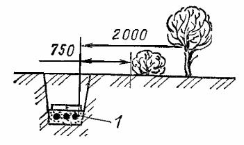
Rice. 1.3. Laying cables near bushes and trees:
1 - cable 1-10 kV
![]()
Figure 1.4. Laying cables near the foundation of a building and structures:
1 - cable 1-10 kB; 2 - foundation

Rice. 15. Laying cables parallel to pipelines, water pipes, sewerage, drainage, low and medium pressure gas pipelines:
1 - pipeline; 2 - cable 1-10 kV

Rice. 16. Laying cables near heating mains and high-pressure gas pipelines:
1 - tray; 2 - cable 1-10 kV
![]()
Figure 1.7. Laying cables parallel to an electrified railway:
1 - cable 1-10 kV; 2 - rail head
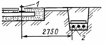
Rice. 1.8. Laying cables parallel to tram tracks:
1 - rail head; 2 - cable 1-10 kV
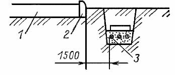
Rice. 1.9. Laying cables parallel to the road:
1 - road surface; 2 - curb stone; 3 - cable 1-10 kV
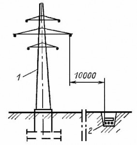
Rice. 1.10. Laying cables next to a 110 kV overhead power line:
1 - overhead line support; 2 - cable 1-10 kV
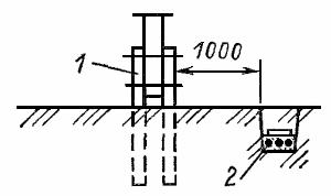
Rice. 1.11. Laying cables next to an overhead power line up to 1 kV:
1 - overhead line support; 2- cable 1-10 kV
It is possible to reduce the listed distances in cramped conditions, but this must be specified in the project and measures must be provided to protect cables in pipes or blocks.
When crossing other cable lines or utilities and structures, the clear distances should be no less than:
- from cables with voltage up to 10 kV - 0.25 m (Fig. 1.9);
- from pipelines, heat pipelines, gas pipelines - 0.5 m (Fig. 1.10);
- from railway tracks, tram tracks, highways - 0.6 m.
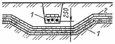
Rice. 1.12. Crossing cable routes with voltage up to 10 kV:
1 - cable up to 10 kV; 2 - bricks
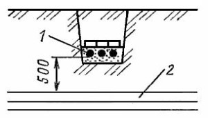
Rns. 1.13. Crossing cables with pipes, water and gas pipelines:
1 - cable up to 10 kV; 2 - pipeline
In the event of accidental damage to any underground structure, the responsible contractor is obliged to immediately stop work in this place, take measures to ensure the safety of workers, and report the incident to his supervisor and the emergency service of the operating organization.
If gas is detected in trenches or pits, work in them must be stopped immediately, and people must be removed from the danger zone. Work can be continued only after further gas flow has ceased.
All structures damaged during trenching (ditches, drains, ditches, channels, embankments, improved coverings, fences, etc.) must be restored.
On arable lands, the fertile soil layer must be reclaimed. The scope and conditions for performing reclamation work are determined by the project documentation.
Signal cables can be laid without restrictions in the same trench with power cables with operating voltages up to 500 V
When crossing them with power cables and other underground structures, signal cables must also be laid at a distance of 0.5 m from these structures;
if this distance cannot be maintained due to local conditions, then it is allowed to reduce it to 0.3 m. In this case, at the intersection of the signal cable with the power cables, it must be laid in an asbestos-cement pipe. The distance between signal cables crossing each other must be at least 0.1 m.
Marking and laying out the route, preparing trenches for laying cables
Before laying the cable, the route is laid out, which is selected during the design process taking into account the least amount of construction work, maximum use of mechanisms, ease of maintenance and minimal costs for work to protect cables from corrosion, hazardous influences and damage from lightning strikes. The route is laid out in accordance with the working drawings, deviations from which are allowed only by agreement with the customer or design organization.
The cable route is chosen to be as straight as possible. Areas with calcareous soils, wastewater, landfills and other places that are dangerous in terms of corrosion should be avoided. The locations of existing underground structures are determined by technical documentation or using cable detectors and by pitting.
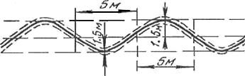
On the slopes of ravines, steep ascents and descents over 30° and up to 45°, the trench should be dug in a zigzag (“snake”) pattern, with a maximum deviation from the axial straight line of 1.5 m over a length of 5 m. For slopes from 30° to 45° the cable is laid with conventional armor, and for slopes over 45° - with wire armor.
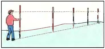
The marking and layout of the underground cable line route is carried out in accordance with the working drawings using poles and/or pegs in the center of the future trench and at its turns, as well as on straight sections, after about 50 m along its length, stakes are hammered in, which serve as starting points. points for laying out the trench.
If the route comes in places where there are no permanent landmarks, the breakdown is carried out as follows. In the excavation centers of two adjacent pits, a first milestone with a height of 3 to 4 m with a red flag is installed for the viewing device, after 40-50 m a second milestone is placed (in the turning or main intermediate center) so that it can be seen from the side of the first milestone, and In this way, two points are obtained on the axis of the trench, the third pole is made in the interval between poles No. 1 and 2. Then, between the first and second poles, pole No. 3 is installed so that it is in alignment (on the same straight line) with the first and second poles. The third and subsequent milestones are installed from the side of the first every 40 to 50 m.
The installation sites of the poles are fixed with pegs. Pegs used to mark routes should have a length of 30 to 40 cm and a diameter of 3 to 4 cm. The lower part of the peg is hewn at the end, and a cut is made on the upper part for marking. To drive a peg, prepare a nest using a crowbar. Pegs should be driven into the ground to a depth of 100 to 150mm.
At a distance equal to half the width of the trench from the pegs, a cord should be pulled, marking the line of one of the edges of the trench.
If there are permanent landmarks, the route can be laid out without sightings along the milestones. The final route is marked with a breaker cord, drawing two parallel lines with chalk or paint, which determine the required width of the trenches.
In the event that the breakdown reveals a discrepancy between the working drawings and the need to perform work deviating from the design data, the construction organization must invite representatives of the customer and the design organization to resolve the issue of changing the route, which is formalized by an act or correction of the working drawing, which must be certified signatures of representatives of the customer, design and interested organizations.
When laying out routes, the following must be taken into account:
a) the intersection of streets with underground civil engineering structures should be carried out at an angle of 90° to the axis of the street, only if this is not possible, a deviation from the right angle within no more than 45° is allowed;
b) the intersection of rail tracks (railway and tram) with underground hydraulic structures should only be carried out at an angle of 90°;
c) in gardens, parks and public gardens, the layout of routes should be carried out in the presence of a representative of landscape gardening and green construction, taking into account the least damage to green spaces.
When laying cables in the ground, it is necessary to maintain the distances from above-ground and underground structures specified in the design documentation.
When working within the security zones of underground communications, the responsible executor of the work is obliged to instruct, against receipt, the foreman and drivers working on the mechanisms about the conditions of work, show the locations of underground communications according to drawings and in kind, mark the boundaries within which it is prohibited to work with the help of earth-moving equipment mechanisms, as well as use impact mechanisms.
If a cable route is planned in places where there are already existing cables or other underground structures that are not clearly indicated on the street drawing, then before starting to dig a trench, it is necessary to check the location of these structures in relation to the route. For this purpose, test pits are dug along the entire route - test pits, which should have a length of 1 m along the axis of the future trench. In the case where underground structures run parallel to the future route, pits must be dug perpendicular to its axis every 20 m. The length of each pit must exceed the width of the designed trench on each side by no less than 0.3 m.
The depth of the pits, if the structures being sought are not found, must exceed the depth of the trench by 0.2 m. The pitting must be carried out in the presence of a representative of the organization operating the underground structures.
Underground structures exposed during excavation and trenching must be protected by a special box and suspended in the manner specified in the working drawings.
The route of the laid underground cable can be clarified with a special cable detector. With a cable laying depth of up to 2 m, the device determines its location with an accuracy of 10 cm and operates regardless of road surfaces.
When crossing trenches with existing underground utilities, mechanized soil development is permitted at a distance of no more than 2 m from the side wall and no more than 1 m above the top of a pipe, cable, etc. The soil remaining after mechanized development is processed manually without the use of impact tools and with the adoption of measures to prevent damage to these communications.
The suspension diagram of communications crossing the trench is shown in Fig.
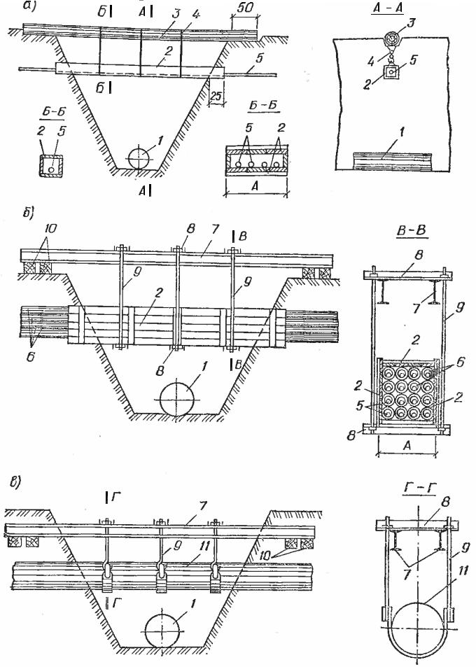
Rice. 1.14. Suspension of communications crossing the trench
a - one or more cables;
6 - cable ducts in asbestos-cement pipes;
c - pipeline;
1 - cable pipe;
2 - a box made of boards or panels;
3 - log or timber; 4 — twist pendants;
5 - cable;
b - asbestos-cement cable sewer pipes;
7 - I-beam; 8— crossbars made of channels;
9 - pendants made of round steel;
10 - linings;
11 - pipeline crossing the trench
The depth of the cable trench depends on where it will go.
If the cable is laid under a road along which vehicles are moving, then the depth of the route must be at least 1.25 meters. It is necessary to dig a trench carefully, since there may be engineering systems in the ground that are not marked on the geological foundation diagram; such an incident occurs very often. If the cable route runs in an urban environment, in close proximity to buildings, structures, or at intersections with communications located in the ground, digging is done only by hand.
The depth of the trench should not be less than 70cm; the width of the trench depends on the number of cables that will be laid.
The depth of laying communication cables in soils of categories I-III must be at least 0.8 m, and in rocky soils - at least 0.5 m in the absence of an alluvial soil layer and 0.7 m in its presence. In populated areas, the depth of the cable trench is increased to 1.0-1.2 m. The classification of soils is given in GOST 25100.
When digging a trench by hand, it is dug so that the side walls of the trench have some slope. This makes digging a trench easier and prevents the walls from collapsing.
The width of the trench in the upper part will depend on the angle of repose and depth; when laying one or two cables, it is taken equal to 0.3 to 0.45 m along the bottom and, accordingly, 0.4-0.5 m at the top of the trench.

Trenches up to 1 m deep in non-falling soils can be dug without slopes.
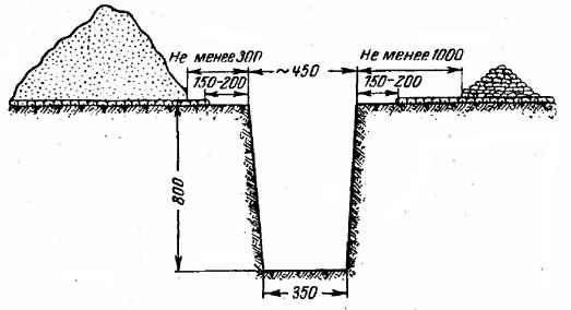
Before digging a trench, foreign objects, temporary structures, construction waste, stones, asphalt coatings are removed from the intended route, and the area is also graded. The asphalt covering is cut with chisels (not crowbars) along the width of the trench. If the pavement is paved with cobblestones, it is excavated on each side 150-200 mm wider than the trench to prevent stones from falling into the trench, which could cause injury to workers or damage the cable laid in the trench.
To allow workers to freely pass along the edge of the trench when excavating soil, the soil thrown out of the trench is placed on one side of the trench at a distance of at least 0.3 m from its edge, and asphalt, cobblestone and other materials are placed on the other side at a distance of 1 m.
When digging a trench, make sure that road signs, green spaces, etc. are not covered.
The bottom of the trench is leveled and cleared of stones and rubble, and before rolling out and laying the cable in stony and rocky soils, it is covered with a layer of sand or loosened soil up to 10 cm thick. This layer is called the “lower bed”. The arrangement of a bedding (pillow) of fine earth (sand) without stones is carried out along the entire length of the trench. To do this, fine earth or sand must be prepared along the entire trench for backfilling the trench. In soft soils, beds can be omitted and the pipes are laid on the leveled soil of the trench bottom.
When digging trenches, it is necessary to ensure that the size of the area to be torn (especially in cities and towns) allows the work to be completed during the working day.
Fencing work areas
During work, the trench running along city streets and driveways is fenced along its entire length. Warning notices and signs are installed on the fences, and special lighting is installed at night and in the evening. The fences also indicate the name and telephone number of the organization performing the work. Fences are installed from the axis of the nearest tram track rail at a distance of 0.6 m, and from the railway tracks 2-2.5 m. In case of openings that require the closure of the passage, the detour direction must be clearly indicated. In places where pedestrians move, the trench is covered with temporary bridges 1 m wide made of durable boards with enclosing railings 1 m high.

Excavation work sites in urban areas should be fenced with slingshots on portable stands, and, if necessary for production purposes or at the request of the territorial administration, with inventory panels or a solid fence. By agreement with the owner of the work site, warning plastic tapes can be used.
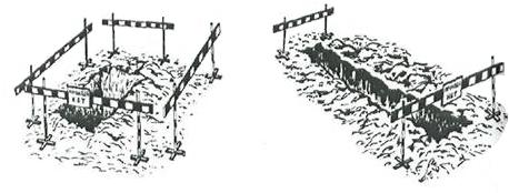
a) fencing the pit and trench

b) fencing a trench dug on the sidewalk
If it is necessary to carry out excavation work on the roadway, the organization carrying out this work must agree with the local traffic police authorities on a scheme for fencing the work site and placing road signs, indicating the types of work and the timing of their completion. The work site, which impedes the movement of traffic, must be fenced off during the day with “quiet movement” signs, and at nightfall and in thick fog - with a red light signal. Light signals are installed at the ends of the trenches.
To ensure normal passage of vehicles and pedestrians when digging up streets, roads and driveways over trenches, transport bridges and pedestrian bridges with railings must be installed. Transport bridges must be designed for the passage of trackless vehicles across the street with an axle load of 10 tons, and when entering courtyards - 7 tons.
The pedestrian inventory bridge must have dimensions: width of at least 0.75 m, height with railings - 1.0 m.
The length of bridges and bridges should cover the trench beyond the natural slope so that when they are used, collapse of the walls does not occur.
Trenches and pits under transport bridges must be secured with spacers.

a) Transport bridge
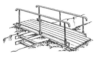
b) Pedestrian bridge
The work site under the tram tracks must be fenced with special fences and signals installed at a distance specified by the safety regulations for this work.
Before starting work, it is necessary to determine the places for vehicles to pass through the highway and the places for pedestrians to move in order to prepare in advance the required number of fences, signal signs and bridges.
If a trench crosses a passage, then first they tear off one side of the passage, lay pipes and fill the trench, and then do the same on the other side of the passage, which allows not to interrupt street traffic.
Opening and restoration of road and street surfaces
Opening of street covers is carried out in an area determined by the size of the trenches, taking into account the norms for additional opening of covers given in the following table.
Standards for additional opening of street covers:
When carrying out work in parks and squares, the top vegetation cover is considered as street cover.
The materials obtained from the opening of street covers, as well as other upper layers of soil, in order to avoid backfilling and clogging with soil removed from the trench, should be placed at a distance of at least 1 m from the edge of the trench on the side opposite to the soil dump.
Temporary paving of trenches on the roadway must be carried out by the construction organization performing the excavation work immediately after its completion. The final restoration of street surfaces is carried out by specialized organizations under contracts with construction organizations.
Laying pipes in trenches

In cases where it is necessary to protect cables from mechanical damage, from the effects of aggressive soils and stray currents, they must be laid in pipes. For this purpose, steel, cast iron, asbestos-cement, ceramic and plastic pipes are used. The pipe material is determined in the project. It is allowed to replace some types of pipes with others, but this must be specified in the project.
Pipes must meet the following requirements:
- their inner surface must be smooth;
- pipe ends with inside must be rounded with a radius of at least 5 mm and have no protrusions, kinks, or burrs;
- pipe connections must be strictly aligned;
- the ends of the pipes at the entrance (exit) to the tunnels, the channels must be sealed flush with the internal surfaces of the walls.
Pipes must be laid with a slight slope of at least 0.2% (3-4 mm per 1 linear meter of pipeline) to drain condensate or water that may enter the pipeline. In areas with sufficient natural slope, the pipeline can be buried evenly along the entire length of the span. During pipeline laying, the set slope value must be monitored by a special rod with a plumb line or an inclinometer.
The pipeline must also be straight horizontally. Deviation from a straight line is allowed no more than 1 cm per 1 m of pipe. To lay the pipes straight, it is recommended to stretch a cord along the bottom of the trench on pegs and lay the pipes along it. Each pipe being laid must touch the cord with its side surface, without pulling it to the side. In some cases provided for by the project, and when unaccounted for obstacles are identified, some deviation of the route from a straight line along a smooth curve is allowed at the rate of no more than 1 cm per 1 m of pipeline length
When forming pipes into blocks, the clear distance between the pipes vertically and horizontally must be at least 10 cm. In this regard, the lower pipes of the block must be laid to a greater depth so that the upper pipes of the block are located at a depth of 0.7 from the planning mark m.
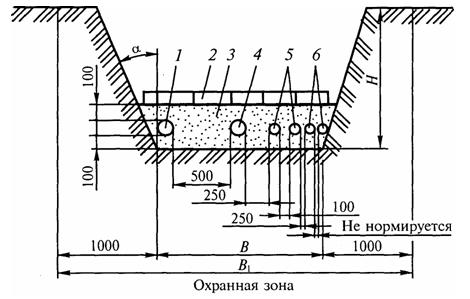
Rice. 2. Laying pipes in a trench:
1 - communication cable; 2 — brick for protection from mechanical damage; 3 - soft soil for backfilling; 4 - cables up to 35 kV; 5 - cables up to 10 kV; 6 - control cables
The width of the trench depends on the number of cables that will be laid. For ease of installation of couplings, there must be extensions of the trench (pit). The depth of the pit is made 10 cm deeper than the bottom of the trench.
In the event of a forced suspension of work in the middle part of the pipeline span, the channels must be temporarily closed with plugs, and the trench protected with earthen rollers to protect it from rain and melt water.
Methods for sealing joints when connecting pipes
Before joining the pipes, the inner and outer surfaces of the channels must be cleaned of dirt and their ends brought together tightly. If a discrepancy in internal and external diameters is detected due to poor quality sorting, the pipe is replaced.
Pipe joining can be done in various ways.
When connecting asbestos-cement pipes, three methods of sealing joints are used:
- using a cuff made of sheet steel,
- using a polyethylene coupling,
- using asbestos-cement couplings.
To seal the joints of asbestos-cement pipes in the first way, it is necessary to deliver grade 50 cement mortar (in a volume that can be used before it dries) and sand to the trench.
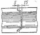
The pipes laid at the bottom of the trenches are aligned end to end. Under the joints of the ends, stepping back a little from them, pour soft soil into a mound, which is compacted with light blows of the ends. The junction of the two ends is wrapped with waterproofing tape to prevent moisture from entering the pipeline. A 60 mm wide sheet steel cuff is placed on the waterproofing tape (bandage), which has a tongue on one side and three slots on the other. Depending on the outer diameter of the pipe, the tongue is inserted into one of the slots, tightened with pliers and bent in the opposite direction (Fig. 3).
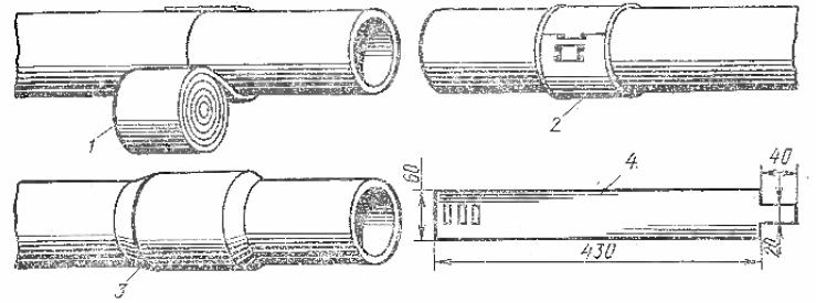
Rice. 3. Joining asbestos-cement pipes using a metal cuff:
1 - wrapping the joint with bitumen tape, 2 - covering the joint with a metal cuff, 5 - coating the joint with cement mortar, 4 - metal cuff
The width of the applied waterproofing tape should be 20 mm greater than the width of the metal cuff. Then the entire joint is coated with cement-sand mortar grade 50.
To join asbestos-cement pipes using the second method, polyethylene couplings with an internal diameter matching the size of the pipe are used (Fig. 4).
Rice. 4. Joining pipes with polyethylene couplings:
1 - polyethylene coupling, 2 - pushing the coupling onto the end of the pipe, 3 - completed joint of two pipes
After laying the pipes in the trench, their ends to the width of the coupling are wiped with a rag. It is best to put on the coupling when it is heated; to do this, immerse it in water heated to a boil and keep it there for 10 - 15 minutes. Then the heated coupling is removed from the tank with a weeding hook, shaken off and, using a screwdriver, pushed onto the end of the first pipe to the protrusion in the middle of the cuff, and then from the other side to the end of the second pipe until the protrusion. After the cuff cools, it narrows and fits tightly around the pipe connection. Since plastic is hot water becomes soft, the muff is very easy to put on, you just have to do everything quickly, without letting it cool down.
If there is a high water level in the trench, then waterproof the joint using a bitumen compound. The inner surface of the coupling from one side to the partition is coated with a bitumen compound and pushed onto the end of the pipe. The end of the second pipe, the width of the coupling up to the partition, is coated with a bitumen compound and inserted into the coupling until it is joined. Sealing the joint is performed in the same way as described earlier.
In some cases, the joints of asbestos-cement pipes are sealed using asbestos-cement couplings, the inner diameter of which is larger than the outer diameter of the pipe. The gap between the pipe and the coupling is clogged with resin tow and sealed with cement mortar or bitumen mastic.
Concrete pipes are connected to each other by inserting the protrusion of one pipe into the socket of another (Fig. 5). A belt of grade 50 cement mortar is placed around the joint. When sealing joints between asbestos-cement and concrete pipes, coating with cement mortar must be done not only on top, but also on the bottom of the pipeline in order to avoid breaking the tightness and deteriorating the strength of the pipeline. For better adhesion of the cement mortar to the pipes, their joints are moistened with water before sealing.
Rice. 5. Joining concrete pipes
Preparing channels for cable laying
Cases often arise when, as a result of groundwater penetrating into a canal, the canals in some places become filled with sand, clay, silt, etc., and the canals need to be cleaned. For cleaning, you should use special steel scoops screwed onto the end of the head stick. By striking the pointed edge of the scoop, the debris is loosened and the scoop filled with it is removed from the canal. The scoop picks up dirt, then it is pulled back, cleaned and pushed back into the channel. The operations are repeated until the sticks pass freely through the channel. Remaining dirt is removed with a steel brush.
Rice. 6.- Scoop for cleaning clogged channels
If cleaning the channels does not give positive results, then this section of the sewer should be opened and repaired. If necessary, inserts are made from sections of new solid or vertically cut pipes.
The serviceability of the pipeline cable channels is checked by pulling a test cylinder through each channel. To do this, a test cylinder is connected with a carabiner to a metal brush and pulled through the channel in order to level and smooth the walls of the channels at the pipe junctions and clean the pipe cavity from debris. At the ends of the test cylinder and brush there are ears, to which a cable is tied on both sides, so that if the cylinder stops, it can be pulled back if the channel is very clogged.

Rice. 7. Test cylinder

Rice. 8.- Brush for cleaning the channel
The cable pipeline is checked before putting it into operation. After checking the serviceability of all channels, in order to avoid clogging and penetration of gases, plastic plugs are installed at the ends of the laid section, which prevent sand, stones and other debris from entering the pipe, which can damage the cable during its installation. Instead of installing a plug, the ends of the pipe can simply be foamed with foam.
The further electrical installation of the cable into the laid pipes depends on how you prepared the cable route and laid the pipes. If you have not compacted the sand well or have joined the pipes poorly, laying the cable will be very problematic, since when pulling the cable into the pipes, its passage may be difficult and will lead to cuts to the insulation
cable.
Download recommendations for the use of asbestos-cement pipes - To read hidden text you need to log in or register.
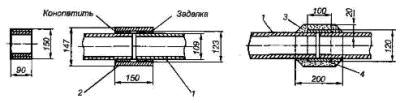
Transporting the cable and preparing it for installation
Properly organized transportation of cables guarantees their safety, and therefore the longevity of the cable lines.
Within storage areas, drums are rolled (over a distance of no more than 100 m) manually, with both ends of the cable securely attached to the drum.
The cable drums are rolled in the direction of cable winding, indicated by the arrow on the drum. Violation of this rule causes loosening of the cable winding on the drum neck and unraveling of the turns, and consequently, their pinching or jamming during rolling.
Delivery of cables and materials (pipes, blocks, etc.) to the work site is usually carried out before the start of work. When transporting or moving cable drums, precautions must be taken to prevent damage to the drum and cable.
Before transportation and installation, drums with cable are subjected to inspection, which begins with an external inspection, the integrity of the drum casing, the bolts holding the drum together, the sealing of the cable ends and the integrity of the metal bushings (at the hole) on the drum cheeks, the factory markings on the outside of the drum cheeks and the passport are checked. cable, sealing cable ends. The inspection results are documented in a report, which is subsequently attached to the as-built documentation of the cable line.
Cables that have not passed the entrance inspection are not subject to installation.
To avoid possible damage to the cable, drums with cables must not be dropped from vehicles, cable trolleys, or conveyors.
It is recommended to store them under a canopy. It is also possible to store the cable outdoors (for up to 1 year) in boarded drums. Cables with plastic insulation without an outer covering in unwired drums should not be stored outdoors. They should be stored with the ends hermetically sealed.
To protect the bottom of the drum from possible flooding during rains, the drums are placed on wooden supports.
Transportation, unloading and movement of cable drums is carried out only in a vertical position.
Testing and measuring cables before laying and installation
Before laying the cable, the insulation resistance of the cores is measured, and for communication cables, the insulation resistance is measured and the cores are checked for breaks and their connection with each other and with the metal sheath, since during transportation and reloading of the cable to the site, the cable insulation may already be damaged, and you will carry out electrical installation of the damaged cable into the pipes, and then you will have to look for the location of the cable damage.
To check the wires for breaks and for their communication with each other and with the metal sheath, both ends of the cable on the drum are freed at a length of 80-300 mm from protective coatings and the metal sheath. Then the insulation is removed from all the cores of one end of the cable to a length of 1.5-3 cm, the stripped cores are connected to each other and to the metal sheath using copper wire. The cores of the second end of the cable are cut into a so-called pyramid, which is obtained as a result of the fact that the cores of each subsequent layer are cut 15-20 mm shorter than the cores of the previous one.
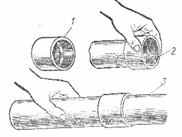
When checking the cores for communication with each other and with the cable sheath, one pole of the battery with a voltage of 3.0-4.5 V is connected to the cable sheath (Fig. 1, a), and on the other - through a telephone 3 in series with each of the cable cores, first disconnecting it from the common bundle for the duration of testing. If the core being tested has a connection with any other core or with a metal sheath, then a click is heard in the telephone under the influence of battery current according to the scheme: battery pole, sheath 2 of the cable, the core being tested, the telephone and the other pole of the battery.
To test the cores for a break, all the cores are connected to the sheath and the test is performed from the side of the pyramid. When you touch the tested core of the free end of the wire coming from the telephone, a click should again be heard in the latter. If a click does not appear on the phone, then the tested wire is broken.
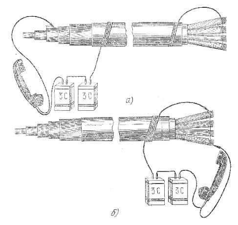
Rice. 9. Scheme for checking the cable for open circuit (a) and message (b)
When testing the wires for a break and a message, it should be borne in mind that with a long cable length, a click in the telephone (weaker) can be obtained due to a noticeable electrical capacitance between the wires and between the wires and the sheath. Therefore, if the cable is long, it is advisable to replace the telephone with some other device (ammeter, voltmeter).
Detected faulty wires are checked a second time, and then separated from the bundle and bandaged. A list of all damaged cores is made, indicating the number of the core pair, the layer in which it is located, and the nature of the damage.
Electrical tests of cables in a plastic sheath are performed in the same way, only in the circuit, instead of a metal sheath, a bare copper core is used as the “ground”.
To control the insulation of cable cores, its resistance is measured using cable instruments or megohmmeters. The obtained data is compared with the standard insulation resistance for a particular cable at a temperature of 20ºC. The insulation resistance of the measured cable is considered satisfactory if it is equal to or greater than the standard one.
Measuring the insulation resistance of the cores and testing them for breakage in signal and control cables is carried out using a megger.
Cable cutting for measurements using a megger is carried out in the same way as when measuring the connection of the cores with each other and the breakage of the cores. When measuring the conductor insulation, one conductor connected to terminal L of the megohmmeter is connected to the conductor under test, and the other conductor connects terminal 3 to the metal sheath or to the remaining conductors connected to each other (for cables with a plastic sheath). By rotating the megger handle at a frequency of about 130 rpm, the value of the core insulation resistance is read off its scale. Depending on the type of megger, it can measure insulation resistance up to 500-1000 MOhm. When testing a wire for a break with a megger, if the wire being tested does not have a break, then when the megger handle is rotated, the needle of its instrument will remain at zero. If there is a break, the arrow will deviate to the left, indicating the value of high resistance, which will indicate the presence of a wire break.
At the end of the electrical tests, the cable cores are cut off and the metal sheath of both ends of the cable is sealed on the drum; the ends of cables with a non-metallic sheath are carefully insulated using PVC tape or another method to prevent moisture from entering the cable.
When loading drums, as well as when rolling them on the ground, you must ensure that the direction of rotation of the drum coincides with the direction of the arrow on the drum cheek.
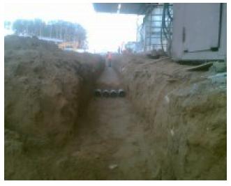
Laying cables in the ground
High quality, stable and reliable operation of the cable lines being constructed can be ensured provided that the technology for their installation is followed.
All electrical installation work on laying cables in a trench must be carried out in accordance with the PUE and PTEEP, since compliance with rules and regulations is the key to trouble-free operation of the power system, electrical wiring, electrical installations and electrical equipment.
Before the laying of cable lines begins, construction work on the construction of routes must be completely completed. For example, before laying cables in the ground, the construction organization completely finishes digging trenches, installing inputs and intersections.
Pulling must be carried out with precautions so as not to damage the cable sheath on the edge of the pipe (the edges must be pre-rounded and not have sharp edges or burrs).
The further electrical installation of the cable into the laid pipes depends on how you prepared the cable route and laid the pipes. If you have not compacted the sand well or have joined the pipes poorly, laying the cable will be very problematic, since when pulling the cable into the pipes, its passage may be difficult and will lead to cuts in the cable insulation.
To carry out work on the construction of cable lines, the installation organization is provided with technical documentation, including a detailed design with a cable route plan and the necessary sections. In plans and drawings of longitudinal route profiles, all intersections of the designed cable line with other underground structures are indicated, regardless of their depth. For complex transitions, special drawings are made or links to standard albums are provided.
The installation organization is also given construction drawings of cable structures indicating all embedded parts. Particularly important documents are the cable log, specifications for cables, couplings, materials, as well as estimates.
The projects are transferred to the installation organization with a stamp “for production”, agreed with the city architectural services, construction departments, land users, the energy system and all organizations whose underground communications are located in the area of the cable lines being designed.
For difficult installation conditions, the work execution plan (WPP) is carried out by the design organization, and for normal conditions - by the installation organization. A more detailed list of design documentation required for the work is indicated in the specialized literature.
When laying cables, a number of technological operations can be distinguished, over which special control is established in order to improve the quality of work and increase the reliability of operation of the installed cable lines.
Most often, damage to cables occurs when their laying technology is violated:
- if the distances between parallel laid cables, between cables and underground structures are not observed;
- non-compliance with the depth of their placement;
- unwinding cables from drums, pulling cables with a force exceeding permissible loads;
- in case of unacceptable bends and twists of cables; low ambient temperatures.
When laying several cables in parallel, the minimum distances established between them are observed according to the conditions of mutual permissible heating or possible damage to the cables by an arc in the event of a short circuit on one of these cables.
Laying cables to a shallow depth increases the possibility of their mechanical damage during various excavation works near cable lines. When unrolling cables from drums, they may be damaged as a result of tightly packed turns sticking to each other. In this case, the rapid rotation of the drums leads to jerks and breaks in the cables. Therefore, cable unwinding is carried out at a minimum speed, using various devices to brake the rotating drums. Damage can occur due to sinking turns when the cable is wound incorrectly onto a drum (usually when rewinding the cable onto inventory drums at cable sites) or when the rules for re-rolling the drums are violated. In this case, the coil coming off the drum is pinched by adjacent coils. In this case, when unwinding the cable, the drum is temporarily stopped and the jammed coil is released.
Damage to cables is possible after laying them with unacceptable bending radii and twisting when unwinding manually with loops.
All these operations must exclude violations of installation technology and be carried out under the supervision of experienced foremen or engineers.
When laying cables in a trench along the entire length, a slack is provided in the form of a “snake” to compensate for changes in the length of the cables caused by temperature fluctuations in them during operation. The cable length in this case is 2-3% greater than the length of the trench.
When laying, reserves of the ends of the construction lengths of cables are left near the pits for couplings. Cable reserves are provided for compensators that protect couplings from damage due to soil displacement, as well as from temperature deformation of cables.
Before starting to lay the cable, stones, debris and excess objects are removed from the trench, water is pumped out, etc. After this, the bottom of the trench is leveled and a “bed” of sand or fine earth 100 mm thick is made. At the same time, they construct passages through the walls of buildings.
To install the cable in pipes, you need to use a special elastic steel cable, which is used to pull the cable through the pipes.
First, they tighten the cable into the pipe so that it passes through it and comes out on the other side of the cable route for 10 - 15 meters, because with the help of this cable the cable is installed in the pipes.
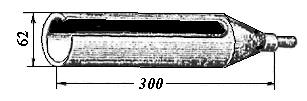
To attach the cable to the cable, you will need a special metal stocking, which is a cylinder woven from thin steel wires and has wefts on one side for fastening it with a rope or cable. When put on, the stocking expands and easily slides over the cable sheath, and when tensioned, it contracts, tightly enveloping the cable.
Metal cable stockings are made of three types: end - for sealing at the end of the cable, through (open at both ends) - for pulling the cable into the well to the required length, and split - for fastening at any point on the cable.
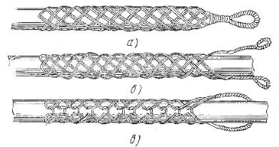
Fig. 10. Cable steel stockings: a) - end, b) - through, c) - split.
To more securely fasten the stocking with the cable, screws are screwed into the stocking pulled over the cable sheath or the end of the stocking is tied with soft wire, and then wrapped with insulating tape over the knitting.
If the cable is laid along an occupied channel, then it is connected to a hemp rope, and the cable stocking along its entire length is wrapped with insulating tape in two or three layers, which protects the cable located in the channel from scratches and chafing. A cable with a capacity of up to 100 pairs is pulled into the sewer by hand.
You must pull the cable by the cable laid in the pipes very carefully so as not to damage the cable sheath. If, when pulling the cable, it hits an obstacle and does not go further, then you should not tie the cable to a car or tractor, since instead of a cable you can pull out bare wires, which will only be suitable for delivery to a non-ferrous metals collection point. If the cable does not go through, then you should carefully pull it back and try to pull it out again.
After you have pulled the cable through the pipes, you must take repeated electrical measurements and measure the insulation resistance electrical circuits both between all cable cores, and between each core and the metal protective sheath of the cable (between each core of a wire or cable in a non-metallic sheath and a pipe, box, tray, structure), to ensure that you do not damage the insulation when laying the cable through the pipes
The insulation resistance of electrical wiring (measuring, control, power, alarm, etc. circuits) is measured with a 1000 V megger. The insulation resistance must be at least 0.5 MOhm. The duration of test voltage application is 1 min. Based on the results of checking the insulation resistance, a report is drawn up. The funnels that you installed on the pipes before laying the cable must be foamed with foam. This must be done so that when digging a trench, sand and stones do not get into the pipes and rodents do not enter the pipes.
Upon completion of cable laying in the trench, the work is checked to ensure compliance with the project requirements. At the same time, an external inspection of the condition of the cable and verification of the correct termination of its ends is carried out. Before filling the trench with soil, permanent landmarks (buildings, fences) are identified and an as-built drawing of the route of the laid cable lines is drawn up. The as-built drawing records the location of the cable line in relation to permanent landmarks in the area, their intersections with roads and underground utilities, marks sections of cables laid in pipes or at a depth of more than 1 m, as well as the locations of connecting and branch couplings. In the absence of local permanent landmarks (in open areas or outside the city), reinforced concrete or metal relay poles are installed on the cable route at a distance of 100-150 m from one another on straight sections of the route, as well as at turns in the route and at connecting couplings.
In addition to the route of the laid cable, other underground and above-ground structures are marked on the plan, for example, water and gas pipelines crossing the cable and running parallel, other cables, roads, ditches, etc., located within a strip of 20-30 m from the cable.
Drawing up an as-built plan facilitates the future operation of the cable and allows you to more accurately and quickly determine the location of its damage.
Tags are attached to laid cables, as well as to all couplings and terminations. Cable labels indicate voltage, brand, cross-section, number or name of the cable. On the labels of couplings and terminations there is a cross-section, cutting date and the name of the cableman.
After laying the cable in the trench, leveling it and tying it to landmarks, sprinkle it on top with a 100 mm thick layer of sand or fine earth. Sprinkling the cable with soil containing construction waste, bricks, slag, etc. is not allowed.
The trenches are filled with soil sequentially in separate layers no more than 0.2 m thick, and each layer is carefully compacted with tampers and watered. Within the carriageway of streets, roads and squares that have an improved surface, trenches are backfilled only with sand to avoid settling of the surface after restoration.
Before backfilling the trench, the laid pipeline must be carefully inspected by a foreman (master) with the participation of a customer representative, and compliance with its technical requirements must be recorded in a hidden work report. Before commissioning, the patency of the channels must be checked with a test cylinder.

