Star news


How to make a charger from a computer power supply. What can be made from a computer power supply
In contact with
Classmates
I have several old computer power supplies lying around in my workshop. At one time they had to be changed often. They lie like trash and it’s a shame to throw them away, I kept thinking about where to use them. It turned out that I was not the only one who was scratching his head over this problem. Well, I found such a project. It turns out quite nice. Emergency flashlight from an old power supply. And if you have a UPS battery lying around, then you already have almost everything you need. The only thing is that if I were the author, I would not fence the circuit with crocodiles for charging the battery from an external charger, but would place it inside the case. Luckily there is enough space. Yes, and I would take an LED lamp. Then even a half-dead old battery will be able to shine for a long time.
Such a flashlight will be very convenient as a car one. You just need to consider the possibility of charging it from the on-board network or from the cigarette lighter. Well, if you don’t have a new car yet, you can look for one.


Do you have a lot of computer spare parts? Do you like to be prepared for emergencies? Are you ready for the zombie apocalypse? Do you understand what I mean when I say the word “Junk Punk”?
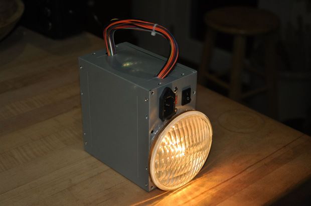
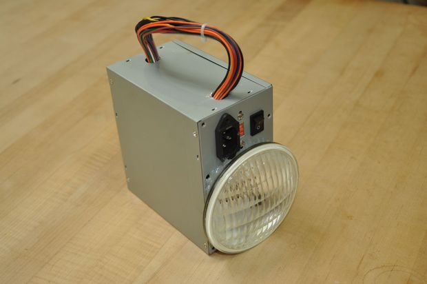
If so, then you should build yourself a recycled computer power supply flashlight!
Using salvaged, reused and reused components, we will build a 12V/11W electric lantern.
This all started recently when I was talking with a friend in the development-to-implementation program in Milwaukee. I was working on a simple wiring project and was chatting and a friend showed me a couple of 5ah lead acid batteries he quenched that were quite good and he gave to anyone who wanted them. This is an excellent size rechargeable battery and the size and shape reminded me of "old fashioned" flashlights that use 9V dry cells. This, and the discussion of zombie movies, I'm wondering - do I have the skills to not only build a portable light from a little more scrap materials, but to build something better than I could buy?
I took this as a challenge and started assembling the powered lantern.
Step 1: Tools and Materials
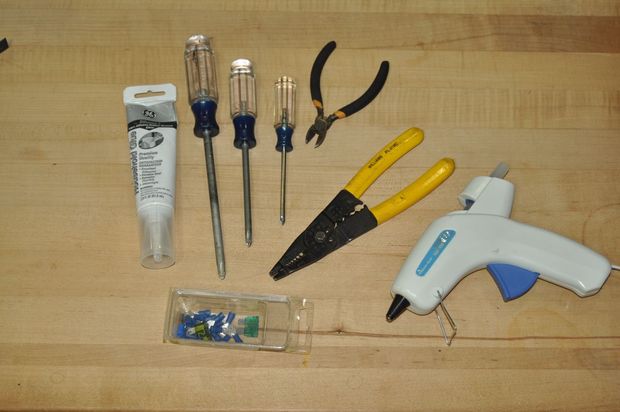
First, let's look at the tools and materials for the project.
Almost all of the materials for this project were recycled, reclaimed or reclaimed. The project was based on the materials I had on hand. If you want to build something like this, you could buy something. Better yet, why don't you create a project using just the materials you have on hand and see what you come up with!
Materials:
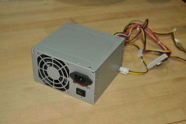
Computer power supply died
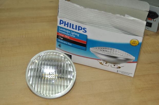
Landscape lighting lamp 12V
Rechargeable battery 12V - 5ah p or other size that is installed inside the power source
Foam or other scrap metal interval
Glue
1/4″ crimp-on terminals with names
Zip connections
Electrical tape or shrink
Charger
You may have noticed that I haven't included any switch or any wire in the materials list. This is because we will be reusing the switch, wiring, and port power already in the power supply.
The tools are simple, something that no reputable DIY interior designer would be without, but when it comes down to it, most can be replaced by a Swiss Army Knife or Multi-Tool.
Tools:
Phillips screwdrivers
Wire Stripper
Wire Tongs
Side cutters
Drills and bits
Multimeter (Optional)
Step 2: Open and Delete Unneeded


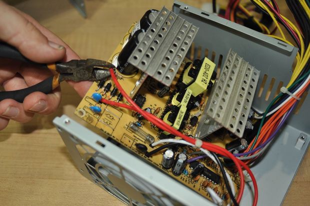
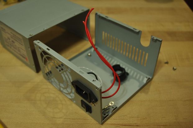

The first step is to open the power supply.
Remove the four Phillips screws that hold the power supply cover in place and remove the cover. The cover is actually 3 sides, or half power. Separate the two parts.
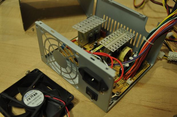
Inside you will see a lot of wires, a circuit board, a fan and switch, and a power port.
Remove the four screws that secure the cooling fan. Disconnect the fan from the board and then set it aside as material for one of your future projects.
Remove the screws holding the circuit board. Find the wires from the switch and power connector, and follow them to where they connect on the board. Trim the wire close to the board to maximize the length of the wire that is permanently attached to the switch and power connector.
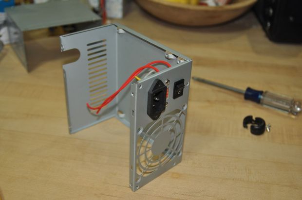
Remove the PCB and set aside.
Now you basically have an empty box with a couple of wires on the switch and power. We will use them as part of the project. You should have enough wire to the battery and light bulb.
Step 3: Battery
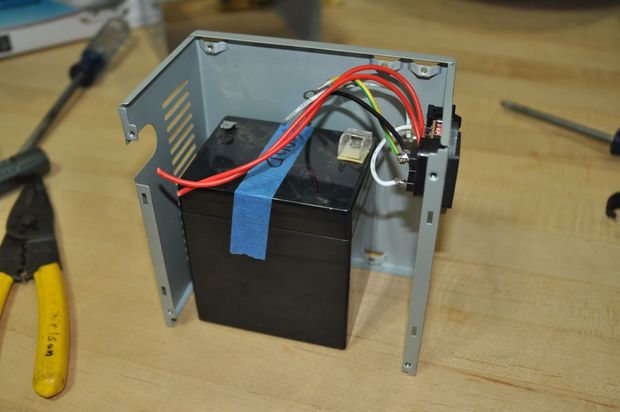
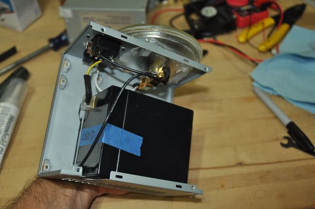
The battery used for the project is a 5 Ah sealed lead acid battery. It fits perfectly inside the power supply case.
The terminals on the battery are not 1/4″ male connectors. It's easy to work with by crimping the spade connectors on the wires and then simply pushing them onto the battery terminal connector.
The battery is marked positive in red and negative in black, and has a plastic protector near the positive terminal to help reduce accidental short circuits.
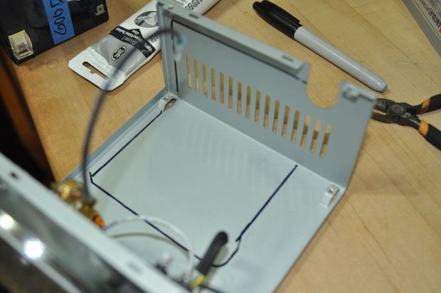
Place the battery in one half of the power supply case to make sure it fits. You can use a pencil or marker to outline it so you know where the lines are to the battery idle.
Step 4: Light
12 volt lamp, 11 watt lamp left over from another project. Usually it can be used in outdoor low voltage landscape lighting, powered by 12V AC transformer.
Something as simple as a light bulb doesn't really care if it's powered by AC or direct current, as long as the voltage is correct. We will be using 12V batteries, so there is no problem converting this ball.
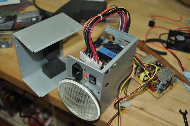
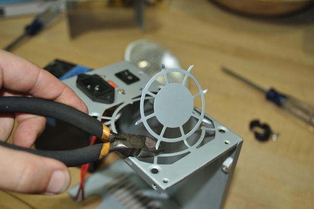
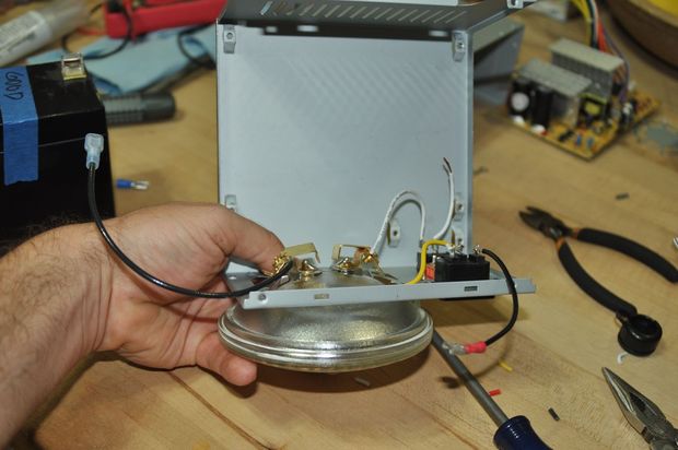
The lamp will take the place of the fan. Keep the ball in the round grill where the fan was. Mark, how much space will the light bulb take up? It's round, and the fan is, so it will fit okay, but not all the way back into the case. (Other size lamps may be flush mounted, or even inside the housing!)
Use side cutters or tin-SNiPs, SNiPs fan tin grille to make the lamps fit. You can also use a Dremel or other cutting tool.
Test fit the light bulb, but don't try to tie it on yet. First, we want the wire to go to the light.
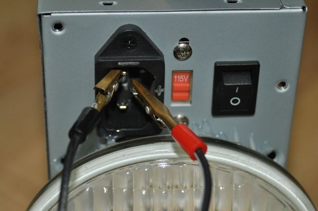
Step 5: Connecting it


The wiring for the light is quite simple. Complete circuit of the entire battery switch to the light bulb and back to the minus battery.
Since this is a rechargeable battery, it would also be nice to add a way to charge the light without having to remove it to access the battery. To do this we will use the power cord port as a place to connect the charger.
First, check the wires, the switch and the power connector will reach the battery and light bulb.
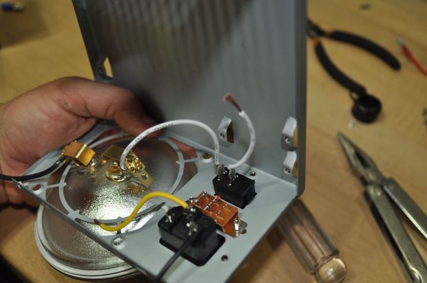
The "115/230" will not use a power switch, so its red wires can be left off. Save them for reuse. This is good, heavy wire, and red is usually used to indicate positive polarity.
Strip and twist together one wire from each power and input switch. Add the female spade shaft and crimp it. This connector goes to the positive terminal of the battery. The other wire from the switch goes to the light bulb.
The other power input wire goes on the opposite side of the ball. That side of the ball also goes to the battery negative. This lamp has "multi-terminals", so you can connect two wires at once to the terminal - one with a thing connector, and one with a bare wire tightened under a screw.
By doing this, power will only go to the light bulb when the switch is on, but the power will always be connected to the two pins on the power input. (Cut off the third wire.) So Charger can be connected to two contacts to charge the battery. Mark with two contacts, observing polarity.
(A note about reusing switches: Switches and other components often have 2 sets of ratings - one for AC and one for DC. The ratings are usually much lower for DC. Use a flashlight to look closely at the side of the switch, and you will see its power. Because it is only a 1 Amp project, this switch will work fine.)
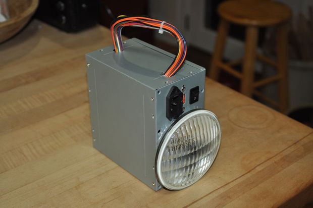
Step 6: Handles

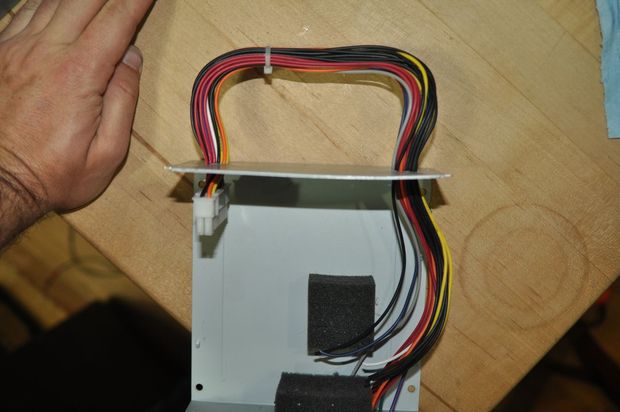

One classic lantern element, located handle, separate from the body of the light.
(Unlike a flashlight, where you just grab the entire flashlight shape around.)
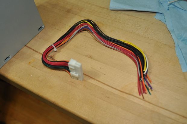
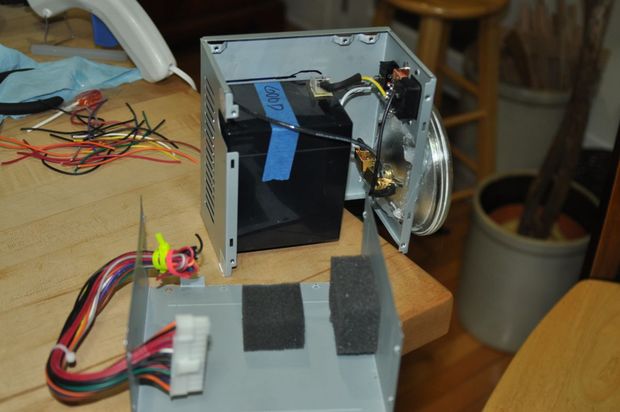
Usually, I like to use some bolts and spacers, and a cross piece of wood or metal, to assemble the handle. However, I didn't have material on hand that seemed to satisfy him - other than the wires still connected to the board, set aside earlier.
These wires were bundled together tightly and the diameter was just about right to be comfortable in the hand. I cut a bunch of wires close to the surface of the board.
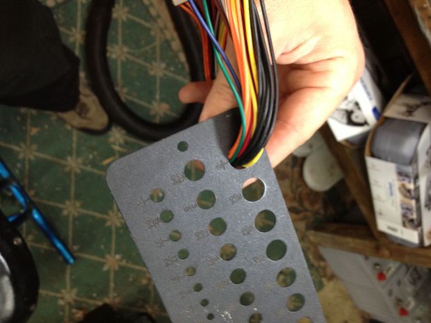
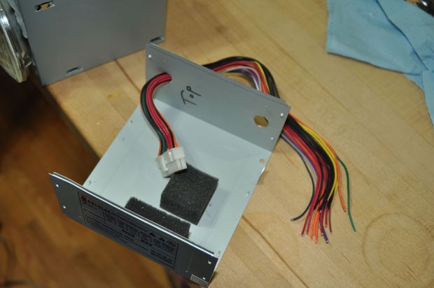
I measured the diameter of the wire harness by feeding it through an index drill. If seemed to fit best in a 1/2″ hole. This meant I was able to drill 1/2″ holes through the sheet metal and then feed the wires right through. I drilled two holes, centered side to side. There were already two stamp marks in the metal about 3/4″ from either end, so I used those as a reference for how far from the edge to drill.
With the holes, I fed the bare end of the wire through the inside of the case, and from the top, and back through the other hole. The board's original computer power connector is too big to fit through the hole, so it acts as a stop.
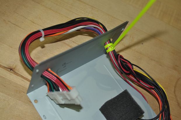
On the other end of the line. I wrapped two zip ties around the wire to tie them in place. Then I put the extra wires there, tied them up again, and cut off the extra wires.
Step 7: Assembly


With the wiring done and the handles done, it all needs to be assembled together.
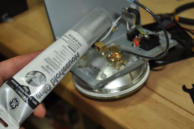
Now is the time to put glue in place of the lamp and battery.
I glued the lantern in place with silicon glue. It works well over a wide temperature range. The lamp will get hot when used, so hot glue would be a bad choice.
On the other hand, the hot glue gun worked great to glue the batteries into the case. I also glued two pieces of foam together with a crowbar to act as a spacer between the battery and the cover.
Once the glue has cooled/drained, reinstall the cover on the body (see foam padding and wire handles) and put the four cover screws back on.
To recharge, I simply hooked up a small charger; I already had two charging pins, which I marked the polarity.
Step 8: Test it!
A diagram of a simple modification of an ATX power supply so that it can be used as a car battery charger. After the rework it will work powerful block power supply with voltage regulation within 0-22 V and current 0-10 A. We will need a regular ATX computer power supply made on a TL494 chip. To start an ATX type power supply that is not connected anywhere, you need to short-circuit the green and black wires for a second.
We solder out the entire rectifier part and everything that is connected to legs 1, 2 and 3 of the TL494 microcircuit. In addition, you need to disconnect pins 15 and 16 from the circuit - this is the second error amplifier that we use for the current stabilization channel. You also need to unsolder the power circuit connecting the output winding of the power transformer from the + power supply of the TL494, it will be powered only by a small “standby” converter, so as not to depend on the output voltage of the power supply (it has 5 V and 12 V outputs). It is better to reconfigure the duty room a little by selecting a voltage divider in the feedback and obtaining a voltage of 20 V for powering the PWM and 9 V for powering the measuring and control circuit. We present schematic diagram improvements:
![]()
We connect the rectifier diodes to the 12-volt taps of the secondary winding of the power transformer. It is better to install more powerful diodes than those that are usually found in a 12-volt circuit. We make choke L1 from a ring from a group stabilization filter. They are different in size in some power supplies, so the winding may differ. I got 12 turns of wire with a diameter of 2 mm. We take choke L2 from the 12 Volt circuit. An output voltage and current measuring amplifier is assembled on the LM358 op-amp chip (LM2904, or any other dual low-voltage op-amp that can operate in single-pole switching and with input voltages from almost 0 V), which will provide control signals to the TL494 PWM. Resistors VR1 and VR2 set the reference voltages. Variable resistor VR1 regulates the output voltage, VR2 regulates the current. Current measuring resistor R7 is 0.05 ohm. We take power for the op-amp from the output of the “standby” 9V power supply of the computer. The load is connected to OUT+ and OUT-. Pointer instruments can be used as a voltmeter and ammeter. If current adjustment is not needed at some point, then simply turn VR2 to maximum. The operation of the stabilizer in the power supply will be like this: if, for example, 12 V 1 A is set, then if the load current is less than 1 A, the voltage will stabilize, if more, then the current. In principle, you can also rewind the output power transformer, the extra windings will be thrown out and you can install a more powerful one. At the same time, I also recommend setting the output transistors to a higher current.

At the output there is a load resistor somewhere around 250 ohm 2 W in parallel with C5. It is needed so that the power supply does not remain without load. The current through it is not taken into account; it is connected before the measuring resistor R7 (shunt). Theoretically, you can get up to 25 volts at a current of 10 A. The device can be charged by both regular 12 V batteries from a car and small lead batteries that are in a UPS.
|
|
 How to connect interior lighting in a closet or sideboard in a living room - an example and description with a step-by-step photo review.
In this article I will tell you how to make a laboratory power supply from an old computer power supply that is very useful for any radio amateur.
You can buy a computer power supply very cheaply at a local flea market or beg it from a friend or acquaintance who has upgraded his PC. Before you start working on a power supply, you should remember that high voltage is dangerous to life and you need to follow safety rules and exercise extreme caution.
The power supply we made will have two outputs with a fixed voltage of 5V and 12V and one output with adjustable voltage 1.24 to 10.27V. The output current depends on the power of the computer power supply used and in my case is about 20A for the 5V output, 9A for the 12V output and about 1.5A for the regulated output.
We will need:
1. Power supply from an old PC (any ATX)
2. LCD voltmeter module
3. Radiator for the microcircuit (any suitable size)
4. LM317 chip (voltage regulator)
5. electrolytic capacitor 1uF
6. Capacitor 0.1 uF
7. LEDs 5mm - 2 pcs.
8. Fan
9. Switch
10. Terminals - 4 pcs.
11. Resistors 220 Ohm 0.5W - 2 pcs.
12. Soldering accessories, 4 M3 screws, washers, 2 self-tapping screws and 4 brass posts 30mm long.
I want to clarify that the list is approximate, everyone can use what they have on hand.
General characteristics of the ATX power supply:
ATX power supplies used in desktop computers are switching power supplies using a PWM controller. Roughly speaking, this means that the circuit is not a classic one, consisting of a transformer, rectifierand voltage stabilizer.Its work includes the following steps:A) The input high voltage is first rectified and filtered.
b) At the next stage constant pressure a sequence of pulses with variable duration or duty cycle (PWM) with a frequency of about 40 kHz is converted.
V) Subsequently, these pulses pass through a ferrite transformer, and the output produces relatively low voltages with a fairly large current. In addition, the transformer provides galvanic isolation between
high-voltage and low-voltage parts of the circuit.
G) Finally, the signal is rectified again, filtered and sent to the output terminals of the power supply. If the current is secondary windings the output voltage increases and the output voltage drops. The PWM controller adjusts the pulse width andThis way the output voltage is stabilized.
The main advantages of such sources are:
- High power in small size
- High efficiency
The term ATX means that the power supply is controlled by the motherboard. To ensure the operation of the control unit and some peripheral devices, even when turned off, a standby voltage of 5V and 3.3V is supplied to the board.
To the disadvantages This may include the presence of pulsed and, in some cases, radio frequency interference. In addition, when operating such power supplies, fan noise is heard.
Power supply power
The electrical characteristics of the power supply are printed on a sticker (see figure) which is usually located on the side of the case. From it you can get the following information: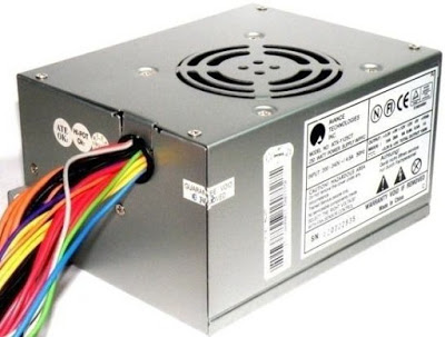
Voltage - Current
3.3V - 15A
5V - 26A
12V - 9A
5 V - 0.5 A
5 Vsb - 1 A
For this project, voltages of 5V and 12V are suitable for us. The maximum current will be 26A and 9A, respectively, which is very good.
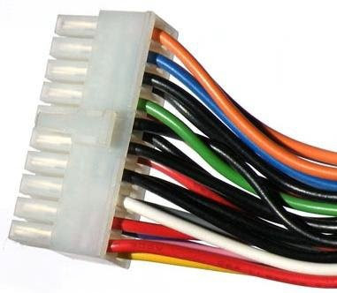
Supply voltages
The output of the PC power supply consists of a wire harness of various colors. The wire color corresponds to the voltage:It is easy to notice that in addition to the connectors with supply voltages +3.3V, +5V, -5V, +12V, -12V and ground, there are three additional connectors: 5VSB, PS_ON and PWR_OK.
5VSB connector used to power the motherboard when the power supply is in standby mode.
PS_ON connector(power on) is used to turn on the power supply from standby mode. When 0V voltage is applied to this connector, the power supply turns on, i.e. to run the power supply without a motherboard, it must be connected tocommon wire (ground).
POWER_OK connector in standby mode it has a state close to zero. After turning on the power supply and generating the required voltage level at all outputs, a voltage of about 5V appears at the POWER_OK connector.
IMPORTANT: In order for the power supply to work without connecting to a computer, you need to connect the green wire to the common wire. The best way to do this is through a switch.
Power supply upgrade
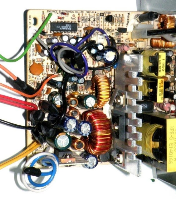
1. Disassembly and cleaning
You need to disassemble and clean the power supply thoroughly. A vacuum cleaner turned on for blowing or a compressor is best suited for this. Great care must be taken because... even after disconnecting the power supply from the network, life-threatening voltages remain on the board.
2. Prepare the wires
We unsolder or bite off all the wires that will not be used. In our case, we will leave two red, two black, two yellow, lilac and green.
If you have a sufficiently powerful soldering iron, solder off the excess wires; if not, cut them off with wire cutters and insulate them with heat shrink.
3. Making the front panel.
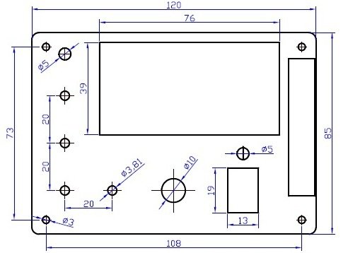
First you need to choose a location to place the front panel. The ideal option would be the side of the power supply from which the wires come out. Then we make a drawing of the front panel in Autocad or another similar program. Using a hacksaw, drill and cutter, we make a front panel from a piece of plexiglass.
4. Rack placement
According to the mounting holes in the drawing of the front panel, we drill similar holes in the power supply housing and screw in the racks that will hold the front panel.
5. Voltage regulation and stabilization
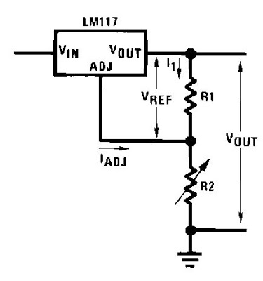
To be able to adjust the output voltage, you need to add a regulator circuit. The famous LM317 chip was chosen due to its ease of inclusion and low cost.LM317 is a three-pin adjustable stabilizer voltage, capable of providing voltage regulation in the range from 1.2V to 37V at a current of up to 1.5A. The wiring of the microcircuit is very simple and consists of two resistors, which are necessary to set the output voltage. Additionally, this microcircuit has overheating and overcurrent protection.
The connection diagram and pinout of the microcircuit are given below:

Resistors R1 and R2 can adjust the output voltage from 1.25V to 37V. That is, in our case, as soon as the voltage reaches 12V, further rotation of resistor R2 will not regulate the voltage. In order for the adjustment to occur over the entire range of rotation of the regulator, it is necessary to calculate the new value of resistor R2. To calculate, you can use the formula recommended by the chip manufacturer:
![]()
Or a simplified form of this expression:
Vout = 1.25(1+R2/R1)
The error is very low, so the second formula can be used.
Taking into account the obtained formula, the following conclusions can be drawn: when the variable resistor is set to minimum value(R2 = 0) the output voltage is 1.25V. As you rotate the resistor knob, the output voltage will increase until it reaches the maximum voltage, which in our case is slightly less than 12V. In other words, our maximum should not exceed 12V.
R2=(Vout-1.25)(R1/1.25)
R2=(12-1.25)(240/1.25)
R2=2064 Ohm
The standard resistor value closest to 2064 ohms is 2 kohms. The resistor values will be as follows:
R1= 240 Ohm, R2= 2 kOhm
This concludes the calculation of the regulator.
6. Regulator assembly
We will assemble the regulator according to the following scheme:
Below is a schematic diagram:
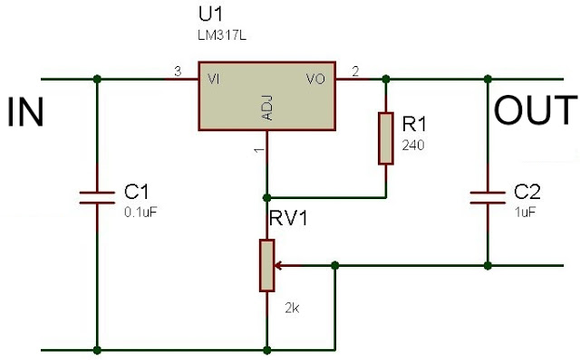
The regulator can be assembled by surface mounting, soldering the parts directly to the pins of the microcircuit and connecting the remaining parts using wires. You can also etch a printed circuit board specifically for this purpose or assemble a circuit on a circuit board. In this project, the circuit was assembled on a circuit board.
You also need to attach the stabilizer chip to a good radiator. If the radiator does not have a hole for a screw, then it is made with a 2.9mm drill, and the thread is cut with the same M3 screw with which the microcircuit will be screwed.
If the heatsink will be screwed directly to the power supply case, then it is necessary to insulate the back of the chip from the heatsink with a piece of mica or silicone. In this case, the screw that secures LM317 must be insulated using a plastic or getinaks washer. If the radiator will not be in contact with the metal case of the power supply, the stabilizer chip must be mounted on thermal paste. In the figure you can see how the radiator is attached with epoxy resin through a plexiglass plate:

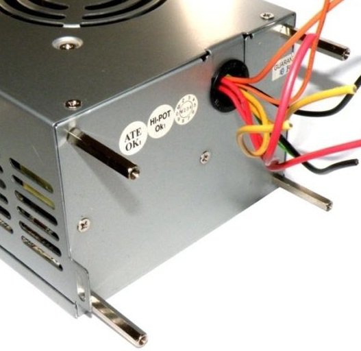
7. Connection
Before soldering, you need to install the LEDs, switch, voltmeter, variable resistor and connectors on the front panel. LEDs fit perfectly into holes drilled with a 5mm drill, although they can additionally be secured with superglue. The switch and voltmeter are held tightly on their own latches in precisely cut holes. The connectors are secured with nuts. Having secured all the parts, you can start soldering the wires in accordance with the following diagram:

To limit the current, a 220 Ohm resistor is soldered in series with each LED. The joints are insulated using heat shrink. The connectors are soldered to the cable directly or through adapter connectors. The wires must be long enough so that the front panel can be removed without problems.
The computer serves us for years, becomes a true family friend, and when it becomes outdated or hopelessly breaks down, it is such a pity to take it to the landfill. But there are parts that can last a long time in everyday life. These include numerous coolers, a processor radiator, and even the case itself. But the most valuable thing is that thanks to decent power with small dimensions, it is an ideal object for all kinds of modernizations. Transforming it is not such a difficult task.
Converting a computer power supply into a conventional voltage source
You need to decide what type of power supply your computer has, AT or ATX. As a rule, this is indicated on the body. Switching power supplies only work under load. But the design of the ATX type power supply allows you to artificially imitate it by shorting the green and black wires. So, by connecting the load (for AT) or closing the necessary terminals (for ATX), you can start the fan. The output appears 5 and 12 Volts. The maximum output current depends on the power of the power supply. At 200 W, at a five-volt output, the current can reach about 20A, at 12V - about 8A. So, without extra costs, you can use a good one with good output characteristics.

Converting a computer power supply into an adjustable voltage source
Having such a power supply at home or at work is quite convenient. Changing a standard block is easy. It is necessary to replace several resistances and remove the inductor. In this case, the voltage can be adjusted from 0 to 20 Volts. Naturally, the currents will remain in their original proportions. If you are satisfied with the maximum voltage of 12V, it is enough to install a thyristor voltage regulator at its output. The regulator circuit is very simple. At the same time, it will help to avoid interference with the inside of the computer unit.
Converting a computer power supply into a car charger
The principle is not much different from regulated source nutrition. It is only advisable to change to more powerful ones. A charger from a computer's power supply has a number of advantages and disadvantages. The advantages primarily include small dimensions and light weight. Transformer chargers are much heavier and more inconvenient to use. The disadvantages are also significant: criticality to short circuits and polarity reversal.
Of course, this criticality is also observed in transformer devices, but when they fail pulse block alternating current with a voltage of 220V tends to the battery. It’s scary to imagine the consequences of this for all devices and people nearby. The use of protection in power supplies solves this problem.
Before using such a charger, take the design of the protection circuit seriously. Moreover, there are a large number of their varieties.
So, don’t rush to throw away spare parts from your old device. Remaking a computer power supply will give it a second life. When working with a power supply, remember that its board is constantly under 220V voltage, and this poses a mortal threat. Follow personal safety rules when working with electric current.
A computer power supply unit (PSU) costs about $30, and a laboratory power supply can cost you $100 or even more! By modifying cheap and often free ATX power supplies, which can be found in any unnecessary computer, you can make a good laboratory power supply yourself with good power, short circuit protection and a stabilized 5V output. On most power supplies, other outputs are not stabilized.
Steps
Take the ATX power supply or disconnect it from the non-working computer.
Disconnect the cable from the power supply and turn off the switch on the rear panel (if there is one). Also, make sure that you are not grounded so that any remaining current will not pass through you.
Remove the screws that secure the power supply to the computer case and pull it out.
Cut the connectors (leave a few inches of wire on the connectors so you can use them for something else later).
Discharge the power supply by leaving it unplugged for several days. Some people connect a resistor (10 ohms) between the black and red wire (power cord on the outside), however this only ensures that low voltage is dumped - which is not dangerous anyway! But high-voltage capacitors can remain charged, which, if the current continues, can be potentially dangerous or even fatal.
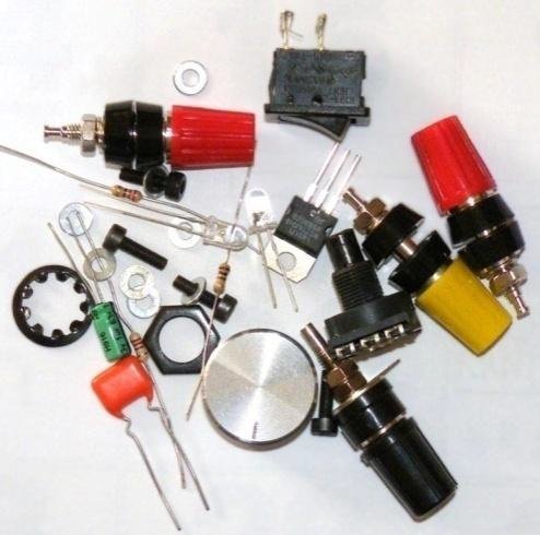
Assemble the necessary parts: screw terminals (terminals), light emitting diode (LED) with a 330 ohm current limiting resistor, a switch (optional), a 10 ohm resistor rated at 10 watts or larger (see Tips), and insulating heat shrink tubing.
Open the PSU by removing the screws connecting the top and bottom of the case.
Separate the wires by color. If you have wires not listed here (brown, etc.), see the Tips section. Wire color code: Red = +5V, Black = Ground (0V), White = -5V, Yellow = +12V, Blue = -12V, Orange = +3.3V, Purple = +5V reserve (not used), Gray = PG (output) and green = ON (must be shorted to (0V) to turn on the power supply).
- Connect one of the red wires to the load resistor, all other red wires to the red terminal;
- Connect one of the black wires to the other terminal of the load resistor, the second black wire to the LED cathode (short leg), the third black wire to the DC-ON switch, all other black wires to the black terminal;
- Connect the white wire to the -5V terminal, yellow to the +12V terminal, blue to the -12V terminal, gray to the resistor (330 Ohms), and solder the second terminal of the resistor to the anode of the LED (its longer leg);
Please note that some PSUs may have either a gray or brown wire as "Power Good" / "Power OK". (Most PSUs have a smaller orange wire that is used to detect +3.3V, and this wire is usually connected in the connector to another orange wire. Make sure this wire is connected to the other orange wires, otherwise your PSU will not work). This wire must be connected to either the orange (+3.3V) or red (+5V) wires for the system to function. If in doubt, try low voltage (+3.3V) first. If the power supply is not ATX or AT, it may have its own color scheme. If your diagram differs from the one shown here in the photo, follow the symbols, not the color specification.
- Connect the green wire to the other output of the switch.
- Make sure that all exposed ends are covered with insulating heat shrink.
- Secure the wires with zip ties or electrical tape, preferably based on color.
Drill holes in the free space of the power supply housing. First, mark the centers of the holes with a nail and a hammer, drill the holes with a drill or Dremel, then enlarge the holes with a reamer until they are the right size for the connection terminals. Also, drill holes for the switch and LED (optional).
Insert the terminals into the corresponding holes and secure with nuts at the back.
Make all necessary connections.
Check the connections by gently pulling the wires. Find bare wires and insulate them to prevent shorting. Use super glue to fix the LED in the hole. Replace the cover.
Connect the cable to the connector on the back of the power supply and plug it into a power outlet. Turn on the main switch on the power supply, if you have installed one. Check if the indicator lights up. You can check the operation of the power supply by connecting a 12 V light bulb to different outputs; You can also check with a voltmeter. Make sure there is no short circuit in any wire. Put the external body of the power supply in order.
- You can use the 12V power supply output to charge your car battery! Be careful: if the battery is very discharged, the short circuit protection of the power supply will trip. In this case, to protect against overload, you can connect a 10 Ohm, 10/20 W load resistor in series with the 12 V output. As soon as the voltage on the battery is close to 12 V (can be checked with a tester), you can remove the resistor and continue charging the battery. This device will help you if the battery is old, or it has died due to attempts to start the car in winter, or you accidentally left the headlights or radio on for a long time, or for some other reason.
- You can also convert the block into a power source for other purposes - but that’s another article.
- If you don't need all nine soldered wires to a terminal (as is the case with ground wires) you can cut them off at the PCB. 1-3 wires will be enough. This means you should also cut off any wires you don't intend to use.
- If you have a signal wire for 3.3 V connected to the 3.3 V pin, then you will not be able to use the 3.3 V voltage as a step-down voltage, for example, from 12 V to 8.7 V. The voltmeter will show 8.7 V, but when connecting a load to 8.7 V, the power supply protection may trip and turn off the entire circuit.
- Some power supplies require the gray and green wires to be connected together to function properly.
- You can add another 3.3V output (for example to power 3V devices) by attaching the orange wire to the terminal (make sure the brown wire remains connected to the orange). Please note that they share power with the 5V output, so the connected load should not exceed the total output power of these two outputs.
- Options: A separate (additional) switch is not required, just connect the green wire to the black one. The power supply will be turned on by the rear switch if there is one. The LED is also optional, you can simply cut and insulate the gray wire.
- If you don't want or don't know how to solder/attach a lot of wires to the connection terminals (for example, ground wires), you can cut them off from the board. It is enough to leave 1-3 wires. Also cut off any wires you don't plan to use.
- You can install the car cigarette lighter into the hole from the power cord. This way you can connect your car equipment to a power source.
- If you are not sure whether the power supply is working properly, check it on your computer first before making any modifications. Has your computer turned on? Has the PSU fan started? You can connect the voltmeter wires to the additional connector (disk drive). The voltmeter should show a value close to 5 V (between the red and black wires). The power supply may not start because there is no load at the output, or the start output (green wire) may not be shorted to ground.
- The +5V line provides +5V power in standby mode (for operating the power button on the motherboard, Wake-on-LAN, etc.). It typically produces up to 500-1000 mA of current even when the main outputs are disabled. Can be used to power an LED indicating the presence of mains voltage.
- From this source you can get voltages of 5 V (+5, zero), 7 V (+12, +5), 10 V (+5, -5), 12 V (+12, zero), 17 V (+5, -12) and 24 V (+12, -12), this should be sufficient for most tasks. Many ATXs with a 24-pin motherboard connector do not have a -5V output. If you need -5V output, look for an ATX unit with a 20-pin, 20+4-pin, or AT connector.
- After finishing the block, clean it and put it in order.
- The power supply fan can be quite loud, because it is designed to cool a fairly loaded power supply and computer components. Of course, you can turn off the fan altogether, but this is a bad idea. If you want everything to be normal, then cut the red wire going to the fan (12 V) and connect it to the red wire coming from PS (5 V). The fan will now spin much slower and quieter, while still providing some cooling. If you need high current strength, then it is better not to do this (do not reduce the fan speed). If you nevertheless decide to do this, then it is under your responsibility; The only thing you can wish for in this case is to watch how quickly the block heats up. You can also replace the standard (factory) fan with a quieter model (soldering may be required).
- To have more space inside the unit, you can mount the fan on the outside of the case.
- You can drill the hole a little larger.
- Some newer PSUs have "voltage sense" wires that must be connected to the appropriate voltage wires for proper operation. The main harness (with 20 wires) should have four red wires and three orange. If there are only two or fewer orange wires, you need to connect a brown wire to them. If you only have three red wires, you need to connect another wire (sometimes pink) to them.
- If you are not afraid to solder, you can replace the 10 W load resistor with a fan. Check polarity - connect red and black wires accordingly.
- The -5V output has been removed from the ATX specification and is no longer available in any ATX box.
- If the power supply does not work and the LED does not light up, see if the fan is spinning. If the fan in the power supply works, then most likely the LED is connected incorrectly (the positive and negative terminals of the LED are mixed up). Open the power supply case and swap the purple and gray wires (make sure the LED is not bypassed).
- The ATX power supply is pulse source power supply (more details at https://ru.wikipedia.org/wiki/Pulse_voltage_stabilizer), it needs some load to work properly. To do this, we use a load resistor, which will generate heat. For good cooling, the resistor must be fixed to the metal wall of the unit’s body (you can also use a separate radiator, making sure it does not short-circuit anything). If some kind of load is connected to the power source whenever it is turned on, then you can do without a resistor. You can also use a 12V illuminated switch as a load, which will act as the load needed to turn on the power.
- For use with appliances with a high starting load (for example, a 12V refrigerator with a capacitor), connect a suitable 12V battery to prevent the power supply from turning off automatically.
Warnings
- Do not touch the wires/tracks leading to the capacitors. Capacitors are cylindrical parts covered with a thin film, with exposed metal at the top and marked with a “+” or “K”. Solid-state capacitors are shorter, slightly thicker and without a film shell. They retain their charge just like batteries, but unlike batteries they can drain very quickly. Even if you have discharged the unit, try not to touch the board with your hands, except in those places where it is necessary. Ground (discharge to ground) everything you touch.
- Make sure the capacitors are discharged. Connect the power cable, turn on the unit (short the green wire to ground), then unplug the power cable and wait until the fan stops spinning.
- If you suspect that the power supply is faulty, do not use it! If it is faulty, the protection circuit may not work. Typically, the protection circuit gradually discharges the high voltage capacitors. But if (for example) the unit is designed for 110 V, but was connected to 240 V, then the protection circuit will most likely fail. In this case, the power supply will most likely not turn off if there is an overload or malfunction.
- When drilling into the metal case, make sure that no metal shavings get inside the power supply. This can cause a short, which in turn can cause fire, overheating, or high voltage surges at the output, which can damage your new power supply that you've worked so hard on.
- High voltage is dangerous and can even be fatal (anything above 30 milliamps/volt can be fatal in a matter of seconds if you touch exposed wires with your hands), at a minimum you will get a painful shock. Before working on the power supply, make sure the power cable is unplugged and the capacitors are discharged as described above. When in doubt, use a multimeter.
- Do not remove the fee unless necessary. Live paths and soldering may remain under high voltage, if you did not leave the power supply for a while to discharge. If you still need to remove the board, use a voltmeter to check the voltage on the large capacitors. When you reinstall the board, make sure there is a plastic spacer underneath it.
- A computer power supply is great for testing or for powering simple electronics (like chargers, soldering irons, etc.), but will never compare to a good lab power supply. If you are going to use the power supply for more than just testing, buy a good laboratory power supply. It’s not for nothing that they are so expensive, there are reasons for that.
- The resulting power supply provides high power output. Possible errors in connections can cause sparking or arcing on low voltage outputs or burn out the circuit you are working with. That's why laboratory blocks power supplies have adjustable current limiters.
- The original article says that you need to be grounded. This is wrong and dangerous. Make sure you are NOT grounded when working on the power source to prevent current from passing through you.

