Star news


Minimum permissible insulation resistance value. Cable insulation resistance
Purpose of measurements
Insulation resistance measurement cable lines, electrical wiring and electrical equipment is carried out in order to identify insulation defects.
1. General Provisions
1.1. Insulation resistance power cable lines up to 1000 V are measured with a megohmmeter at a voltage of 2500 V for 1 minute, while testing is carried out simultaneously increased voltage. The insulation resistance must be at least 0.5 MOhm.
1.2. The insulation resistance of AC electric motors with voltages up to 660 V is measured using a megohmmeter with a voltage of 1000 V. The insulation resistance must be at least 1 MΩ in a cold state, and 0.5 MΩ at a temperature of 60 degrees.
1.3. Measuring the resistance of windings and insulation of machine bands direct current(windings relative to the housing and bands relative to the housing and the windings held by them) together with the circuits and cables connected to them is produced at a rated voltage of up to 500 V with a 500V megohmmeter, and at a rated voltage above 500V with a 1000V megohmmeter. The insulation resistance must be at least 0.5 Mohm.
1.4. The insulation of household stationary electric stoves is measured with a 1000V megohmmeter at least once a year when the stove is hot. The insulation resistance must be at least 1 Mohm.
1.5. The insulation resistance of electrical equipment of cranes or elevators is carried out at least once a year. The insulation resistance must be at least 0.5 MOhm.
1.6. The insulation of power and lighting electrical wiring is measured with a 1000V megohmmeter with the fuse links removed in the area between the removed fuses or behind the last fuses between any wire and the ground, as well as between two wires. When taking measurements in power circuits, electrical receivers must be turned off. When taking measurements in power circuits, electrical receivers, as well as devices, instruments, etc. must be turned off. When measuring insulation resistance in lighting circuits, the lamps must be unscrewed and the sockets, switches and panel boards connected. In lighting circuits from group panels to lamps, it is allowed not to measure insulation resistance if checking the insulation requires a significant amount of work to dismantle the circuit and these circuits are protected by fuses. The condition of such circuits, devices and apparatus must be checked through a thorough external inspection at least once a year. When the neutral is grounded, the inspection is carried out in conjunction with checking the protection operation (measuring the single-phase short-circuit current).
The insulation resistance of electrical wiring in especially damp and hot rooms, in outdoor installations, as well as in rooms with a chemically active environment is measured in full at least once a year. The insulation resistance must be at least 0.5 MOhm.
1.7. Switchgears, switchboards and conductors. The insulation resistance is measured for each section of the switchgear with a 1000V megohmmeter. If possible, it is carried out simultaneously with the testing of electrical installations of power and lighting circuits connected to devices, switchboards or conductors. The insulation resistance must be at least 0.5 MOhm.
1.8. Secondary circuits of control, protection, measurement, automation and telemechanics. It is permissible not to measure insulation resistance if the test requires a significant amount of work to dismantle the circuit and these circuits are protected by fuses or releases with inverse current characteristics. The condition of such circuits, devices and apparatus must be checked through a thorough external inspection at least once a year. When the neutral is grounded, the inspection is carried out in conjunction with checking the protection operation (measurement of short-circuit current).
1.9. Each connection of secondary circuits and power supply circuits of drives of switches and disconnectors.
Insulation resistance is measured using a 1000V megohmmeter with all connected devices (drive coils, controllers, relays, devices, secondary windings current and voltage transformers, etc.). The insulation resistance must be at least 1 MOhm.
1.10. The specific timing of measurements (according to clause 1.6, specified in clause 1.2 of the instructions of the standards) is determined by the person responsible for electrical equipment on the basis of the above standards, departmental or local PPR system in accordance with standard and factory instructions, depending on local conditions and the state of electrical installations.
2. Instruments and measuring instruments
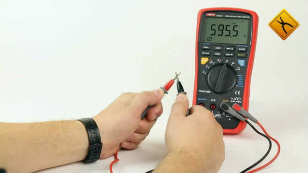
Measurements are carried out with a megohmmeter type E6-24.
3. Qualification and quantitative composition brigades
Work on measuring insulation resistance is carried out by order of a team of at least two people, of whom the work performer must have an electrical safety group of at least the fourth, and a member of the team must have at least the third. Both team members must be qualified to conduct electrical tests.
4. Measurement procedure
4.1. The insulation resistance is measured between all phases and between each phase and zero in sections between switching devices, starting from the power panel and ending with the end consumer.
4.2. The insulation resistance is taken to be the resistance value measured over 1 minute.
5. Test sequence
5.1. Connect the connecting wires to the “Rx” terminals of the megohmmeter
5.2. To measure the insulation resistance between phases A and B (Ra-b), connect one measuring wire to phase A of the measured section, and the other to phase B, press and hold the "Rx" button or use the "capture" mode of the "Rx" button, when The measurement result will appear on the indicator.
5.3. At the end of the measurement, the removal of residual voltage from the object automatically begins, the current value of which is displayed by an intermittent glow until it drops to 40 V.
5.4. To measure the insulation resistance R a - c, disconnect the connecting wire from phase B and connect it to phase C. Measure Ra - c according to clause 5.2.
5.5. Disconnect connecting wire A and connect it to phase B. Measure r in - c according to clause 5.2.
5.6. Disconnect the connecting wire from phase B and connect it to zero. Measure Re - 0 according to clause 5.2.
5.7. Disconnect the connecting wire from phase C and connect it to phase B. Measure rb - 0 according to clause 5.2.
5.8. Disconnect the connecting wire from phase B and connect it to phase A. Measure Ra - 0 according to clause 5.2.
5.9. Disconnect the connecting wires from phase A and zero.
5.10. Carry out measurements according to clauses 5.2 - 5.9 in other areas of the electrical installation.
6. Measures for safe work performance
6.1. Measurement of insulation resistance of electrical installations must be carried out by specially trained electrical laboratory personnel
6.2. The composition of the team when making measurements, see paragraph 3.
6.3. The work performer and team members must have personal certificates of the established form on testing knowledge of safety regulations, and assigned to the electrical safety group with a note for the right to carry out measurements in the column of the certificate for the right to carry out special work.
6.4. The team must undergo electrical safety training, taking into account the specifics of the electrical installation on which they will work. The work contractor must also be instructed on the installation's power supply diagram.
The briefing is documented by an entry in the briefing log with the signatures of the persons being instructed and the person conducting the briefing.
The briefing must be carried out by a person with group 5 from the administrative and technical personnel, or with group 4 from the operational or operational maintenance personnel of the operating organization.
6.5. Preparation of the workplace and permission to work is carried out by operational personnel.
6.6. Connecting a megohmmeter to the circuit being measured and measuring the insulation resistance must be carried out with the voltage turned off in compliance with all labor protection rules when operating electrical installations, i.e. with a poster “Do not turn on” hanging on the wire of the switching device. People are working” and checking the absence of voltage between all phases and each phase and zero. If necessary, measures must be taken to fence off the uninsulated live parts of adjacent electrical installations that are energized and the opposite end of the cable being tested.
7. Registration of measurement results
The measurement results are recorded in the protocol. Based on a comparison of the measurement results with the requirements of clauses 1.3-1.10 of this methodology, a conclusion is made about the compliance of the insulation resistance with the requirements of the PUE and PTEEP. The protocols are compiled into a report, which is approved by the head of the laboratory. The report is accompanied by a defect sheet, which contains all the defects found during the measurement.
8. List of regulatory documentation
8.1. GOST R 50571.16-2007 Electrical installations of buildings. Part 6. Tests.
8.2. Rules technical operation electrical installations of consumers (approved by order No. 5 of January 13, 2003 of the Ministry of Energy Russian Federation, entered into force on July 1, 2003).
8.3. Rules for electrical installations. Sixth edition, revised and expanded, with changes Glavgosenergonadzor of Russia, Moscow, St. Petersburg 2001. Seventh edition: section 1 - chapters 1.1; 1.2; 1.7; 1.9. Moscow 2002; Chapter 1.8. Moscow 2004; section 2 – chapters 2.4; 2.5. Moscow 2003; section 4 – chapters 4.1; 4.2. Moscow 2004; section 6. Moscow 2002; section 7 – chapters 7.1; 7.2 Moscow 2002; 7.5; 7.6; 7.10 Moscow 2002.
8.5. Interindustry rules on labor protection (safety rules) during the operation of electrical installations. POT R M – 016 –2001. RD 153-34.0 – 03.150 – 00.
8.4. Instructions for the use and testing of protective equipment used in electrical installations (Moscow 2004).
8.7. Scope and standards for testing electrical equipment. RD 34.45-51.300-97. Moscow, 2001
8.8. State standard of the Russian Federation GOST R IEC 449-96.
8.9. Rules for the technical operation of consumer electrical installations (approved by order No. 6 of January 13, 2003 of the Ministry of Energy of the Russian Federation, put into effect on July 1, 2003).
9. Standardized values of measured quantities
The measured values of insulation resistance must meet the requirements given in Table 1 Scope and standards for testing electrical equipment. RD 34.45-51.300-97. Moscow, 2001 tab. 2.6.1, in table.2. PUE table 1.8.34., in table 3. PTEEP table 37
Table 1
Test element |
Megger voltage, V | |
|
6. Switchgears 4), switchboards and conductors |
4) The insulation resistance of each section of the switchgear is measured.
|
table 2 |
||
|
Test element |
Megger voltage, V |
Lowest permissible value of insulation resistance, MOhm |
|
1 . DC buses on control panels and in switchgears (with disconnected circuits) 2. Secondary circuits of each connection and power supply circuits for drives of switches and disconnectors 1) . 3. Control, protection, automation and measurement circuits, as well as excitation circuits of DC machines connected to power circuits 4. Secondary circuits and elements when powered from a separate source or through an isolation transformer, designed for an operating voltage of 60 V and below 2) 5. Electrical wiring, including lighting networks 3) 6. Switchgears 4), switchboards and conductors (busbars) | ||
1) The measurement is carried out with all connected devices (drive coils, contactors, starters, circuit breakers, relays, instruments, secondary windings of current and voltage transformers, etc.).
2) Measures must be taken to prevent damage to devices, especially microelectronic and semiconductor components.
3) Insulation resistance is measured between each wire and ground, and between every two wires.
4) The insulation resistance of each section of the switchgear is measured
The test voltage value for relay protection circuits, electrical automation and other secondary circuits with all connected devices (drive coils, automatic machines, magnetic starters, contactors, relays, devices, etc.) is assumed to be 1000 V 1. Lighting networks are tested at the specified voltage in cases where the wiring has a lower insulation level than the norm. In other cases, the test can be carried out with a megohmmeter for a voltage of 2500 V.
The duration of test voltage application is 1 min.
Secondary circuits designed for an operating voltage of 60 V and below, as well as circuits containing devices with microelectronic elements, with a voltage of 1000 V and a frequency of 50 Hz are not tested.
During routine repairs (T), testing with a rectified voltage of 2500 V using a megohmmeter or a special installation is allowed.
|
Table 3 Minimum permissible values of insulation resistance of elements electrical networks voltage up to 1000 V (PTEEP table 37) |
|||
|
Item name |
Megger voltage, V |
Insulation resistance, MOhm |
Note |
|
Electrical products and devices for rated voltage, V: over 50 to 100 over 100 to 380 |
Must comply with manufacturers' instructions, but not less than 0.5 |
When taking measurements, semiconductor devices in products must be shunted |
|
|
Switchgears, boards and conductors |
At least 1 |
Measurements are taken on each section of the switchgear |
|
|
Electrical wiring, including lighting networks |
Not less than 0.5 |
Insulation resistance measurements in particularly hazardous rooms and outdoor installations are carried out once a year. In other cases, measurements are made once every 3 years. When making measurements in power circuits, measures must be taken to prevent damage to devices, especially microelectronic and semiconductor devices. In lighting networks, lamps must be unscrewed, sockets and switches connected |
|
|
Secondary circuits of switchgears, power supply circuits for drives of switches and disconnectors, control circuits, protection circuits, automation, telemechanics, etc. |
At least 1 |
Measurements are made with all connected devices (coils, contactors, starters, switches, relays, instruments, secondary windings of voltage and current transformers) |
|
|
Cranes and elevators |
Not less than 0.5 |
Produced at least once a year |
|
|
Stationary electric stoves |
At least 1 |
Performed when the stove is heated at least once a year |
|
10. Test frequency
1.2. The frequency and standards of measurements are regulated by the standards for testing electrical equipment and devices of consumer electrical installations (Appendix 3 of PTEEP). Insulation resistance measurements are carried out before commissioning, after reconstruction and major repairs of the electrical installation. Insulation resistance measurements in existing electrical installations are carried out in accordance with approved PPR schedules, but at least once a year:
For secondary circuits of relay protection and automation;
For electrical wiring in particularly damp, hot rooms, outdoor installations, as well as their distribution panels;
For household stationary electric stoves.
For hand-held power tools, portable lamps with auxiliary equipment - at least once every 6 months
Electrical installations, devices, secondary circuits, test standards for which are not definedin sections 2-27 (PTEEP), and electrical wiring with voltage up to 1,000 V
K, T, M - are produced within the time limits established by the PPR system.
|
Test name |
Type of test |
Test standards |
Directions |
|
1.Insulation resistance measurement 2. High voltage testing of industrial frequency electrical products with a voltage higher 12V AC and 120V DC, including: 1) insulation of the windings and current-carrying cable of a portable power tool relative to the body and external metal parts |
See table. 37 (add. 3.1) Duration of voltage application (Uapp) – 1 min For power tools with voltages up to 50 V, 550 V is accepted. For power tools with voltages above 50 V and power up to 1 kW - 900 V, with power over 1 kW - 1350 V |
During testing, power tools with a body made of insulating material must have wrapped in metal foil and connected to the ground electrode, the housing and the parts connected to it. |
|
If the insulation resistance is more than 10 MΩ, the high-voltage test can be replaced by measuring the one-minute insulation resistance with a voltage megohmmeter |
|||
|
2) winding insulation step-down transformers 3. Testing with increased voltage of industrial frequency power and secondary circuits with operating voltage above 50V AC, not containing devices with microelectronic elements: 1) insulation of switchgear elements of drives of switches, short circuiters, separators, devices, as well as secondary control circuits, protection, automation, telemechanics, etc. 2) isolation of power and lighting electric postings |
The test voltage should be 1350 V at a rated voltage of the primary winding of the transformer 127-220 V, and 1800 V at a rated voltage of the primary winding 380-440 V Test duration - 1 min. Test voltage - 1,000 V |
The test voltage is applied alternately to each of the windings. In this case, the remaining windings must be connected to grounded case and magnetic core When carrying out tests with a megohmmeter at 2,500 V, it is possible not to carry out measurements with a megohmmeter at Performed if the insulation resistance is below 1 MOhm |
Services are provided by the Official Dealer, ENETRA Technologies. Among the numerous range of electrical equipment offered by our company, the latest development of METZ is transformers with aluminum foil winding TMG21. The new product is produced with a capacity of 630 and 1000 kVA and will replace similar transformers of the 11 series, TMG 11.
Any electrical product is characterized by a number of parameters. For cables, one of the main ones is insulation resistance. There are certain standards that must be taken into account during design and installation, as well as during operation and maintenance of communication routes.
What are the standards for cable insulation resistance? The fact is that there are often discrepancies on this issue. This is caused, according to the author, by several factors.
Firstly, cable is a general concept. This group of products includes samples used for laying power, signal and telephone lines. Cables can be coaxial (radio frequency), control, distribution and general purpose. That is, there are many options for the design of protective shells, differing, among other things, in thickness.
Secondly, a variety of materials are used to make insulation - rubber, plastics, even paper impregnated in a special way. Although in more modern cables the protection is usually complex, that is, combining various dielectric layers.
Thirdly, what kind of insulation resistance are we talking about - the outer shell or the surface coating of the cores?

Fourthly, the specifics of installation and further operation of a particular cable should be taken into account. For example, the route laying method is open or closed. Where it is laid - in the ground, in trays (there are plenty of options). What characterizes the environment - the maximum value and changes in temperature, humidity, aggressiveness, and so on.
Insulation resistance - standards for cables
All values are in MOhm.
Power cables
- High voltage (more than 1,000 V). There are no norms for them. That is, the higher the insulation resistance, the better. It is generally accepted that its value should not be less than 10.
- Low voltage (up to 1,000 V). In fact, we are talking about electrical wiring and secondary circuits of various installations. The minimum limit for the insulation resistance value is 0.5. More detailed information on this issue can be found in the 7th edition of the PUE (Table 1.8.34 and clause 1.8.37).
Control, signal, general purpose cables
This is a fairly large group of products. This includes cables installed for control circuits, automation, power supply of electric drives, connection of protective and distribution devices, and so on. For them, it is considered normal if the insulation resistance is not lower than 1. But this is a generally accepted indicator. The exact meaning, depending on, should be found in its accompanying documentation.
For communication cables, the resistance standards are somewhat different, more “strict”. For city low-speed lines – at least 5, trunk lines – 10 (MOhm/km).
If the cable has an outer sheath made of aluminum coated with PVC, then the resistance standard is higher and equal to 20.
Note. The PUE stipulates that the measurement of insulation resistance is carried out with a megohmmeter with the inductor voltage:
- for cables in circuits not exceeding 500 V – 500;
- up to 1,000 V – 1,000;
- all others – 2,500.
Specialists do not need to explain that all requirements for insulation resistance are indicated in technical specifications, GOST and SNiP for a certain type of work. Its value can be easily found out from the cable passport, and if it is necessary to monitor the condition of the product, make the appropriate measurement. The specifics of this operation are specified in clause 1.8.7. PUE (7th edition).
In everyday life, to assess the degree of wear of the power cable insulation, you can use the following table, which reflects the approximate average standards.
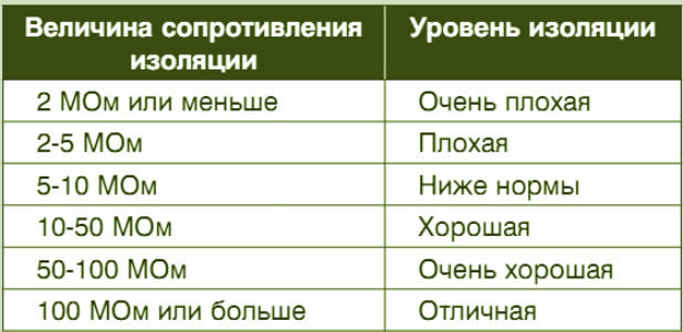
Since a non-professional is not able to take into account all the nuances of the design of the product and its use, this, as a rule, is quite enough to understand whether a given sample is worth laying down or whether it is no longer suitable for use. That is, reject it. Well, if there are certain doubts, then it is a good idea to consult with a specialized specialist.
1. Purpose of measurement .
Measurements are carried out to verify compliance of insulation resistance with established standards.
2. Security measures.
2.1 Technical events.
Before and during measurements, it is necessary to carry out technical measures in accordance with the “Safety Rules” (SHR). When working with a megger, you must be guided by paragraphs B 3.7.17-B 3.7.22 PTB.
2.2 Organizational events.
Measurements with a megohmmeter are allowed to be carried out in installations with voltages above 1000V by two persons, one of whom must have an electrical safety group of at least IV. Work is carried out according to order. In installations with voltages up to 1000V, measurements are performed by two persons, one of whom must have a group of at least III. The work is carried out in the order of current operation with subsequent recording in the operational log.
3. Standardized values .
The frequency of testing and the minimum permissible value of insulation resistance must comply with those specified in the testing standards for electrical equipment and apparatus “Rules for the technical operation of consumer electrical installations.” As a rule, the insulation resistance of BSSN and FSSN systems measured with a 250 V megohmmeter must be at least 0.25 MOhm, power circuits up to 500 V (except for BSSN and FSSN systems) measured with a 500 V megohmmeter must be at least 0.5 MOhm, and secondary circuits - at least 1 MOhm. The insulation resistance of power circuits above 500 V measured with a 1000 V megohmmeter must be at least 1.0 MOhm (GOST R50571.16-99). The insulation resistance of electrical wiring, including lighting networks, measured with a 1000 V megohmmeter must be at least 0.5 MOhm (PTEEP clause 28.1)
4.
Appliances used.
To measure insulation resistance, megohmmeters of the following types are used: MI 3102H (for voltages 100 V, 250 V, 500 V 1000 V and 2500 V) and E6-24 (for voltages 500 V 1000 V and 2500 V). These devices have their own power source - a direct current generator and allow direct reading of readings in megaohms and gigaohms.
5. Measuring the insulation resistance of electrical equipment.
5.1. Insulation resistance measurement power cables and electrical wiring
When measuring insulation resistance, the following must be taken into account:
Measurement of insulation resistance of cables (except for armored cables) with a cross-section of up to 16 mm2 is carried out with a 1000 V megohmmeter, and above 16 mm2 and armored ones - with a 2500 V megohmmeter; The insulation resistance of wires of all sections is measured with a 1000 V megameter.
In this case, it is necessary to make the following measurements:
On 2- and 3-wire lines there are three measurements: L-N, N-PE, L-PE;
On 4-wire lines - 4 measurements: L1-L2L3PEN, L2 - LЗL1PEN, LЗ-L1L2PEN, PEN-L1L2L3, or 6 measurements: L1-L2, L2-L3 ,
L1-L3, L1-PEN, L2-PEN, LЗ-PEN- on 5-wire lines - 5 measurements: L1-L2L3 NPE, L2-L1L3NPE, LЗ-L1L2PE, N-L1L2L3PE, PE-NL1L2L3, or
10 measurements: L1-L2, L2-L3, L1-L3, L1-N, L2-N, L3-N, L1-PE, L2-PE, LZ-PE, N-PE.
It is permissible not to measure insulation resistance in lighting networks in operation if this requires significant work to dismantle the circuit; in this case, at least once a year, visual inspection is required together with checking the reliability of operation of overcurrent protection devices (current determination single-phase faults in accordance with clause 1.7.79 of the PUE).
If electrical wiring in operation has an insulation resistance of less than 0.5 MOhm, then a conclusion about their suitability is made after testing them with alternating current of an industrial frequency voltage of 1 kV in accordance with the recommendations given in this publication.
5.2. Measuring the insulation resistance of power electrical equipment
The insulation resistance value of electrical machines and devices largely depends on temperature. Measurements should be made at an insulation temperature not lower than +5°C, except in cases specified in special instructions. At lower temperatures, the measurement results do not reflect the true insulation performance due to unstable moisture conditions. If there are significant differences between the measurement results at the installation site and the manufacturer's data due to the difference in temperature at which the measurements were taken, these results should be corrected according to the manufacturer's instructions.
The degree of insulation moisture is characterized by an absorption coefficient equal to the ratio of the measured insulation resistance 60 seconds after applying the megohmmeter voltage (R60) to the measured insulation resistance after 15 seconds (R15),
Cubs = R60/ R15
When measuring the insulation resistance of power transformers, megohmmeters with an output voltage of 2500 V are used.
Measurements are taken between each winding and the housing and between the windings of the transformer.
In this case, R60 must be adjusted to the results of factory tests depending on the temperature difference at which the tests were carried out.
The value of the absorption coefficient should differ (downwards) from the factory data by no more than 20%, and its value should not be lower than 1.3 at a temperature of 10-30°C. If these conditions are not met, the transformer must be dried.
Minimum permissible resistance insulation for installations in operation are given in Appendix 3 of PTEEP, Table 9, and for installations being commissioned - in Chapter. 1.8. PUE, table 8. The insulation resistance of manual electrical machines is measured relative to the body and external metal parts with the switch on.
The body of the power tool and the parts connected to it, made of dielectric material, must be wrapped in metal foil connected to the ground loop for the duration of the test.
If the insulation resistance is at least 10 MΩ, then testing the insulation with increased voltage can be replaced by measuring its resistance with a megohmmeter with an output voltage of 2500 V for 1 minute.
For portable transformers, the insulation resistance between all windings, as well as between the windings and the housing, is measured. When measuring the insulation resistance of the primary winding, the secondary must be closed and connected to the housing.
The insulation resistance of circuit breakers and RCDs is produced:
1. Between each pole terminal and the opposite pole terminals connected to each other when the switch or RCD is open.
2. Between each unlike pole and the remaining poles connected to each other when the switch or RCD is closed.
3. Between all interconnected poles and the body, wrapped in metal foil.
At the same time, for circuit breakers for household and similar purposes (GOST R50345-99) and RCDs when measured according to paragraphs. 1, 2, the insulation resistance must be at least 2 MΩ, according to paragraph 3 - at least 5 MΩ.
For other circuit breakers (GOST R50030.2-99), in all cases the insulation resistance must be at least 0.5 MOhm.
6. Measuring insulation resistance with the E6-24 device
6.1.
The appearance of the device is shown in Figure 1
Picture 1
1, 2, 3 - sockets for connecting cables
4 - indicator
5 - indicator of units of measurement (from top to bottom, respectively:
Voltage, V
Gom Resistance
Resistance Mom
6 - test voltage indicator (from left to right, respectively: 500V, 1000V, 2500V)
7 - battery charge indicator
8 - switch on and off the device state
9 - test voltage setting button
10 - button for outputting results from memory
11 - resistance measurement button
6.2.
Before starting measurements, you must make sure that there is no voltage on the object being tested, thoroughly clean the insulation near the measurement point from dust and dirt, and for 2-3 minutes. Ground the object to remove possible residual charges from it. After completing the measurements, the test object must be discharged by short-term grounding.
To connect a megohmmeter to the device or line under test, separate wires with a high insulation resistance (usually at least 100 MOhm) should be used.
Before use, the megohmmeter should be subjected to a control test, which consists of checking the readings on the scale with open and short-circuited wires. In the first case, the arrow should be at the “infinity” scale mark, in the second - at zero.
To ensure that the megohmmeter readings are not affected by leakage currents on the insulation surface, especially when taking measurements in damp weather, the megohmmeter is connected to the object being measured using the E clamp (screen) of the megohmmeter. With this connection, leakage currents along the insulation surface are diverted to the ground, bypassing the device winding.
The insulation resistance value is largely dependent on temperature. Insulation resistance should be measured at an insulation temperature of at least +5°C, except in cases specified in special instructions. At lower temperatures, the measurement results do not reflect the true insulation performance due to unstable moisture conditions.
When measuring insulation resistance relative to ground using a megohmmeter, it is recommended to connect the “+” terminal to the current-carrying part of the installation under test, and the “-” (ground) terminal to its body. When measuring insulation resistance electrical circuits, Not
connected to ground, the megohmmeter terminals can be connected in any way.
The use of clamp “E” (screen) significantly increases the measurement accuracy at high insulation resistances, eliminates the influence of surface leakage currents and thus does not distort the measurement results.
To connect a megohmmeter to the object being tested, it is necessary to have flexible wires with insulated handles and restrictive rings at the ends. The length of the wires should be as short as possible.
Before starting the measurement, it is necessary to measure the insulation resistance of the connecting wires. The value of this resistance must be no less than the upper limit of measurement of the megohmmeter.
The insulation resistance is taken to be the 60-second resistance value R-60, recorded on the megohmmeter indicator after 60 s, which is counted automatically.
Before starting measurements, you must make sure: that there is no voltage on the test object, that the equipment being tested, wires, cable funnels, etc. are clean, and that all parts with reduced insulation or reduced test voltage are disconnected and short-circuited. If available on site AC voltage The megohmmeter will detect it automatically. If there is no voltage, you can begin to take measurements.
6.3. Switching the test voltage value between 500 V, 1000 V and 2500 V is done by briefly pressing the “UR” button.
6.4. To take a measurement, press and hold the “RX” button. After releasing the button, the measurement process will stop. Double pressing the “RX” button leads to its capture, and the measurement process will occur for a specified time interval without holding it (from 1 to 10 minutes), which can be set using the UR and МРх/К buttons after turning on the megohmmeter with the “RX” button pressed. . If you need to stop the measurement process early, press the “RX” button again.
6.5. If the symbol “P” (overflow) lights up on the indicator, it indicates that the resistance of the measurement object exceeds the reading limit of the device 99.9 Ohm. Also, the “P” indication may appear during transient processes, so in this case the measurement should be continued for another 10 seconds.
6.6. Disconnection of cables from the object should be carried out no earlier than 10 seconds after the end of the test voltage.
7.1. Procedure for measuring insulation resistance
Step 1 Use the rotary switch to select the function Insulation.
Using the and buttons you can select between the “R ISO” and “DIAGNOSTICS” functions. Select the option " R ISO" Connect the measuring cable to the EurotestXE 2.5 kV device.
Step 2 U set the values of the following parameters and measurement limits:
Rated measuring voltage,
Minimum limit permissible value resistance.
Step 3 P Connect the measuring cable to the object being tested. To perform an insulation resistance test, follow the connection diagram shown in Figure 2. If necessary, refer to the help menu. For insulation resistance measurements at UN= 2.5 kV, special test leads must be used, since the test signal is applied to different test terminals than for measurements at UN≤ 1 kV! Standard three-wire measuring cable, cable with Euro plug and commander probes can only be used for resistance measurements at voltage UN≤ 1 kV!
Figure.2 : Connecting the 3-wire test cable and probe with
tip (UN ≤1 kV)
For insulation resistance measurements at voltage UN= 2.5 kV, a two-wire 2.5 kV measuring cable must be used. Connection in accordance with the connection diagram shown in Figure 3
Figure 3 : Connecting a two-wire 2.5 kV measuring cable (UN = 2.5 kV)
Step 4 P Before starting measurements, check the displayed warnings and operational voltage/output monitor. If the measurement is enabled, press and hold the TEST button until the result stabilizes. During measurements, the display shows the actual resistance value. Once the TEST button is released, the last measured value is displayed, accompanied by a pass/fail score (if applicable).
Displayed results:
R… … … … Insulation resistance,
Um... ... ... Measuring voltage.
Save the measurement results for future documentation.
7.2. Classification of insulation resistance measurement results while saving
When saving, after pressing the button Memory, ten insulation resistance subfunctions are available:
The procedure for measuring insulation resistance is the same, regardless of which subfunction is selected. However, it is important to select the appropriate subfunction in order to correctly classify measurement results in the future for their correct entry into measurement reports.
8. Registration of measurement results .
The results of measuring the insulation resistance of wires, cables, windings of machines and devices are recorded in a protocol, the final part of which characterizes the quality of the insulation. The completed protocol is attached to the electrical equipment adjustment report.
DEVELOPED:
Head of Electrical Laboratory
Each electrical equipment, including conductors, has its own specific parameters. Sometimes, in order to install electrical wiring, you need to clarify each characteristic. It is imperative to know the value of the cable insulation resistance standard, since without this parameter there is no point in carrying out installation work.
The conductor structure is made in this way: two metal cores are designed to transmit current, but they cannot exist independently, since they are afraid of factors acting from the external environment, and are also an unfavorable phenomenon themselves. First of all, metal conductors will interfere with each other until an emergency situation is created. Therefore, insulating materials are required. To avoid accidents, fires or electric shocks, materials that do not conduct current are used in the production of conductive cables.
To make such insulation and, accordingly, protect a person from negative situations, rubber, plastic and other consistencies are taken as a basis. Sometimes they are mixed to create an insulating combination with added strength. Today on the industry market there are all kinds of cables with effective insulation, using which in installation it is important to calculate the resistance.
Insulation resistance: standard table and calculation principle
Table of wire insulation resistance standards
We ask you to pay attention to the tabular data; the standard indicator for each individual voltage class of the electrical network is indicated here.
So, let's start looking at some rules regarding resistance measurements. Unfortunately, it is impossible to directly check the required dielectric value. For the further procedure we will need a megohmmeter.
- The first thing we will do is make sure that the wiring being tested is not connected to voltage;
- then you should ground all current-carrying conductors for just a few minutes. This is done to remove the remaining charge;
- the insulating layer must be dry and clean, therefore, we remove all impurities of dust and dirt, if any.
In the future we will work with the device. To do this, select the measurement aisle. For example, for home electrical networks it is enough to supply 1000 Volts. At the same moment, you need to check the device. This method is performed strictly with closed and open conductors. When open, the needle shows zero, and when closed, it should go to “infinity.”
The PUE standard for cable insulation resistance must confirm the value on the ohmmeter dial.
Important! It is necessary to take readings from the device after measurements only when its needle is at rest.
Remember that resistance cable insulation should be checked at the 15th and 60th seconds from the beginning of rotation of the ohmmeter handle.
It is not uncommon to see insulated wires that are grounded; in such a situation, three measurements are performed:
- between zero and phase;
- between ground and phase;
- between ground and zero.
Important! When working with a megohmmeter, use protective clothing and non-conductive gloves.
To find out what insulation resistance a cable should have, you need to refer to the PUE standards for each individual cross-section.
Control measurements of insulating coating
Checking the insulation resistance of wires in the electrical panel
Cable insulation resistance is a very important indicator that indicates the performance of the conductor. To avoid unexpected breakdowns and to avoid the risk of electric shock, it is recommended to carry out regular inspections. We will explain below what it means.
We draw your attention to the fact that it is mandatory to check electrical networks and installations that consume current, as stated in state regulations and a number of regulatory documents.
Therefore, it is necessary to control:
- resistance of numerous mobile installations strictly every six months;
- resistance of wires and electrical cables in production, as well as external electrical installations no later than every year;
- the resistance of the remaining elements with the consumption of electric current is sufficient once every two and a half years.
Important! It is customary to record all measurement results in a state act, and if a discrepancy is observed, it must be indicated.
In conclusion, we would like to note that only timely monitoring and taking into account all regulations increases the chances of the conductors working longer.
It is carried out with metal conductors in order to determine its performance. The quality of the signal transmitted through the conductors also depends on this indicator. The result of a decrease in insulation resistance, as a rule, is the appearance of interference on the line, which, in turn, leads to audible noise (telephone line), a decrease in throughput (digital data transmission systems), or a complete interruption of the message.
According to GOST 15125-92, measurement of the insulation resistance of a communication cable should be carried out once every 6 months.
Communication cable insulation resistance standards
Electrical standards for communication cables determine the minimum resistance values of external insulation and core insulation at which cable products are allowed for use. The amount of resistance depends on the type and purpose of the cable.
Requirements for the insulation resistance values of cables put into operation are given in GOST 15125-92, OST 45.01-98, OST 45.83-96 and other regulatory and technical documentation. Let's look at a few examples.
Insulation resistance standards for communication cables most often used for the construction of primary networks, GTS and other lines (values per 1 km of cable length, without terminals / with terminal devices):
Cables with tubular-paper and porous-paper insulation (, etc.) - 8000/1000 MOhm.
. Polyethylene insulation (brands -, and others) - 6500/1000 MOhm.
. Cord-paper insulation (, etc.) - 10000/3000 MOhm.
Testing of communication cables
Measuring the insulation resistance of a communication cable is also carried out in accordance with regulatory requirements. When performing this task, it is important to take into account the current temperature and humidity. All electrical parameters of communication cables are given by the manufacturers, subject to testing at a temperature of +20 °C and a cable product length of 1 km. Deviation of these parameters from the norm leads to an increase or decrease in readings. However, there are simple formulas that allow you to recalculate the resistance depending on temperature and length.
Equipment
The insulation resistance of a communication cable is measured using a special device called a megohmmeter. To determine the required electrical quantity, these devices generate a certain voltage (from 100 V or more).
Currently, two types of megohmmeters are used - digital and analog. In the first case, electromechanical (manual) generators and dial indicators are used to generate voltage. Digital megohmmeters usually use galvanic cells or batteries to generate voltage. The measurement results are displayed on a digital display. Also, some megohmmeter models do not have their own current generator and require an external power source.
To test cable lines, reflectometers are also widely used, capable of detecting various cable defects using the location (reflectometric) method. The operating principle of the devices is as follows:
Short-wave electrical pulses are applied to the cores of the cable being tested.
. If there are any defects in the cable, the supplied pulse is reflected from the obstacle and returns back to the device.
. The returned signal is captured by the reflectometer sensors, measured, analyzed, and then the measurement result is displayed on the display.
Thus, with the help of reflectometers, it is possible to detect breaks, short circuits, mixed-up pairs, dense ground and other defects that occur, including when the cable insulation is damaged.
Requirements and testing methods for communication cables
Measuring the parameters of communication cables (insulation) is a simple process, but requires compliance with the requirements established by regulatory documentation (in particular, GOST 3345-76, GOST 2990-78). In short:
Before carrying out work, the cable must be de-energized and disconnected from all terminal devices and conductors (if it is, for example, a GTS cable, the tested conductors are disconnected from the terminals of the distribution boards).
. You cannot test with a megohmmeter over cables located in close proximity to other electrical systems, since the voltage generated by the device can create powerful electromagnetic fields that can disrupt the operation of these systems.
. It is impossible to test overhead communication lines during a thunderstorm.
. The tested conductors (cores) must be grounded.
. The test conductor can be disconnected from the ground only after it has been connected to the corresponding terminals of the megohmmeter (i.e., the device is first connected, and only then the wires are disconnected from the ground).
. Before and after measurements, the conductor must be cleared of residual current by short circuiting. This operation is also performed on the measuring probes of the megohmmeter.
. To obtain an accurate result, current is passed through the conductor under test for (and no more than!) 1 minute. After testing, the device and the tested conductor are allowed to “cool down” for 2 or more minutes, unless other numbers are given in the relevant documentation for the megohmmeter and/or cable.
. All other safety requirements are given in GOST 2990-78.
Now let's consider the process of measuring the insulation resistance of a communication cable using the example of a coaxial pair without a protective shield (we will measure the insulation resistance of the cores). According to GOST 2990-78, the conditional diagram for applying voltage to the cable cores is as follows:
Core “1” is connected to the “R-” input (the input can also be designated as “-”, “Ground” or “3”) of the megohmmeter.
. Core “1” and the “R-” input of the megohmmeter are grounded.
. Core “2” is connected to the voltage source input “R+” (“+”, “Rx”, “Line” or “L”) of the megohmmeter.
Conditional working diagram:
![]()
Measurement process:
First, the output voltage level is set on the megohmmeter, which depends on the brand of the cable being tested (usually, to test communication cables, it is enough to apply a voltage of 500 V).
. After applying voltage to the circuit, the megohmmeter will take about 1 minute to take measurements. If it is a pointer device, you must wait until it stops completely; for this, the megohmmeter must be stationary. In the case of digital devices, this is not necessary.
. If necessary, measurements are carried out several times. As mentioned above, before each procedure the device is allowed to “cool down” for about 2 minutes (plus or minus - depends on the characteristics of the megohmmeter).
Temperature greatly influences readings environment(the higher it is, the lower the resistance and vice versa). If its value is different from +20 degrees, you must use the following “correction” formula:
R_(20)=K*R_1, where:
R_(20) - cable insulation resistance (in our case, core insulation resistance) at +20 °C (indicated in the data sheet for the cable brand);
R_1 - resistance obtained as a result of measurements at a temperature other than +20 ° C;
K is a “correction” coefficient that allows you to determine the value of insulation resistance that would occur at +20 °C (coefficients are given in the appendix to GOST 3345-76).
For example, let's take a polyethylene-insulated cable whose initial resistance (without termination devices) is 5000 MOhm. After measuring the resistance of the conductors at a temperature of 15 °C, we obtained a result of, say, 11,500 MOhm. According to GOST 3345-76, the correction factor “K” in the case of polyethylene insulation of cores is 0.48. Substituting this value into the formula, we have:
R_(20)=0.48*12500=5520 (resistance under normal conditions)
Using the following formula, you can determine the insulation resistance depending on the cable length:
R=R_(20)* l, where:
R_(20) - insulation resistance at +20 °C;
l is the length of the cable being tested;
Let's take the same brand of cable 1.5 km long. We know the initial insulation resistance of the cores under normal conditions - 5000 MOhm. From here:
R=6500* 1.5=7500 MOhm
The Kabel.RF company is one of the leaders in the sale of cable products and has warehouses located in almost all regions of the Russian Federation. By consulting with the company’s specialists, you can purchase the brand you need at competitive prices.

