Star news


The insulation resistance must be no less. Cable insulation resistance
1. Purpose of measurement .
Measurements are carried out to verify compliance of insulation resistance with established standards.
2. Security measures.
2.1 Technical events.
Before and during measurements, it is necessary to carry out technical measures in accordance with the “Safety Rules” (SHR). When working with a megger, you must be guided by paragraphs B 3.7.17-B 3.7.22 PTB.
2.2 Organizational events.
Measurements with a megohmmeter are allowed to be carried out in installations with voltages above 1000V by two persons, one of whom must have an electrical safety group of at least IV. Work is carried out according to order. In installations with voltages up to 1000V, measurements are performed by two persons, one of whom must have a group of at least III. The work is carried out in the order of current operation with subsequent recording in the operational log.
3. Standardized values .
The frequency of testing and the minimum permissible value of insulation resistance must correspond to those specified in the testing standards for electrical equipment and devices of the “Rules” technical operation electrical installations of consumers.” As a rule, the insulation resistance of BSSN and FSSN systems measured with a 250 V megohmmeter must be at least 0.25 MOhm, power circuits up to 500 V (except for BSSN and FSSN systems) measured with a 500 V megohmmeter must be at least 0.5 MOhm, and secondary circuits - at least 1 MOhm. The insulation resistance of power circuits above 500 V measured with a 1000 V megohmmeter must be at least 1.0 MOhm (GOST R50571.16-99). The insulation resistance of electrical wiring, including lighting networks, measured with a 1000 V megohmmeter must be at least 0.5 MOhm (PTEEP clause 28.1)
4.
Appliances used.
To measure insulation resistance, megohmmeters of the following types are used: MI 3102H (for voltages 100 V, 250 V, 500 V 1000 V and 2500 V) and E6-24 (for voltages 500 V 1000 V and 2500 V). These devices have their own power source - a generator direct current and allow direct reading of readings in megaohms and gigaohms.
5. Measuring the insulation resistance of electrical equipment.
5.1. Measuring the insulation resistance of power cables and wiring
When measuring insulation resistance, the following must be taken into account:
Measurement of insulation resistance of cables (except for armored cables) with a cross-section of up to 16 mm2 is carried out with a 1000 V megohmmeter, and above 16 mm2 and armored ones - with a 2500 V megohmmeter; The insulation resistance of wires of all sections is measured with a 1000 V megameter.
In this case, it is necessary to make the following measurements:
On 2- and 3-wire lines there are three measurements: L-N, N-PE, L-PE;
On 4-wire lines - 4 measurements: L1-L2L3PEN, L2 - LЗL1PEN, LЗ-L1L2PEN, PEN-L1L2L3, or 6 measurements: L1-L2, L2-L3 ,
L1-L3, L1-PEN, L2-PEN, LЗ-PEN- on 5-wire lines - 5 measurements: L1-L2L3 NPE, L2-L1L3NPE, LЗ-L1L2PE, N-L1L2L3PE, PE-NL1L2L3, or
10 measurements: L1-L2, L2-L3, L1-L3, L1-N, L2-N, L3-N, L1-PE, L2-PE, LZ-PE, N-PE.
It is permissible not to measure insulation resistance in lighting networks in operation if this requires significant work to dismantle the circuit; in this case, at least once a year, visual inspection is required together with checking the reliability of operation of overcurrent protection devices (current determination single-phase faults in accordance with clause 1.7.79 of the PUE).
If electrical wiring in operation has an insulation resistance of less than 0.5 MOhm, then a conclusion about their suitability is made after testing them with alternating current of an industrial frequency voltage of 1 kV in accordance with the recommendations given in this publication.
5.2. Measuring the insulation resistance of power electrical equipment
The insulation resistance value of electrical machines and devices largely depends on temperature. Measurements should be made at an insulation temperature not lower than +5°C, except in cases specified in special instructions. At lower temperatures, the measurement results do not reflect the true insulation performance due to unstable moisture conditions. If there are significant differences between the measurement results at the installation site and the manufacturer's data due to the difference in temperature at which the measurements were taken, these results should be corrected according to the manufacturer's instructions.
The degree of insulation moisture is characterized by an absorption coefficient equal to the ratio of the measured insulation resistance 60 seconds after applying the megohmmeter voltage (R60) to the measured insulation resistance after 15 seconds (R15),
Cubs = R60/ R15
When measuring the insulation resistance of power transformers, megohmmeters with an output voltage of 2500 V are used.
Measurements are taken between each winding and the housing and between the windings of the transformer.
In this case, R60 must be adjusted to the results of factory tests depending on the temperature difference at which the tests were carried out.
The value of the absorption coefficient should differ (downwards) from the factory data by no more than 20%, and its value should not be lower than 1.3 at a temperature of 10-30°C. If these conditions are not met, the transformer must be dried.
Minimum permissible resistance insulation for installations in operation are given in Appendix 3 of PTEEP, Table 9, and for installations being commissioned - in Chapter. 1.8. PUE, table 8. The insulation resistance of manual electrical machines is measured relative to the body and external metal parts with the switch on.
The body of the power tool and the parts connected to it, made of dielectric material, must be wrapped in metal foil connected to the ground loop for the duration of the test.
If the insulation resistance is at least 10 MΩ, then testing the insulation with increased voltage can be replaced by measuring its resistance with a megohmmeter with an output voltage of 2500 V for 1 minute.
For portable transformers, the insulation resistance between all windings, as well as between the windings and the housing, is measured. When measuring the insulation resistance of the primary winding, the secondary must be closed and connected to the housing.
The insulation resistance of circuit breakers and RCDs is produced:
1. Between each pole terminal and the opposite pole terminals connected to each other when the switch or RCD is open.
2. Between each unlike pole and the remaining poles connected to each other when the switch or RCD is closed.
3. Between all interconnected poles and the body, wrapped in metal foil.
At the same time, for circuit breakers for household and similar purposes (GOST R50345-99) and RCDs when measured according to paragraphs. 1, 2, the insulation resistance must be at least 2 MΩ, according to paragraph 3 - at least 5 MΩ.
For other circuit breakers (GOST R50030.2-99), in all cases the insulation resistance must be at least 0.5 MOhm.
6. Measuring insulation resistance with the E6-24 device
6.1.
The appearance of the device is shown in Figure 1
Picture 1
1, 2, 3 - sockets for connecting cables
4 - indicator
5 - indicator of units of measurement (from top to bottom, respectively:
Voltage, V
Gom Resistance
Resistance Mom
6 - test voltage indicator (from left to right, respectively: 500V, 1000V, 2500V)
7 - battery charge indicator
8 - switch on and off the device state
9 - test voltage setting button
10 - button for outputting results from memory
11 - resistance measurement button
6.2.
Before starting measurements, you must make sure that there is no voltage on the object being tested, thoroughly clean the insulation near the measurement point from dust and dirt, and for 2-3 minutes. Ground the object to remove possible residual charges from it. After completing the measurements, the test object must be discharged by short-term grounding.
To connect a megohmmeter to the device or line under test, separate wires with a high insulation resistance (usually at least 100 MOhm) should be used.
Before use, the megohmmeter should be subjected to a control test, which consists of checking the readings on the scale with open and short-circuited wires. In the first case, the arrow should be at the “infinity” scale mark, in the second - at zero.
To ensure that the megohmmeter readings are not affected by leakage currents on the insulation surface, especially when taking measurements in damp weather, the megohmmeter is connected to the object being measured using the E clamp (screen) of the megohmmeter. With this connection, leakage currents along the insulation surface are diverted to the ground, bypassing the device winding.
The insulation resistance value is largely dependent on temperature. Insulation resistance should be measured at an insulation temperature of at least +5°C, except in cases specified in special instructions. At lower temperatures, the measurement results do not reflect the true insulation performance due to unstable moisture conditions.
When measuring insulation resistance relative to ground using a megohmmeter, it is recommended to connect the “+” terminal to the current-carrying part of the installation under test, and the “-” (ground) terminal to its body. When measuring insulation resistance electrical circuits, Not
connected to ground, the megohmmeter terminals can be connected in any way.
The use of clamp “E” (screen) significantly increases the measurement accuracy at high insulation resistances, eliminates the influence of surface leakage currents and thus does not distort the measurement results.
To connect a megohmmeter to the object being tested, it is necessary to have flexible wires with insulated handles and restrictive rings at the ends. The length of the wires should be as short as possible.
Before starting the measurement, it is necessary to measure the insulation resistance of the connecting wires. The value of this resistance must be no less than the upper limit of measurement of the megohmmeter.
The insulation resistance is taken to be the 60-second resistance value R-60, recorded on the megohmmeter indicator after 60 s, which is counted automatically.
Before starting measurements, you must make sure: that there is no voltage on the test object, that the equipment being tested, wires, cable funnels, etc. are clean, and that all parts with reduced insulation or reduced test voltage are disconnected and short-circuited. If available on site AC voltage The megohmmeter will detect it automatically. If there is no voltage, you can begin to take measurements.
6.3. Switching the test voltage value between 500 V, 1000 V and 2500 V is done by briefly pressing the “UR” button.
6.4. To take a measurement, press and hold the “RX” button. After releasing the button, the measurement process will stop. Double pressing the “RX” button leads to its capture, and the measurement process will occur for a specified time interval without holding it (from 1 to 10 minutes), which can be set using the UR and МРх/К buttons after turning on the megohmmeter with the “RX” button pressed. . If you need to stop the measurement process early, press the “RX” button again.
6.5. If the symbol “P” (overflow) lights up on the indicator, it indicates that the resistance of the measurement object exceeds the reading limit of the device 99.9 Ohm. Also, the “P” indication may appear during transient processes, so in this case the measurement should be continued for another 10 seconds.
6.6. Disconnection of cables from the object should be carried out no earlier than 10 seconds after the end of the test voltage.
7.1. Procedure for measuring insulation resistance
Step 1 Use the rotary switch to select the function Insulation.
Using the and buttons you can select between the “R ISO” and “DIAGNOSTICS” functions. Select the option " R ISO" Connect the measuring cable to the EurotestXE 2.5 kV device.
Step 2 U set the values of the following parameters and measurement limits:
Rated measuring voltage,
Minimum limit permissible value resistance.
Step 3 P Connect the measuring cable to the object being tested. To perform an insulation resistance test, follow the connection diagram shown in Figure 2. If necessary, refer to the help menu. For insulation resistance measurements at UN= 2.5 kV, special test leads must be used, since the test signal is applied to different test terminals than for measurements at UN≤ 1 kV! Standard three-wire measuring cable, cable with Euro plug and commander probes can only be used for resistance measurements at voltage UN≤ 1 kV!
Figure.2 : Connecting the 3-wire test cable and probe with
tip (UN ≤1 kV)
For insulation resistance measurements at voltage UN= 2.5 kV, a two-wire 2.5 kV measuring cable must be used. Connection in accordance with the connection diagram shown in Figure 3
Figure 3 : Connecting a two-wire 2.5 kV measuring cable (UN = 2.5 kV)
Step 4 P Before starting measurements, check the displayed warnings and operational voltage/output monitor. If the measurement is enabled, press and hold the TEST button until the result stabilizes. During measurements, the display shows the actual resistance value. Once the TEST button is released, the last measured value is displayed, accompanied by a pass/fail score (if applicable).
Displayed results:
R… … … … Insulation resistance,
Um... ... ... Measuring voltage.
Save the measurement results for future documentation.
7.2. Classification of insulation resistance measurement results while saving
When saving, after pressing the button Memory, ten insulation resistance subfunctions are available:
The procedure for measuring insulation resistance is the same, regardless of which subfunction is selected. However, it is important to select the appropriate subfunction in order to correctly classify measurement results in the future for their correct entry into measurement reports.
8. Registration of measurement results .
The results of measuring the insulation resistance of wires, cables, windings of machines and devices are recorded in a protocol, the final part of which characterizes the quality of the insulation. The completed protocol is attached to the electrical equipment adjustment report.
DEVELOPED:
Head of Electrical Laboratory
Getting started cable insulation resistance measurement it is important to take into account temperature indicators environment. Why is that?
This is due to the fact that at sub-zero temperatures, water molecules in the cable mass will be in a frozen state, actually in the form of ice. And as you know, ice is a dielectric and does not conduct current.
So, when determining the insulation resistance at sub-zero temperatures, it is these particles of frozen water that will not be detected.
To calculate the conductor resistance, you can use the conductor resistance calculator.
Instruments and means for measuring cable insulation resistance.
The next point when measuring insulation resistance cable lines, there will be the measuring instruments themselves.
The most popular device for measuring insulation resistance among our electrical laboratory workers is the MIC-2500 device.
Using this device manufactured by Sonel, you can not only take measurements of the resistance of cable lines, cords, wires, electrical equipment (transformers, switches, motors, etc.), but also determine the level of wear and moisture level of the insulation.
It is worth noting that it is the MIC-2500 device that is included in the state register of approved insulation resistance measurements.
According to the instructions, the MIC-2500 device must undergo annual state verification. After the verification procedure, a hologram and a stamp are applied to the device, which confirm the verification. The stamp contains information about the date of scheduled verification and the serial number of the measuring device.
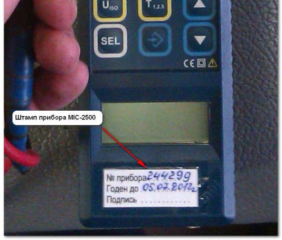
Only serviceable and verified instruments are allowed to work with insulation resistance measurements.
Insulation resistance standards for various cables.
To determine the standard cable insulation resistance, you need to classify them. Cables according to their functional purpose are divided into:
- above 1000 (V) - high-voltage power
- below 1000 (V) - low-voltage power
- control cables - (protection and automation circuits, secondary switchgear circuits, control circuits, power supply circuits for electric drives of switches, separators, short circuiters, etc.)
Insulation resistance measurement for both high-voltage cables and low-voltage cables is carried out with a megohmmeter for a voltage of 2500 (V). And control cables are measured at a voltage of 500-2500 (V).
Each cable has its own insulation resistance standards. According to PTEEP and PUE.
High-voltage power cables above 1000 (V) - the insulation resistance must reach at least 10 (MOhm)
Low voltage power cables below 1000 (V) - insulation resistance should not fall below 0.5 (MΩ)
Control cables - insulation resistance should not fall below 1 (MΩ)
Algorithm for measuring the insulation resistance of high-voltage power cables.
To understand and simplify the process of performing measurement work insulation resistance in high voltage power cables, we recommend the procedure for taking measurements.
1. Check the absence of voltage on the cable using a high voltage indicator
2. We install a test ground using special clamps on the cable conductors on the side where we will carry out the measurement.
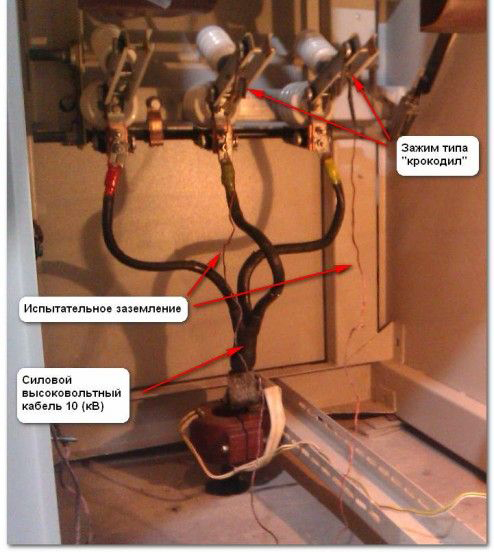
3. On the other side of the cable we leave free conductors, while we separate them at a sufficient distance from each other.
4. We place warning information posters. It is advisable to place a person on the other side to monitor safety while measuring with a megohmmeter.
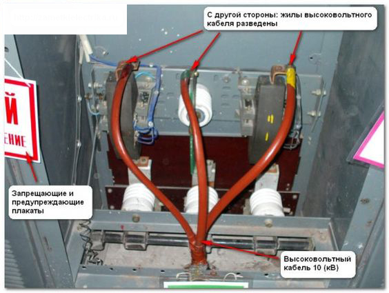
5. We measure each core for 1 minute with a 2500 (V) megohmmeter to obtain the indicators insulation resistance power cable.
For example, we measure the insulation resistance on the conductor of phase “C”. At the same time, we place the grounding on the conductors of phases “B” and “A”. We connect one end of the megohmmeter to grounding, or, more simply, to “ground”. The second end is to the core of phase “C”.
Visually it looks like this:
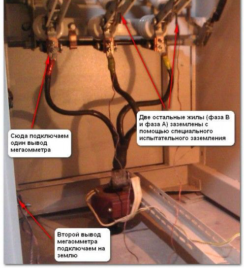
6. We record measurement data in the process of work in a notebook.
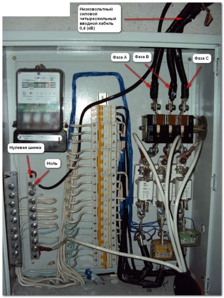
Methodology for measuring insulation resistance of low-voltage power cables.
As for measuring the insulation of low-voltage power cables, the measurement technique differs slightly from that described above.
Likewise:
1. We check that there is no voltage on the cable using protective equipment designed for work in electrical installations.
2. On the other side of the cable, we separate the conductors at a sufficient distance from each other and leave them free.
3. We place prohibition and warning posters. We leave a person on the other side to monitor safety.
4.Measurement insulation resistance of low voltage power cable run a megohmmeter at 2500 (V) for 1 minute:
- between phase conductors (A-B, B-C, A-C)
- between phase conductors and zero (A-N, B-N, C-N)
- between phase conductors and ground (A-PE, B-PE, C-PE), if the cable is five-core
- between zero and ground (N-PE), having previously disconnected zero from the zero bus
6. We record the obtained insulation resistance measurements in a notebook.
Methodology for measuring the insulation resistance of control cables.
![]()
A special feature of measuring the insulation resistance of control cables is that the cable cores can not be disconnected from the circuit and measurements can be taken together with the electrical equipment.
The insulation resistance of the control cable is measured using a familiar algorithm.
1. We check that there is no voltage on the cable using protective equipment that is designed for work in electrical installations.
2. We measure the insulation resistance of the control cable with a megohmmeter of 500-2500 (V) in the following sequence.
First, we connect one terminal of the megohmmeter to the core being tested. We connect the remaining cores of the control cable to each other and to the ground. To the second terminal of the megohmmeter we connect either the ground or any other non-tested conductor.
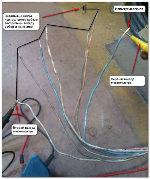
We take 1 minute to measure the core being tested. Then we return this core to the rest of the cable cores and measure each core one by one.
3. We record all the obtained indicators for measuring the insulation resistance of the control cable in a notebook.
Protocol for measuring cable insulation resistance.
All of the above electrical measurements, after obtaining cable insulation resistance data, must be subjected to a comparative analysis with the requirements and standards of PUE and PTEEP. Based on the comparison, it is necessary to formulate a conclusion about the suitability of the cable for subsequent operation and draw up a protocol for measuring insulation resistance.
Each electrical equipment, including conductors, has its own specific parameters. Sometimes, in order to install electrical wiring, you need to clarify each characteristic. It is imperative to know the value of the cable insulation resistance standard, since without this parameter there is no point in carrying out installation work.
The conductor structure is made in this way: two metal cores are designed to transmit current, but they cannot exist independently, since they are afraid of factors acting from the external environment, and are also an unfavorable phenomenon themselves. First of all, metal conductors will interfere with each other until an emergency situation is created. Therefore, insulating materials are required. To avoid accidents, fires or electric shocks, materials that do not conduct current are used in the production of conductive cables.
To make such insulation and, accordingly, protect a person from negative situations, rubber, plastic and other consistencies are taken as a basis. Sometimes they are mixed to create an insulating combination with added strength. Today on the industry market there are all kinds of cables with effective insulation, using which in installation it is important to calculate the resistance.
Insulation resistance: standard table and calculation principle
Table of wire insulation resistance standards
We ask you to pay attention to the tabular data; the standard indicator for each individual voltage class of the electrical network is indicated here.
So, let's start looking at some rules regarding resistance measurements. Unfortunately, it is impossible to directly check the required dielectric value. For the further procedure we will need a megohmmeter.
- The first thing we will do is make sure that the wiring being tested is not connected to voltage;
- then you should ground all current-carrying conductors for just a few minutes. This is done to remove the remaining charge;
- the insulating layer must be dry and clean, therefore, we remove all impurities of dust and dirt, if any.
In the future we will work with the device. To do this, select the measurement aisle. For example, for home electrical networks it is enough to supply 1000 Volts. At the same moment, you need to check the device. This method is performed strictly with closed and open conductors. When open, the needle shows zero, and when closed, it should go to “infinity.”
The PUE standard for cable insulation resistance must confirm the value on the ohmmeter dial.
Important! It is necessary to take readings from the device after measurements only when its needle is at rest.
Remember that resistance cable insulation should be checked at the 15th and 60th seconds from the beginning of rotation of the ohmmeter handle.
It is not uncommon to see insulated wires that are grounded; in such a situation, three measurements are performed:
- between zero and phase;
- between ground and phase;
- between ground and zero.
Important! When working with a megohmmeter, use protective clothing and non-conductive gloves.
To find out what insulation resistance a cable should have, you need to refer to the PUE standards for each individual cross-section.
Control measurements of insulating coating
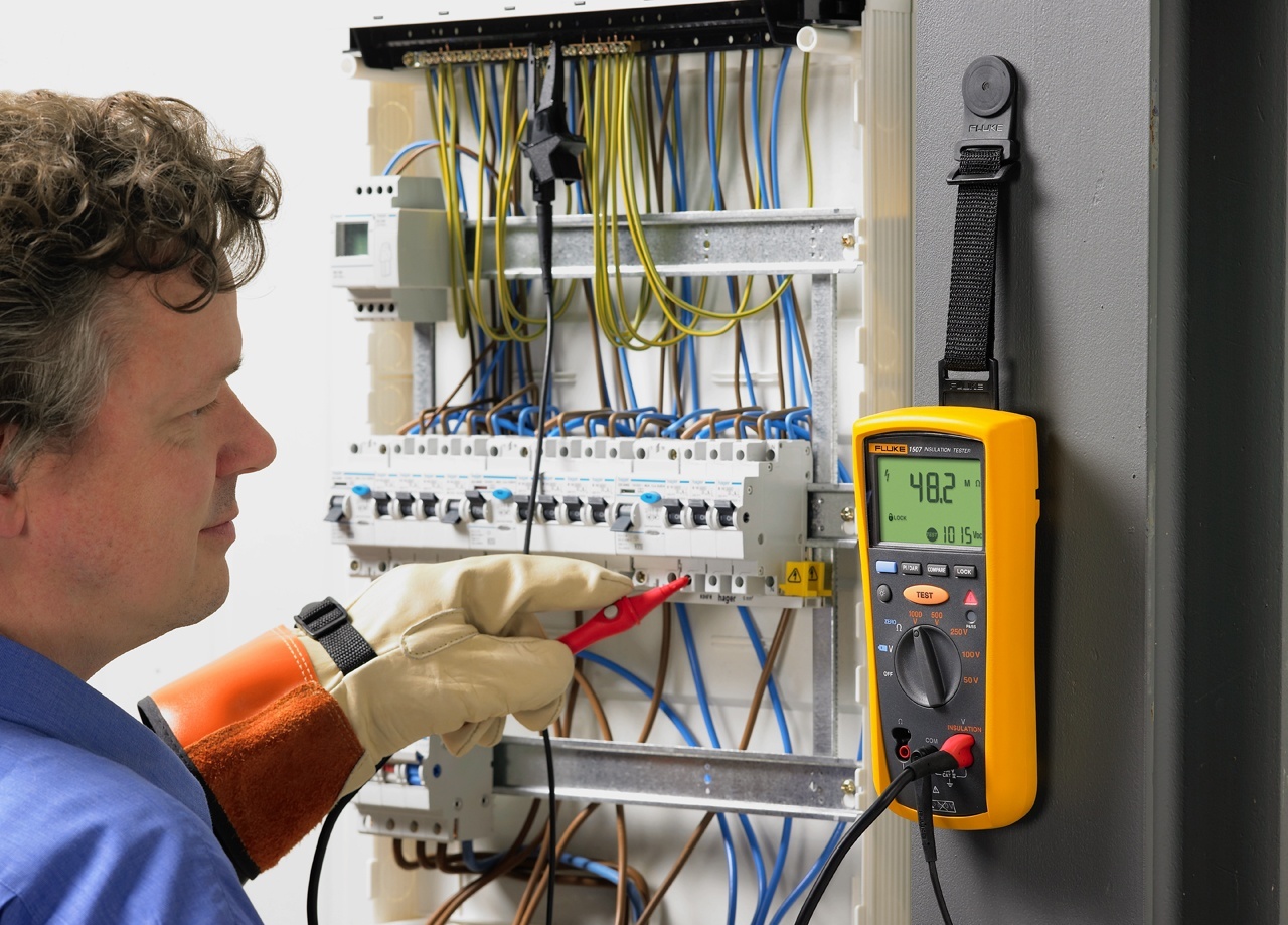
Checking the insulation resistance of wires in the electrical panel
Cable insulation resistance is a very important indicator that indicates the performance of the conductor. To avoid unexpected breakdowns and to avoid the risk of electric shock, it is recommended to carry out regular inspections. We will explain below what it means.
Please note that the check electrical networks and installations with current consumption must be carried out, state regulations and a number of normative documents state this.
Therefore, it is necessary to control:
- resistance of numerous mobile installations strictly every six months;
- resistance of wires and electrical cables in production, as well as external electrical installations no later than every year;
- the resistance of the remaining elements with the consumption of electric current is sufficient once every two and a half years.
Important! It is customary to record all measurement results in a state act, and if a discrepancy is observed, it must be indicated.
In conclusion, we would like to note that only timely monitoring and taking into account all regulations increases the chances of the conductors working longer.
It is carried out with metal conductors in order to determine its performance. The quality of the signal transmitted through the conductors also depends on this indicator. The result of a decrease in insulation resistance, as a rule, is the appearance of interference on the line, which, in turn, leads to audible noise (telephone line), a decrease in throughput (digital data transmission systems), or a complete interruption of the message.
According to GOST 15125-92, measurement of the insulation resistance of a communication cable should be carried out once every 6 months.
Communication cable insulation resistance standards
Electrical standards for communication cables determine minimum values resistance of external insulation and core insulation at which cable products are allowed for use. The amount of resistance depends on the type and purpose of the cable.
Requirements for the insulation resistance values of cables put into operation are given in GOST 15125-92, OST 45.01-98, OST 45.83-96 and other regulatory and technical documentation. Let's look at a few examples.
Insulation resistance standards for communication cables most often used for the construction of primary networks, GTS and other lines (values per 1 km of cable length, without terminals / with terminal devices):
Cables with tubular-paper and porous-paper insulation (, etc.) - 8000/1000 MOhm.
. Polyethylene insulation (brands -, and others) - 6500/1000 MOhm.
. Cord-paper insulation (, etc.) - 10000/3000 MOhm.
Testing of communication cables
Measuring the insulation resistance of a communication cable is also carried out in accordance with regulatory requirements. When performing this task, it is important to take into account the current temperature and humidity. All electrical parameters of communication cables are given by the manufacturers, subject to testing at a temperature of +20 °C and a cable product length of 1 km. Deviation of these parameters from the norm leads to an increase or decrease in readings. However, there are simple formulas that allow you to recalculate the resistance depending on temperature and length.
Equipment
The insulation resistance of a communication cable is measured using a special device called a megohmmeter. To determine the required electrical quantity, these devices generate a certain voltage (from 100 V or more).
Currently, two types of megohmmeters are used - digital and analog. In the first case, electromechanical (manual) generators and dial indicators are used to generate voltage. Digital megohmmeters usually use galvanic cells or batteries to generate voltage. The measurement results are displayed on a digital display. Also, some megohmmeter models do not have their own current generator and require an external power source.
To test cable lines, reflectometers are also widely used, capable of detecting various cable defects using the location (reflectometric) method. The operating principle of the devices is as follows:
Short-wave electrical pulses are applied to the cores of the cable being tested.
. If there are any defects in the cable, the supplied pulse is reflected from the obstacle and returns back to the device.
. The returned signal is captured by the reflectometer sensors, measured, analyzed, and then the measurement result is displayed on the display.
Thus, with the help of reflectometers, it is possible to detect breaks, short circuits, mixed-up pairs, dense ground and other defects that occur, including when the cable insulation is damaged.
Requirements and testing methods for communication cables
Measuring the parameters of communication cables (insulation) is a simple process, but requires compliance with the requirements established by regulatory documentation (in particular, GOST 3345-76, GOST 2990-78). In short:
Before carrying out work, the cable must be de-energized and disconnected from all terminal devices and conductors (if it is, for example, a GTS cable, the tested conductors are disconnected from the terminals of the distribution boards).
. You cannot test with a megohmmeter over cables located in close proximity to other electrical systems, since the voltage generated by the device can create powerful electromagnetic fields that can disrupt the operation of these systems.
. It is impossible to test overhead communication lines during a thunderstorm.
. The tested conductors (cores) must be grounded.
. The test conductor can be disconnected from the ground only after it has been connected to the corresponding terminals of the megohmmeter (i.e., the device is first connected, and only then the wires are disconnected from the ground).
. Before and after measurements, the conductor must be cleared of residual current by short circuiting. This operation is also performed on the measuring probes of the megohmmeter.
. To obtain an accurate result, current is passed through the conductor under test for (and no more than!) 1 minute. After testing, the device and the tested conductor are allowed to “cool down” for 2 or more minutes, unless other numbers are given in the relevant documentation for the megohmmeter and/or cable.
. All other safety requirements are given in GOST 2990-78.
Now let's consider the process of measuring the insulation resistance of a communication cable using the example of a coaxial pair without a protective shield (we will measure the insulation resistance of the cores). According to GOST 2990-78, the conditional diagram for applying voltage to the cable cores is as follows:
Core “1” is connected to the “R-” input (the input can also be designated as “-”, “Ground” or “3”) of the megohmmeter.
. Core “1” and the “R-” input of the megohmmeter are grounded.
. Core “2” is connected to the voltage source input “R+” (“+”, “Rx”, “Line” or “L”) of the megohmmeter.
Conditional working diagram:
![]()
Measurement process:
First, the output voltage level is set on the megohmmeter, which depends on the brand of the cable being tested (usually, to test communication cables, it is enough to apply a voltage of 500 V).
. After applying voltage to the circuit, the megohmmeter will take about 1 minute to take measurements. If it is a pointer device, you must wait until it stops completely; for this, the megohmmeter must be stationary. In the case of digital devices, this is not necessary.
. If necessary, measurements are carried out several times. As mentioned above, before each procedure the device is allowed to “cool down” for about 2 minutes (plus or minus - depends on the characteristics of the megohmmeter).
The readings are greatly influenced by the ambient temperature (the higher it is, the lower the resistance and vice versa). If its value is different from +20 degrees, you must use the following “correction” formula:
R_(20)=K*R_1, where:
R_(20) - cable insulation resistance (in our case, core insulation resistance) at +20 °C (indicated in the data sheet for the cable brand);
R_1 - resistance obtained as a result of measurements at a temperature other than +20 ° C;
K is a “correction” coefficient that allows you to determine the value of insulation resistance that would occur at +20 °C (coefficients are given in the appendix to GOST 3345-76).
For example, let's take a polyethylene-insulated cable whose initial resistance (without termination devices) is 5000 MOhm. After measuring the resistance of the conductors at a temperature of 15 °C, we obtained a result of, say, 11,500 MOhm. According to GOST 3345-76, the correction factor “K” in the case of polyethylene insulation of cores is 0.48. Substituting this value into the formula, we have:
R_(20)=0.48*12500=5520 (resistance under normal conditions)
Using the following formula, you can determine the insulation resistance depending on the cable length:
R=R_(20)* l, where:
R_(20) - insulation resistance at +20 °C;
l is the length of the cable being tested;
Let's take the same brand of cable 1.5 km long. We know the initial insulation resistance of the cores under normal conditions - 5000 MOhm. From here:
R=6500* 1.5=7500 MOhm
The company "Kabel.RF" is one of the leaders in the sale of cable products and has warehouses located in almost all regions Russian Federation. By consulting with the company’s specialists, you can purchase the brand you need at competitive prices.
METHODOLOGY
measuring the insulation resistance of electrical equipment
multifunctional electrical tester (type MET-5035)
1. INTRODUCTION.
DC insulation resistance measurement is the most common type of insulation monitoring. The essence of the method is to measure the ratio of the DC voltage applied to the insulation U current flowing through it i
|
R= |
U |
||
|
i |
Taking into account the equivalent circuit of the dielectric, the total current flowing through the insulation
i=i well +i abs+i o ,
i SLE- through conduction current;
i abs- absorption current due to slow polarization processes;
i o- current. caused by processes of rapid polarization.
Since the current io proceeds only for 10 –12 ... 10 –14 s, then its influence on the measurement results does not affect, whereas the value of the absorption component iabs plays a very significant role, i.e. in the measurement circuit, until the completion of the polarization processes of the dielectric, a current will flow, decreasing in time at a rate depending on the constant τ abs =R abs *C abs
Therefore, the measured resistance value during this period will depend on the duration of the applied voltage.
As the time from the start of the measurement to the time of counting increases, the measured resistance value increases.
To ensure uniformity of measurements, it is customary to take instrument readings every 60 seconds. after applying the measuring voltage to the insulation.
2.NORMS, PERIODICITY AND MEASUREMENT ERROR
2.1. According to the PUE and PTEEP:
2.1.1. Insulation resistance of electrical wiring and cable lines with voltage up to 0.4 kV. inclusive must be at least 0.5 mOhm (Table 1.8.39. PUE, Table 37, Appendix 3.1. PTEEP).
2.1.2. The insulation resistance of switchgears, switchboards and conductors must be at least 1 mOhm (Table 37, Appendix 3.1. PTEEP).
2.1.3. The insulation resistance of stationary electric stoves must be at least
1 mOhm (Table 37 appendix 3.1. PTEEP).
2.1.4. The insulation resistance of cranes and elevators must be at least 0.5 mOhm (Table 37, Appendix 3.1. PTEEP).
2.1.5. The insulation resistance of an electrode boiler without water must be at least 0.5 mOhm, unless higher requirements are specified by the manufacturer. (clause 25.4. appendix 3. PTEEP).
2.1.6. Insulation resistance of stator windings of electric motors alternating current for voltages up to 1000 V there must be at least 1 mOhm at a temperature of 10...30 °C, and at a temperature of 60 °C - 0.5 mOhm (Table 1.8.8. PUE, clause 23.1.2. appendix 3. PTEEP).
2.1.7. The insulation resistance of the rotor windings of electric motors with a wound rotor for voltages up to 1000 V must be at least 0.2 mOhm (Table 1.8.8. PUE, clause 23.1.4. Appendix 3. PTEEP).
2.1.8. The insulation resistance of the windings of DC electrical machines for voltages up to 1000 V depends on the temperature of the winding and the lowest permissible value is determined according to Table 32 of Appendix 3. PTEEP.
2.1.9. If, as a protective measure, insulating rooms are used in which simultaneous touching of parts that are at different potentials is prevented, if the main insulation of current-carrying parts is damaged, the resistance of the insulating floor in such rooms relative to the local ground should be no less than (clause 1.7.86. PUE):
50 kOhm at the nominal voltage of the electrical installation not exceeding 500 V;
100 kOhm at the nominal voltage of the electrical installation above 500 V.
2.2. Insulation resistance is measured for 1 minute with a megohmmeter for voltage:
Power cable lines with voltage up to 1 kV. -2500 V,
Switchgears, switchboards and conductors - 1000…2500 V,
Electrode boilers – 2500 V,
Electrical wiring, cranes and elevators -1000 V.
Electric motors and DC machines up to 500 V – 500 V,
Insulating floors with rated voltage up to and including 500 V - 500 V,
Insulating floors with rated voltages greater than 500 V–1000 V.
2.3. If the insulation resistance of power and lighting electrical wiring is below 1 mOhm, testing is in progress increased voltage industrial frequency 1000 V for 1 min. (clause 28.3.2. app. 3. PTEEP), which can be replaced by testing with a megohmmeter with a voltage of 2500 V (clause 3.6.22. PTEEP).
2.4. Measurement of the insulation resistance of electrical wiring, including lighting networks, is carried out at least once every 3 years, and for electrical wiring in particularly hazardous rooms and outdoor installations of stationary, electric stoves, cranes and elevators - at least once a year (Table 37 appendix 3.1 PTEEP).
Testing of electrode boilers, alternating current electric motors and electrical machines up to 1000 V is carried out within the time limits established by the PPR system.
2.5. The measurement technique provides an error of no more than
+ 0.05% of the scale length when measured with the MET 5035 device
3. MEASUREMENT METHODS
3.1.Measurement of insulation resistance is carried out with a megohmmeter.
The megohmmeter consists of a direct current generator or an alternating current generator with a rectifier, a ratiometer and an additional resistance R1, designed to protect the device in the event of an insulation breakdown. The generator rotates by hand or using a converter
and produces a voltage at the terminals, the value of which corresponds to the rated voltage of the megohmmeter. The current flowing through the device is inversely proportional to the value of the measured resistance Rx, therefore the scale of the device is calibrated directly in megaohms. Megaohmmeters most often use a ratiometer, in which the uneven rotation of the generator has virtually no effect on the readings of the device. This is explained by the fact that the role of the counteracting spring in ratiometers is played by a parallel winding connected to the output voltage of the generator through resistor R2.
When measuring small resistances, the voltage applied to the insulation being measured may be significantly lower than the nominal value.
3.2. To measure the resistance of an insulating floor, a square metal plate with a side of 250 mm is used. A damp cloth is placed between the metal plate and the surface to be measured. The plate is pressed against the surface of the floor or wall with a force of 25 kg. The insulation resistance is measured between the measuring plate and the protective conductor of the electrical installation.
4.SAFETY REQUIREMENTS
4.1. Before starting the tests, it is necessary to make sure that there are no people working on the part of the electrical installation to which the test device is connected and, if necessary, assign an observer.
4.2. The test site, as well as connecting wires that are under test voltage during testing, are fenced.
4.3. A poster is posted on the fences and equipment "Trial. Dangerous for life"
4.4.After completing the test, it is necessary to remove the residual charge from the equipment being tested by briefly (about 1 minute) grounding it.
4.5.Connecting wires must have standard terminations and an insulation resistance of at least 10 mOhm.
4.6. When measuring the insulation of floors and walls in the measurement area, wear dielectric galoshes or boots. The plate is pressed against the wall while wearing dielectric gloves.
5. PERSONNEL QUALIFICATION REQUIREMENTS
5.1. Tests are carried out by a team of at least two people, of whom the work performer must have an electrical safety group of at least IV, and the rest - not lower than III.
5.2. Tests can be carried out by personnel who have undergone special training and have a mark on approval to conduct tests in their industrial safety certificate.
5.3. The team conducting the tests may include persons from the repair personnel with electrical safety group II to perform preparatory work, observation, as well as to disconnect and connect busbars.
6. MEASUREMENT CONDITIONS
6.1.Measurement of insulation resistance should be carried out:
Between current-carrying conductors, taken in turn;
Between each current-carrying conductor and “ground”.
(clause 612.3 GOSTR 50571.16-99)
6.2. Measurements must be made with electrical devices disconnected and fuses removed.
6.3. When measuring insulation resistance in lighting circuits, the lamps must be unscrewed and the switches turned on.
Attention Standards for replacing tests without dismantling the lamp for measuring short-circuit currents from PTEEP are excluded!
6.4. When measuring the insulation of a stand floor, 3 measurements should be made (clause 612.5 of GOSTR 50571.16-99). One of the measurements should be made approximately 1 m from external conductive parts.
6.5. The insulation resistance of floors and walls is measured before applying coatings (varnish, paint, etc.) to the test surfaces.
6.6. For boilers, insulation resistance is measured in the position of the electrodes at maximum and minimum power.
6.7. Electric motor windings that are tightly connected to each other and do not have an outlet for the ends of each phase or branch must be tested against the housing without disconnection (clause 3.6.17. PTEEP).
6.8. In operation, the insulation resistance of the windings of DC electrical machines is measured together with the circuits and cables connected to them (clause 24.2.1. app. 3. PTEEP).
6.9. The insulation resistance of electric stoves is determined when they are heated.

