Star News


Scheme of the simplest voltage regulator for 12 volts. Two simple but reliable current regulator circuits for LEDs in cars
The most important power parameter for any LED is current. When connecting an LED to a car, the required current can be set using a resistor. In this case, the resistor is calculated based on the maximum voltage of the on-board network (14.5V). The negative side of this connection is that the LED does not glow at full brightness when the voltage in the car's on-board network is below the maximum value.
A more correct way is to connect the LED through a current stabilizer (driver). Compared to a current-limiting resistor, the current stabilizer has a higher efficiency and is able to provide the LED with the necessary current both at maximum and at low voltage in the car's on-board network. The most reliable and easy to assemble are stabilizers based on specialized integrated circuits (IM).
Stabilizer on LM317
Three-pin adjustable stabilizer lm317 is ideal for designing simple power supplies that are used in a wide variety of applications. The simplest circuit inclusion of lm317 as a current stabilizer has high reliability and small strapping. A typical lm317 current driver circuit for a car is shown in the figure below and contains only two electronic components: a microcircuit and a resistor. In addition to this circuit, there are many other, more complex circuit solutions for building drivers using many electronic components. Detailed description, principle of operation, calculations and selection of elements of the two most popular circuits on the lm317 can be found.
The main advantages of linear stabilizers built on the basis of lm317 are ease of assembly and low cost of components used in piping. The retail price of the IC itself is no more than $ 1, and the finished driver circuit does not need to be adjusted. It is enough to measure the output current with a multimeter to make sure it matches the calculated data.
The disadvantages of IM lm317 include a strong heating of the case with an output power of more than 1 W and, as a result, the need for heat removal. To do this, a hole for a bolted connection with a radiator is provided in the TO-220 case. Also, the maximum output current, not more than 1.5 A, can be considered a disadvantage of the above circuit, which sets a limit on the number of LEDs in the load. However, this can be avoided by parallel connection several current stabilizers or use an lm338 or lm350 chip instead of lm317, which are designed for more high currents loads.
Stabilizer on PT4115
PT4115 is a unified chip developed by PowTech specifically for building drivers for powerful LEDs which can also be used in the car. A typical PT4115 switching circuit and the formula for calculating the output current are shown in the figure below. 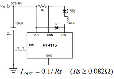
It is worth emphasizing the importance of having a capacitor at the input, without which the PT4115 IM will fail the first time it is turned on.
You can understand why this happens, as well as get acquainted with a more detailed calculation and selection of the remaining elements of the circuit. The microcircuit gained fame due to its versatility and a minimal set of parts in the strapping. To light an LED with a power of 1 to 10 W, a motorist just needs to calculate the resistor and select the inductance from the standard list.
The PT4115 has a DIM input that greatly expands its capabilities. In the simplest version, when you just need to light the LED at a given brightness, it is not used. But if it is necessary to adjust the brightness of the LED, then either the signal from the output of the frequency converter or the voltage from the output of the potentiometer is fed to the DIM input. There are options for setting a specific potential at the DIM pin using a MOSFET. In this case, when power is applied, the LED lights up to full brightness, and when the MOSFET starts, the LED dims by half.
The disadvantages of the LED driver for cars based on PT4115 include the difficulty of selecting a current-setting resistor Rs due to its very low resistance. The life of the LED directly depends on the accuracy of its value.
Both considered microcircuits have proven themselves in the design of drivers for LEDs in a car with their own hands. The LM317 is a well-known, proven linear regulator, the reliability of which is beyond doubt. A driver based on it is suitable for organizing interior lighting and dashboard, turns and other elements of LED tuning in cars.
The PT4115 is a newer integrated regulator with a high power MOSFET output, high efficiency and dimmability.
Read also
LED crafts, as well as various kinds of lighting, are becoming more common today. However, as soon as one LED stops working, the whole impression of light disappears. To do this, so that disappointment does not overtake, it is worth using stabilizers that are installed on LED structures.
The simplest do-it-yourself stabilizer
If you understand the reason why the burnout occurs LED lamps, then everything is simple here. It's no secret that all the LED elements that decorate the car in such an original way are designed to operate at a constant voltage of 12 volts. But the voltage that the on-board network produces practically cannot provide such an indicator. As a rule, it is 15 volts. As a result, the LEDs begin to dim, blink, or stop working altogether.
In order to deal with such a problem, use a voltage stabilizer, which you can create yourself, because this does not require special knowledge.

A 12 volt stabilizer can be purchased at almost any store that sells radio components. You can choose completely different labels. The simplest option is KREN 8B, and it is also worth buying a 1N4007 diode. The latter should be used in order to eliminate the possibility of polarity reversal. At creating a stabilizer diode must be soldered to the input. When the diode is in place, you can start connecting the stabilizers.
After work, you can take measurements. By measuring the voltage that the on-board network gives when the ignition is off, we see that it is 12.24 volts. LED elements may not react to it. But if you turn on the ignition, then the voltage is 14.44. After the stabilizers are installed, it is clear that they are fully doing their job and the voltage is given out no more than 12 volts.
Today it is easy to see that LED elements are being introduced deeper into our lives. There are more and more devices with LEDs, but it happens that one or more bulbs burn out and the beauty of the device fades into the background. This is especially true of handicraft homemade products, where manual labor often prevails. In order to prevent this from happening, it is necessary to put stabilizers on assemblies with LED elements.
It is well known that light bulbs (LED) are designed for a maximum of 12 volts, and it is also known that the on-board voltage in a car can exceed 15 volts, which is detrimental to the above lamps. Due to such sudden voltage surges, LEDs can fail - blink, lose brightness, and so on.
To prevent this from happening, you only need to insert a stabilizer into the assembly. Making a stabilizer, which will be discussed later, does not require special skills and abilities. A 12 volt stabilizer can be easily found at any radio parts store.
The marking of stabilizers can be different, in this case KREN-8B and a 1N4007 diode were used, which is necessary to prevent possible polarity reversal. The diode must be soldered to the input of the stabilizer.
Since I already had a backlight for my legs, respectively, the stabilizer was first connected to this circuit. The voltage with the ignition off is 12.24 volts - this is the battery voltage - this voltage does not pose a threat to the bulbs, and when the engine is running, the voltage jumps sharply to 14.44 volts, which is detrimental to the LEDs.


When you connect the stabilizer, you can easily notice this element clearly copes with its task.

We connect to the illumination of the bottom of the doors. You have to remove the door trim.