Star news


DIY 12 volt voltage stabilizer. Two simple but reliable current stabilizer circuits for LEDs in cars
Today it is easy to notice that LED elements are being introduced deeper and deeper into our lives. There are more and more devices with LEDs, but it happens that one or more light bulbs burn out and the beauty of the device fades into the background. This is especially true for handicrafts, where manual labor often predominates. To prevent this from happening, it is necessary to install stabilizers on assemblies with LED elements.
It is well known that light bulbs (LED) are designed for a maximum of 12 volts, and it is also known that the on-board voltage in a car can exceed 15 volts, which is detrimental to the above-mentioned lamps. Due to such sudden voltage surges, LEDs can fail - blink, lose brightness, and so on.
To prevent this from happening, you just need to insert a stabilizer into the assembly. Making a stabilizer, which will be discussed below, does not require any special skills or abilities. A 12 volt stabilizer can be easily found in any radio parts store.
The marking of stabilizers can be different, in this case we used KREN-8B and a 1N4007 diode, which is necessary to prevent possible polarity reversal. The diode must be soldered to the input of the stabilizer.
Since I already had a backlight for the legs, the stabilizer was first connected to this circuit. The voltage when the ignition is turned off is 12.24 volts - this is the battery voltage - this voltage does not pose a threat to the light bulbs, and already with the engine running the voltage jumps sharply to 14.44 volts, which is detrimental to the LEDs.


When connecting the stabilizer, you can easily notice that this element clearly copes with its task.

We connect to the lighting of the bottom of the doors. You have to remove the door trim.

I think everyone who installed LEDs in a car sooner or later encountered the diodes burning out. This happens due to the fact that in the electrical wiring of a working car the voltage “walks” in the range from 11 to 15 volts, plus various voltage surges, interference and impulses reverse current.
In order to avoid this, it is necessary to install a current stabilizer.
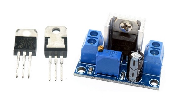
As practice shows, it is best to use the LM317T chip.
Please note that Uout is located not only on the middle leg, but also on the heat sink.
The simplest connection diagram for this microcircuit looks like this:
Please note that our diodes should not consume more than 1.5A in total, otherwise the stabilizer will burn out.
The optimal scheme, of course, is more complicated and looks like this:

The task was this: to assemble a stabilizer so that the input would be 14.5V and the output 12V.
We will need:
1. LM317T chip - 2 pcs.
2. Diode 1N4007 - 2 pcs.
3. Capacitor 1uF 16V - 2 pcs.
4. Capacitor 2.2 microfarads 16V - 2 pcs.
5. Mounting board - 2 pcs.
6. Heat shrink tube according to the size of the board.
7. Soldering iron (or better yet, a soldering station).
8. Straight arms.
All this can be bought, for example, at Chip and Deep or Quartz1 (in Moscow).
The scheme in my case turned out like this:
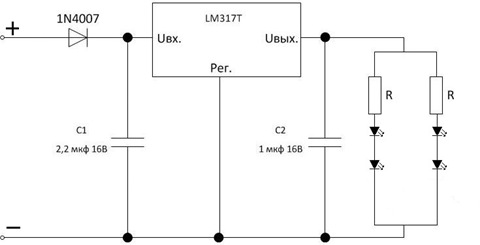
The 1N4007 diode is needed to protect against reverse current pulses, and capacitors are needed to stabilize the voltage when it temporarily drops in the car network (for example, when the turn signals blink).
The circuit on the right with the LEDs is my “angel eyes” - they are non-separable, so the resistors there are factory ones.
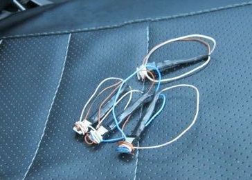
It all turned out like this:

The board is covered with heat-shrink film for sealing and filled with glue-sealant around the edges (well, electronics don’t like water). On the left is a connector for connecting to diodes (the stabilizer will be located outside the headlight).
In general, oddly enough, the thing still works and, I hope, the diode rings will live happily ever after =)
And I also want to note one point: there are modern trucks like JAC, which are very practical and convenient, both in maintenance and operation. In repair ratio, jac spare parts very easy to order and purchase. By purchasing this car you are making the right choice.
LED crafts, as well as various types of lighting, are becoming more common today. However, as soon as one LED stops working, the entire impression of the light disappears. To avoid disappointment, you should use stabilizers that are installed on LED structures.
The simplest do-it-yourself stabilizer
If you understand the reason why LED lamps burn out, then everything is simple. It's no secret that all the LED elements that decorate a car in such an original way are designed to work with constant voltage with an indicator of 12 volts. But the voltage supplied by the on-board network practically cannot provide such an indicator. As a rule, it is 15 volts. As a result, the LEDs begin to dim, blink, or stop working altogether.
In order to combat this problem, it is worth use a voltage stabilizer, which you can create yourself, because this does not require special knowledge.

A stabilizer rated for 12 volts can be purchased at almost any store that sells radio components. You can choose completely different labels. The simplest option is KREN 8B, and it is also worth purchasing a 1N4007 diode. The latter should be used to eliminate the possibility of polarity reversal. At creating a stabilizer diode must be soldered to the input. When the diode is in place, you can begin connecting the stabilizers.
After the work is completed, measurements can be taken. Measuring the voltage provided by the on-board network when the ignition is not working, we see that it is 12.24 volts. LED elements may not react to it. But if you turn on the ignition, the voltage is 14.44. After the stabilizers are installed, it is clear that they fully perform their work and the voltage is output no more than 12 volts.
The most important power parameter for any LED is current. When connecting an LED to a car, the required current can be set using a resistor. In this case, the resistor is calculated based on the maximum voltage of the on-board network (14.5V). The negative side of this connection is that the LED does not glow at full brightness when the voltage in the vehicle's on-board network is below the maximum value.
A more correct way is to connect the LED through a current stabilizer (driver). Compared to a current-limiting resistor, a current stabilizer has a higher efficiency and is able to provide the LED with the required current both at maximum and at undervoltage in the vehicle's on-board network. The most reliable and easiest to assemble are stabilizers based on specialized integrated circuits (ICs).
Stabilizer on LM317
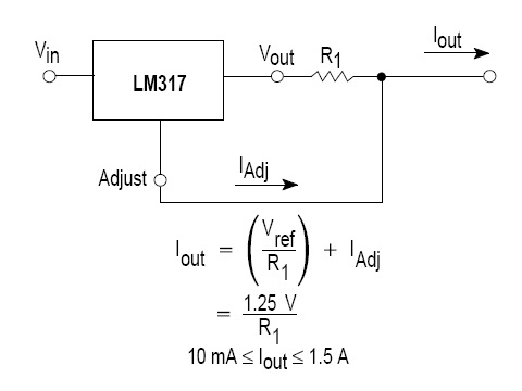
Three-pin adjustable stabilizer lm317 is ideal for designing simple power supplies that are used in a wide variety of devices. The simplest circuit for connecting lm317 as a current stabilizer has high reliability and small wiring. A typical lm317 current driver circuit for a car is shown in the figure below and contains only two electronic components: a microcircuit and a resistor. In addition to this circuit, there are many other, more complex circuit solutions for building drivers using a variety of electronic components. Detailed description, the principle of operation, calculations and selection of elements of the two most popular circuits on lm317 can be found.
The main advantages of linear stabilizers built on the basis of lm317 are ease of assembly and low cost of components used in wiring. The retail price of the IC itself is no more than $1, and the finished driver circuit does not require adjustment. It is enough to measure the output current with a multimeter to ensure that it corresponds to the calculated data.
The disadvantages of the lm317 MM include strong heating of the case with an output power of more than 1 W and, as a consequence, the need for heat removal. For this purpose, the TO-220 type housing has a hole for a bolted connection to the radiator. Also, a disadvantage of the above circuit can be considered the maximum output current, no more than 1.5 A, which sets a limit on the number of LEDs in the load. However, this can be avoided by parallel connection several current stabilizers or use the lm338 or lm350 microcircuit instead of lm317, which are designed for higher load currents.
Stabilizer on PT4115
PT4115 is a unified chip developed by PowTech specifically for building drivers for powerful LEDs, which can also be used in a car. A typical PT4115 connection circuit and the formula for calculating the output current are shown in the figure below. 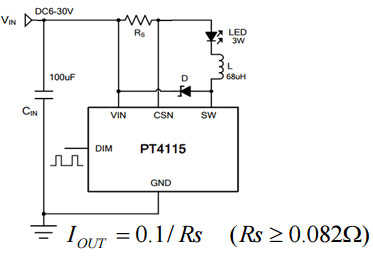
It is worth emphasizing the importance of having a capacitor at the input, without which the PT4115 MI will fail the first time it is turned on.
You can understand why this happens, as well as get acquainted with a more detailed calculation and selection of the remaining elements of the circuit. The microcircuit gained fame due to its versatility and a minimal set of parts in the harness. To light an LED with a power from 1 to 10 W, the car enthusiast only needs to calculate the resistor and select the inductance from the standard list.
The PT4115 has a DIM input that greatly expands its capabilities. In the simplest version, when you just need to light the LED at a given brightness, it is not used. But if it is necessary to adjust the brightness of the LED, then either the signal from the output of the frequency converter or the voltage from the output of the potentiometer is supplied to the DIM input. There are options for setting a specific potential at the DIM pin using a MOSFET. In this case, when power is applied, the LED glows at full brightness, and when the MOSFET starts up, the LED dims the brightness by half.
The disadvantages of an LED driver for cars based on PT4115 include the difficulty of selecting the current-setting resistor Rs due to its very low resistance. The service life of the LED directly depends on the accuracy of its rating.
Both microcircuits discussed have proven themselves to be excellent in constructing drivers for LEDs in a car with their own hands. LM317 is a long-known, proven linear stabilizer, the reliability of which is beyond doubt. A driver based on it is suitable for organizing interior lighting and dashboard, turns and other elements of LED tuning in a car.
PT4115 is a newer integrated stabilizer with a powerful MOSFET transistor at the output, high efficiency and dimming capability.
Read also
Nowadays it is difficult to imagine tuning a car without LED lamps. But sometimes their installation is complicated by the fact that they burn out. To avoid this situation, you can connect a current stabilizer for LEDs to the network with your own hands. The article provides examples of microcircuits that can be used to make it.
Circuits of stabilizers and current regulators
Everyone knows that LED light bulbs Twelve volt power is required. In a car network, this value can reach up to 15 V. LED elements are very sensitive, such surges are reflected negatively on them. LED bulbs may burn out or produce poor-quality light (blink, lose brightness, etc.).
To make the LEDs last longer, drivers (resistors) are included in the car's electrical network. When there is instability in the network, devices are installed that maintain a constant value. There are several simple microcircuits that you can use to make a voltage stabilizer with your own hands. All components included in the chain can be purchased at specialized stores. Having basic knowledge of electrical engineering, making devices will not be difficult.
On Krenka
In order to design the simplest stabilizer voltage 12 volts with your own hands, you will need a microcircuit with a consumption of 12 V. In this case, an adjustable voltage stabilizer 12 V LM317 is suitable. It can operate in an electrical network where the input parameter is up to 40 V. In order for the device to operate stably, it is necessary to provide cooling.
The current regulator on the LM317 requires a small current of up to 8 mA to operate, and this value usually remains unchanged even when high current flowing through the LM317 roll, or when the input value changes. This is implemented using the R3 component.
You can use the R2 element, but the limits will be small. If the resistance of LM317 remains constant, the current flowing through the device will also be stable (author of the video - Created in Garage).
The input value for the LM317 bank can be up to 8 mA and higher. Using this microcircuit, you can come up with a current stabilizer for DRLs. This device can act as a load in the on-board network or a source of electricity when recharging. Making a simple voltage regulator LM317 is not difficult.
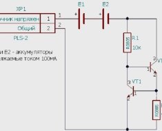
Today, stabilizing devices for the on-board network of a 12 V car, developed using two transistors, are popular. This microcircuit is used as a voltage stabilizer for DRLs.
Resistor R2 is a current-distributing element. As the current in the network increases, the voltage increases. If it reaches a value from 0.5 to 0.6 V, element VT1 opens. Opening component VT1 closes element VT2. As a result, the current passing through VT2 begins to decrease. You can use a Mosfet field-effect transistor together with VT2.
Element VD1 is included in the circuit when the values are in the range from 8 to 15 V and are so large that the transistor may fail. With a powerful transistor, readings in the on-board network of about 20 V are acceptable. Do not forget that the Mosfet transistor will open if the readings at the gate are 2 V.
If you use a universal rectifier as a charger for a battery or other tasks, then it is enough to use resistor R1 and a transistor.
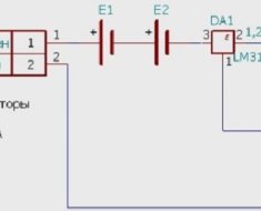
On an operational amplifier (op-amp)
A voltage stabilizer for LEDs based on an op-amp is assembled if it is necessary to create a device that will operate in an extended range. In the case under consideration, the element that will set the rectified current is R7. By using operational amplifier DA2.2, you can increase the voltage level in the current-setting component. The task of the DA 2.1 component is to control the reference voltage.
When creating the circuit, you should take into account that it is designed for 3A, so more current is required, which must be supplied to the XP2 connector. In addition, the functionality of all components of this device should be ensured.
The made stabilizing device for a car must have a generator, the role of which is performed by REF198. To properly configure the device, the slider of resistor R1 must be set to the upper position, and resistor R3 must be used to set the required value of the rectified current 3A. To suppress possible excitations, elements R,2 R4 and C2 are used.
On a pulse stabilizer chip
If a rectifier for a car must provide high efficiency in the network, it is advisable to use switching components, creating a switching voltage stabilizer. The MAX771 circuit is popular.
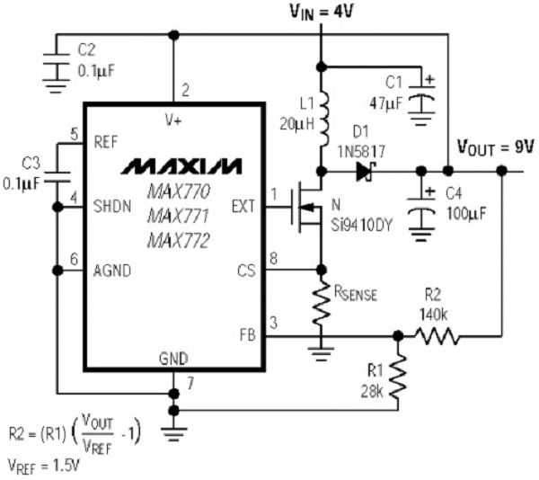
The switching current stabilizer is characterized by an output power of 15 W. Elements R1 and R2 divide the output of the circuit. If the divided voltage exceeds the reference voltage, the rectifier automatically reduces the output value. Otherwise, the device will increase the output parameter.
Assembly of this device is advisable if the level exceeds 16 V. R3 components are current. To eliminate the high load drop across this resistor, an op-amp should be included in the circuit.
Conclusion
We examined voltage stabilizers on various components. These schemes can be made more complex, increasing performance and improving other indicators. You can use ready-made microcircuits, which you can always improve with your own hands, creating devices designed to perform specific tasks.
Photo gallery “Microcircuits for homemade rectifiers”

Developing microcircuits for LEDs in cars is a labor-intensive and complex undertaking that requires special knowledge and experience. In their absence, it will be difficult to achieve the desired result.
But experience can be gained by carefully assembling a simple current stabilizer for LEDs according to the diagrams given. It can be used for daytime running lights in your car with LED bulbs installed.
Video “Do-it-yourself LED rectifier”
Video about how to make a device that will protect LEDs from burning out (the author of the video is Yakov TANK_OFF).

