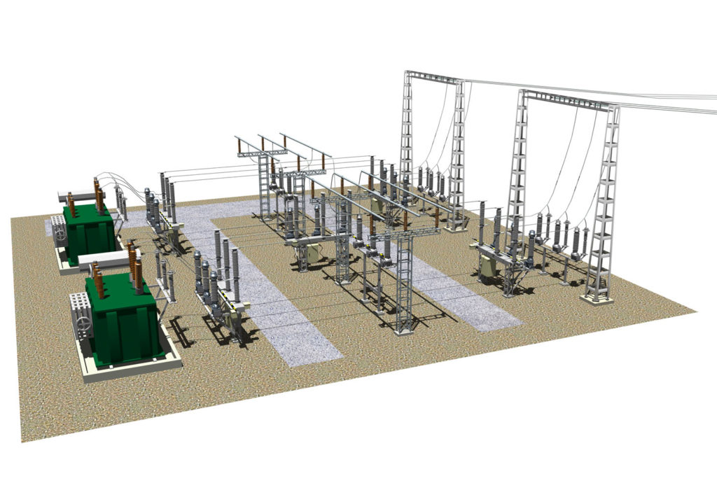
Typical design of a brick transformer substation. Design standards for transformer substations
The design of complete transformer substations (CTS) is a set of calculations, i.e. preliminary design of the facility and connection diagrams, which are necessary for the preparation and argumentation of the solutions and proposals presented in the technical specifications (TOR). It can be noted that in the event of the absence and impossibility of developing technical specifications for the customer on its own, the performing organization independently prepares this document, after agreeing on all issues with the client (customer) of the technical specifications project.
Designing a package transformer substation is a very complex process that requires special skills. It should be remembered that saving on this work can lead to negative consequences, such as, for example, ultimately obtaining not very high-quality circuits, which will certainly lead to additional difficulties during further operation of the package transformer substation.
This service is very common nowadays. It is ordered by many clients, for industrial facilities, to provide electricity to private and apartment buildings, etc.
The design of a PTS represents (as stated above) the carrying out of calculations, which are indicated in the technical specifications. It includes many necessary documents and definitions with calculations of equipment operating modes, technical solutions and their justifications, necessary connection and installation diagrams power cables. Type, type of substation, location (installation), proposals for electricity metering, TP efficiency indicators. Also included in this package of documents are calculations for the mode of connecting substations to the central electrical network and a drawing with the connection of all the necessary safety devices, such as switches, protection devices and others.

After the design has been completed in accordance with all regulatory requirements, complete transformer stations are manufactured and delivered to the construction site already assembled or in the form of modules, therefore the definitions indicated above are necessary when developing a package transformer substation project. In turn, TP manufacturers determine:
- purpose and conditions under which the substation will be operated
- Possible options for additional equipment and TP composition
- device and operating principle of TP
- features and installation option
- necessary procedures for preparing the TP for operation and connecting it to the network
- maintenance, operating rules, safety measures
Design Features
Transformer substations are divided into several main types. It is customary to divide substations into built-in and freestanding (based on installation features).
The design itself can be divided into three types:
- 35 kV TP project. Provides for an open or closed structure. The type itself will depend on the location and operating conditions of the transformer substation, as well as on the technical specifications. The number of power transformers is determined by the electrical circuit of the substation.
- 10 kV transformer substation project. Designed for medium and low voltage substations up to 10 kV. The main necessary information for design is data on one-time load, voltage regulation, insulation, overvoltage protection and other information in accordance with the operating conditions of the transformer substation and its regulatory requirements.
- 110 kV transformer substation project. This project is designed for the introduction of relatively large objects into the electrical system, such as residential areas, small towns, or for power supply to manufacturing enterprises or industrial zones. The calculations take into account the degree of workload, operating voltage levels, etc., and the design is often supplemented by a feasibility study procedure.
Price
The cost of designing a transformer substation is calculated individually and will depend on many important factors: the type of substation, the features of its construction, any additional services, but most importantly, the complexity and total volume of work performed.
Before the beginning transformer substation design it is necessary to obtain technical conditions for connecting power to the networks of the electric grid company. The technical specifications prescribe the type of transformer substation, voltage level, connection point and power of the transformer substation. Before starting the design of the TP, it is recommended to draw up a detailed technical task to design a TP with the customer, since the technical specifications describe only the basic requirements for the TP, but do not describe the location and execution of the TP. The placement of transformer substations takes place according to the geobasis (territory plan with the drawing of utilities and buildings on a scale of 1:2000) of the consumer’s territory. The basic rule when planting a transformer substation is to locate the substation in the center of the loads. The consumer must have registered land rights for the transformer substation or registered land allotment for the construction of a transformer substation. The final alignment is carried out according to the territory improvement project with vertical marks. The improvement project marks the access routes to the transformer substations, and this is important due to the complexity of installing heavy transformers and subsequent maintenance of transformer substations. On the vertical layout, the vertical landing mark of the transformer substation is set. Without vertical planning of the territory, it may later turn out that the TP is located in the ground up to the roof, since backfilling of the top layer of soil occurs only after all construction work is completed. There are various types of transformer substations: block-type complete transformer substations BKTP, complete transformer substations KTP, complete transformer substations of external design KTPN, kiosk-type transformer substations, mast-type transformer substations, cabinet-type transformer substations, etc. They differ in the type of cable entry, number of transformers, and design. Schemes of transformer substations are typical and adapt to a specific situation. Subject to change electrical diagram transformer substation in terms of the number of low-voltage cells and protection devices on the low side (fuses or circuit breakers). Transformers are selected from the range 16 25 40 63 100 160 250 400 630 1000 1600 2500 kVA. The transformer substation building or its construction design can be selected. It is not recommended to make changes to the standard design of the TP, but in the case of an individual TP, you can choose based on your preferences and financial costs. Typically, the transformer substation building is made of concrete panels, sandwich panels, monolith or sheet iron. Design standards for transformer substations require careful grounding of the transformer transformer, since the grounding conductor comes from the transformer transformer to the low-voltage input device and can be used for grounding the electrical installation.
© All materials are protected by the Russian Federation copyright law and the Civil Code of the Russian Federation. Full copying is prohibited without permission from the resource administration. Partial copying is permitted with a direct link to the source. Author of the article: team of engineers from OJSC Energetik LTD


