Star news


Calculation of the quenching capacitor in the transformer power supply. Transformerless power supplies, voltage converters without a transformer. Calculation. Calculate online, online
Sometimes in electrical engineering power supplies that do not contain a transformer are used. In this case, the task of reducing the input voltage arises. For example, a decrease AC voltage mains (220 V) at a frequency of 50 hertz to the required voltage value. An alternative to a transformer is a capacitor, which is connected in series with the voltage source and load (for more information on the use of capacitors, see section "). Such a capacitor is called a quenching capacitor.
To calculate a quenching capacitor means to find the capacitance of a capacitor that, when connected to the circuit as described above, will reduce the input voltage to the required voltage at the load. Now we get the formula for calculating the capacity of the quenching capacitor. Capacitor operating in a circuit alternating current, has a capacitance (), which is related to the frequency of the alternating current and its own capacitance () (and), more precisely:
![]()
According to the condition, we included a resistance (resistive load()) and a capacitor in the alternating current circuit. The total resistance of this system () can be calculated as:
Since the connection is serial, using , we write:
![]()
where is the voltage drop across the load (device supply voltage); - mains voltage, - voltage drop across the capacitor. Using the above formulas, we have:
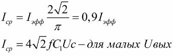
If the load is small, then using a capacitor, including it in series in the circuit, is the easiest way to reduce the mains voltage. If the voltage at the power output is less than 10-20 volts, then the capacity of the quenching capacitor is calculated using the approximate formula:
![]()
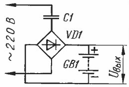
In such a power source, a series-connected capacitor and load are connected to an alternating voltage network. Let us first consider the operation of a source with a purely resistive load (Fig. 1, a).
From the course of electrical engineering it is known that the total resistance of the capacitor C1 and resistor Rn connected in series is equal to:
where X c 1 =1/2n*f*C1 is the capacitance of the capacitor at frequency f. This is
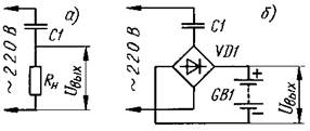
Fig.1
mu effective alternating current in the circuit Ieff = Uс/Z (Uc is the supply voltage). The load current is related to the capacitance of the capacitor, the output voltage of the source and the mains voltage as follows:
For low output voltages
Ieff=2l*f*C1*Uс.
As an example useful in practice, we will calculate a quenching capacitor for connecting a 127 V soldering iron with a power of 40 W to a 220 V network. Required effective value of load current Ieff=40/127=0.315 A. Design capacitance of the quenching capacitor
For the operation of heating devices, it is the effective current that is important. However, if the load is, for example, a rechargeable battery connected to the diagonal of the rectifier bridge (Fig. 1, b), it will be charged by an average non-rectified (pulsating) current, the numerical value of which is less than Ieff:
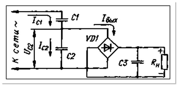
In amateur radio practice, a source is often used in which a quenching capacitor is connected to the network in series with a diode bridge, and the load, shunted by another capacitor, is powered from the output diagonal of the bridge (Fig. 2). In this case, the circuit becomes sharply nonlinear and the shape of the current flowing through the bridge and the quenching capacitor will differ from sinusoidal. Because of this, the calculation presented above is incorrect.
What are the processes occurring in a source with a smoothing capacitor C2 with a capacitance sufficient to consider the output voltage ripple to be negligible? For the damping capacitor C1, the diode bridge (together with C2 and Rн) in steady state is a kind of equivalent of a symmetrical zener diode. When the voltage at this equivalent is less than a certain value (it is almost equal to the voltage Uout on capacitor C2), the bridge is closed and does not conduct current; when it is higher, current flows through the open bridge, preventing the voltage at the bridge input from increasing.
We will begin our consideration from moment ti, when the network voltage is maximum (Fig. 3). Capacitor C1 is charged to the amplitude voltage of the network Us.amp minus the voltage on the diode bridge uм, approximately equal to Uout. The current through capacitor C1 and the closed bridge is zero. The voltage in the network decreases according to a cosine law (graph 1), on the bridge it also decreases (graph 2), and the voltage on capacitor C1 does not change.

The capacitor current will remain zero until the voltage on the diode bridge, changing sign to the opposite, reaches the value -Uout (moment t2). At this moment, current lei appears abruptly through capacitor C1 and the bridge. Starting from moment t2, the voltage on the bridge does not change, and the current is determined by the rate of change of the network voltage and, therefore, will be exactly the same as if only capacitor C1 was connected to the network (graph 3).
When the network voltage reaches a negative amplitude value (moment t 3), the current through capacitor C1 will again become zero. The process is then repeated every half-cycle.
The current through the bridge flows only in the time interval from t 2 to t 3, its average value can be calculated as the area of the shaded part of the sinusoid in graph 3. Simple calculations, which, however, require knowledge of differential and integral calculus, give the following formula for the average current Iav through load Rн:
![]() (2)
(2)
At low values of the output voltage, this formula and the previously obtained (1) give the same result. If in (2) the output current is equated to zero, we obtain Uvyx=Uc*2 ^1/2, i.e., with a load current equal to zero (in case of accidental disconnection of the load, say, due to an unreliable contact), the output voltage of the source becomes equal to the amplitude voltage of the network. This means that all elements of the source must withstand such voltage. When the load current decreases, for example, by 10%, the output voltage will increase so that the expression in parentheses also decreases by 10%, i.e. by approximately 30 V (at Uout = 10 V). Conclusion - turning on the zener diode in parallel with the load Rн (as shown by dashed lines in Fig. 2) is almost mandatory.
For a half-wave rectifier (Fig. 4), the current is calculated using the following formula:
![]()
Naturally, at low values of the output voltage, the load current will be half as much as for a full-wave rectifier, and the output voltage at zero load current will be twice as high - after all, this is a rectifier with doubling the voltage!
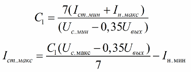
The procedure for calculating sources according to the diagram in Fig. 2 next. First, the output voltage Uout, the maximum In max and minimum I n min values of the load current, the maximum Uc max and minimum Uc min values of the network voltage are set. It was already indicated above that when the load current changes, a zener diode connected in parallel with the load Rн is required. How to choose it? At a minimum network voltage and a maximum load current, a current of at least the permissible minimum stabilization current of 1st min must flow through the zener diode. You can set the value within 3...5 mA. Now determine the capacitance of the quenching capacitor C1 for the full-wave rectifier:
C1 =3.5(Ist min+ln max)/(Uc min-0.7Uvyx). (3)
The formula is obtained from (2) by substituting the corresponding values. The current in it is in milliamps, the voltage is in volts; The capacitance will be in microfarads. The calculation result is rounded to the nearest higher denomination; you can use a battery of several capacitors connected in parallel.
I st max =(U c max -0.7Uout)С 1 /3.5-I n min (4)
In the absence of a zener diode for the required voltage Uout, which allows the calculated maximum stabilization current, you can connect several zener diodes at a lower voltage in series or use an analogue of a powerful zener diode.
The minimum load current In mm should be substituted into formula (4) only when this current is long-lasting - a few seconds or more. With a short-term minimum load current (fractions of a second), it must be replaced with an average (over time) load current. If the zener diode allows a current greater than that calculated by formula (4), it is advisable to use a quenching capacitor of a slightly larger capacity to reduce the requirements for the accuracy of its selection.
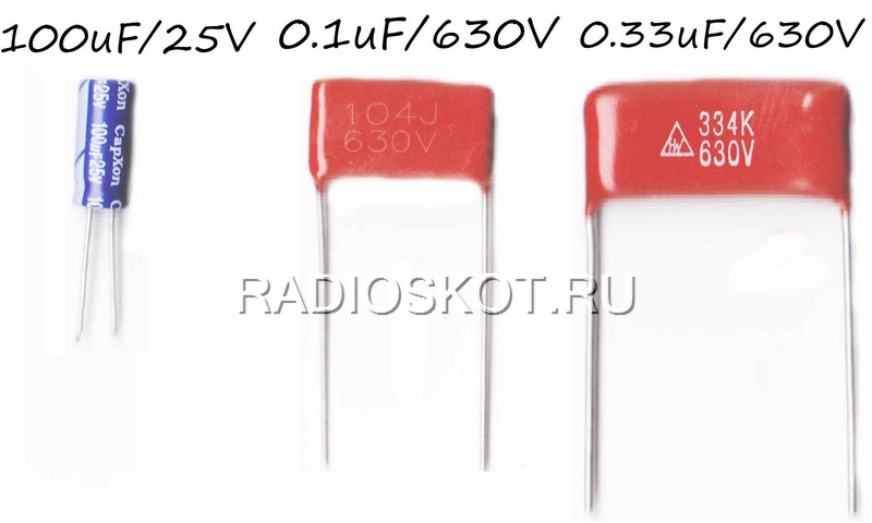
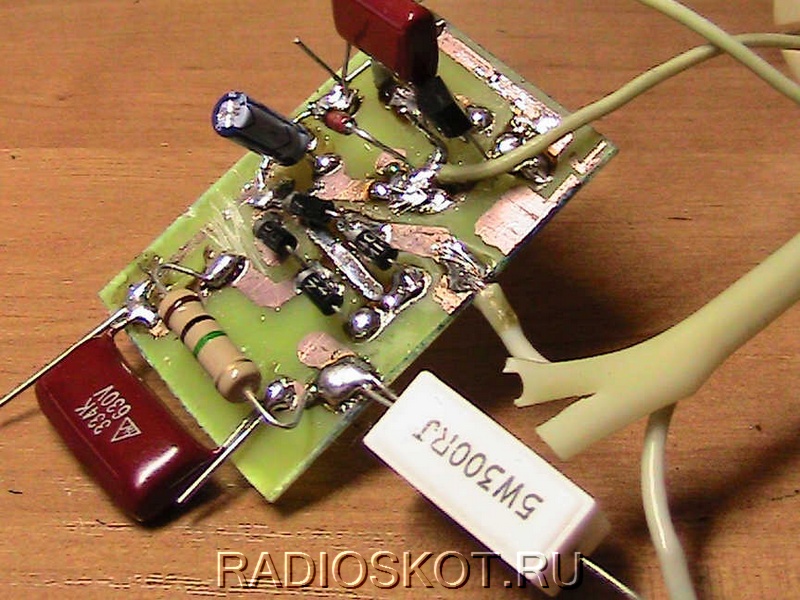
I needed a power supply for a homemade mini-drill made from a 17-volt motor. I reviewed many circuits of various power supplies, but they all used a transformer, which I don’t have, and I’m somehow reluctant to buy. Then I decided to do something simpler and collect power for this voltage - 17 Volts. The circuit is quite simple, such a ready-made power supply needs to be supplied with 220 volts of alternating voltage, in short, power the circuit from an outlet, and at the output we get 17 volts of direct voltage. Typically, power sources of this type are used in all sorts of small household things, for example, in a flashlight with a battery, as a charger, where a small current is needed, up to 150 mA, or in electric shavers.So, details for the diagram. This is what the high voltage metal film capacitors look like (the red ones), and to the left of them is a 100 uF electrolytic capacitor.
Instead of a microcircuit 78l08
You can use voltage stabilizers such as KR1157EN5A
(78l08) or KR1157EN5A
(7905).

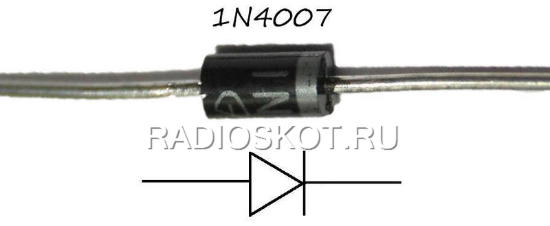
If there is no rectifier diode 1N4007
, then it can be replaced by 1N5399
or 1N5408
, which are designed for more high current. The gray circle on the diode represents its cathode.
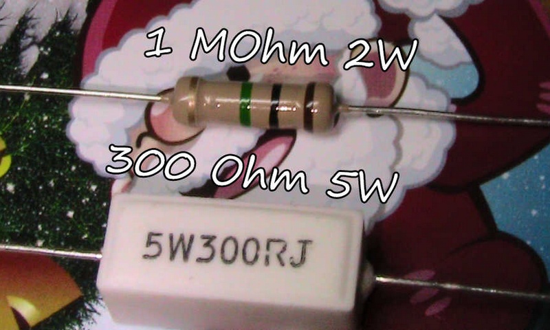
Resistor R1 was set to 5W, and R2 - to 2W, for insurance, although both could be used at 0.5 W.
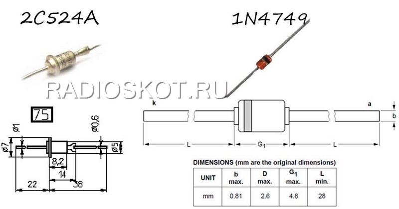
Zener diode BZV85C24
(1N4749), designed for a power of 1.5 W, and for a voltage of up to 24 volts, it can be replaced with a domestic one 2С524А
.
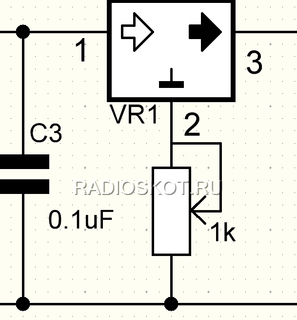
This transformerless power supply was assembled without adjusting the output voltage, but if you want to organize such a function, then simply connect a variable resistor of approximately 1 kOhm to pin 2 of the 78L08 microcircuit, and its second pin to the minus of the circuit.
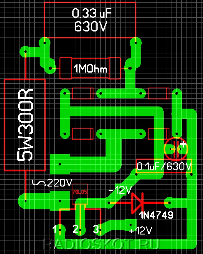
Of course, there is a board for the transformerless power supply circuit, it’s in Lay format, you can download it. I think you understand that diodes without markings are 1n4007
.
The finished structure must be placed in a plastic case, because the circuit connected to the network is under a voltage of 220 volts and under no circumstances should you touch it!
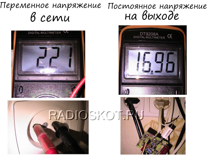
In these photos you can see the voltage at the input, that is, the voltage in the outlet, and how many volts we get at the output of the power supply.
Video of the operation of a transformerless power supply circuit
The big advantage of this scheme
The dimensions of the finished device can be considered very modest, because due to the absence of a transformer this power supply can be made small, and the cost of parts for the circuit is relatively inexpensive. Disadvantage of the scheme we can assume that there is a danger of accidentally touching a working source and receiving an electric shock. Author of the article - egoruch72.
Discuss the article TRANSFORMERLESS POWER SUPPLY OF CIRCUITS
At the very beginning of the topic, regarding the selection of a quenching capacitor, we will consider a circuit consisting of a resistor and a capacitor connected in series to the network. The total resistance of such a circuit will be equal to:
The effective current value, accordingly, is found according to Ohm’s law, the network voltage divided by the total resistance of the circuit:
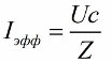
As a result, for the load current and input and output voltages we obtain the following relationship:
![]()
And if the output voltage is low enough, then we have the right to assume approximately equal to:
![]()
However, let's consider from a practical point of view the issue of selecting a quenching capacitor for connecting to an alternating current network a load designed for a voltage lower than the standard mains voltage.
Let's say we have a 100 W incandescent lamp rated at 36 volts, and for some incredible reason we need to power it from a 220 volt household network. The lamp requires an effective current equal to:
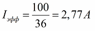
Then the capacity of the required quenching capacitor will be equal to:
Having such a lamp, we gain hope of getting a normal glow from the lamp; we hope that at least it will not burn out. This approach, based on the effective value of the current, is acceptable for resistive loads such as a lamp or heater.
But what to do if the load is nonlinear and connected through a diode bridge? Let's say you need to charge a lead-acid battery. What then? Then the charging current for the battery will be pulsating, and its value will be less than the effective value:
Sometimes a radio amateur may find it useful to have a power source in which a quenching capacitor is connected in series with a diode bridge, at the output of which there is, in turn, a filter capacitor of significant capacity, to which a load is connected direct current. It turns out a kind of transformerless power source with a capacitor instead of a step-down transformer:

Here the load as a whole will be nonlinear, and the current will no longer be sinusoidal, and calculations will need to be carried out somewhat differently. The fact is that a smoothing capacitor with a diode bridge and a load will outwardly manifest itself as a symmetrical zener diode, because the ripple with a significant filter capacitance will become negligible.
When the voltage on the capacitor is less than a certain value, the bridge will be closed, and if it is higher, the current will flow, but the voltage at the bridge output will not increase. Let's look at the process in more detail with graphs:
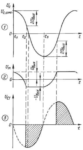
At time t1, the network voltage has reached amplitude, capacitor C1 is also charged at this moment to the maximum possible value minus the voltage drop across the bridge, which will be approximately equal to the output voltage. The current through capacitor C1 is zero at this moment. Then the voltage in the network began to decrease, the voltage on the bridge also, but on capacitor C1 it does not change yet, and the current through capacitor C1 is still zero.
Next, the voltage on the bridge changes sign, tending to decrease to minus Uin, and at that moment current flows through the capacitor C1 and through the diode bridge. Further, the voltage at the bridge output does not change, and the current in the series circuit depends on the rate of change of the supply voltage, as if only capacitor C1 was connected to the network.
When the network sinusoid reaches the opposite amplitude, the current through C1 again becomes equal to zero and the process goes in a circle, repeating every half period. Obviously, the current flows through the diode bridge only in the interval between t2 and t3, and the value of the average current can be calculated by determining the area of the patch under the sine wave, which will be equal to:
If the output voltage of the circuit is small enough, then this formula approaches the one obtained earlier. If the output current is set equal to zero, we get:
![]()
That is, if the load breaks, the output voltage will become equal to the amplitude of the mains voltage!!! This means that such components should be used in the circuit so that each of them can withstand the amplitude of the supply voltage.
By the way, when the load current decreases by 10%, the expression in parentheses will decrease by 10%, that is, the output voltage will increase by about 30 volts, if we are initially dealing with, say, 220 volts at the input and 10 volts at the output. Thus, the use of a zener diode in parallel with the load is strictly necessary!!!

What if the rectifier is half-wave? Then the current must be calculated using the following formula:
At small values of the output voltage, the load current will become half that of full bridge rectification. And the output voltage without load will be twice as high, since here we are dealing with a voltage doubler.
So, a power source with a quenching capacitor is calculated in the following order:
The first step is to choose what the output voltage will be.
Then the maximum and minimum load currents are determined.
If the load current is assumed to be variable, a zener diode in parallel with the load is required!
Finally, the capacitance of the quenching capacitor is calculated.
For a circuit with full-wave rectification, for a network frequency of 50 Hz, the capacitance is found using the following formula:

The result obtained from the formula is rounded towards the capacity of a larger nominal value (preferably no more than 10%).
The next step is to find the stabilization current of the zener diode for the maximum supply voltage and minimum current consumption:

For a half-wave rectification circuit, the quenching capacitor and the maximum zener diode current are calculated using the following formulas:
When choosing a quenching capacitor, it is better to focus on film and metal-paper capacitors. Film capacitors of small capacity - up to 2.2 microfarads for an operating voltage of 250 volts work well in these circuits when powered from a 220 volt network. If you need a large capacitance (more than 10 microfarads), it is better to choose a capacitor with an operating voltage of 500 volts or more.
Andrey Povny ( Google+ ,
Several circuits and calculations of transformerless power supplies with a quenching capacitor
Mains power supply with quenching capacitor(Fig. 1), in fact, is a voltage divider, the upper arm of which is a capacitor, and the lower arm is a complex nonlinear diode-resistor-capacitor circuit. This determines the disadvantages (and advantages, of course) of such devices.
Picture 1:
In order for the source to operate over a wide range of load current with high efficiency, it is enough to make the input voltage divider purely reactive, for example, a capacitor (Fig. 2).
Figure 2:
It allows you to additionally stabilize the output voltage of the source with a compensating or pulse stabilizer connected in series, which cannot be done in a conventional source with a quenching capacitor. As shown in the article by S. Biryukov “ Calculation of a network power supply with a quenching capacitor” - “Radio”, 1997, N 5, p. 48-50, - a series stabilizer can be used only if the voltage at its input is limited, which again significantly reduces the efficiency.
It is advisable to use a source with a capacitor voltage divider for joint operation with switching stabilizers. It is ideal for a device that consumes low current for a long time, but at some point requires a sharp increase in it. An example is an apartment watchdog device based on MOS microcircuits with an actuator unit based on a relay and an audible alarm.
The current consumed by the capacitor divider will have a phase shift of 90 degrees. relative to the mains voltage, so the voltage divider on reactive elements does not require cooling. Based on the above, it seems that the current through the divider can be chosen as large as desired. However, an unjustified increase in the divider current will lead to active losses in the wires and to an increase in the mass and volume of the device. Therefore, it is advisable to accept current through the voltage divider within 0.5...3 of the maximum load current.
Calculating a source with a capacitive divider is simple. As follows from formula (2) in the mentioned article, the output voltage Uout and total output current (zener diode and load Iout) source according to scheme 1, and are connected as follows:
Iout = 4fC1(2Uc-Uout)
This formula is also suitable for calculating a source with a capacitor divider; in it you just need to replace C1 with the total capacitance of parallel-connected capacitors C1 and C2, shown in Fig. 2. a Uc – on Uc2x (voltage on capacitor C2 at RH = °°), i.e.
Uc2x = Uc-C1/(C1+C2)
Then
Iout = 4f(C1+C2)x x
or after obvious transformations
Iout = 4f-C1
.
Since the voltage drop across the bridge diodes Ud at small values of Kout becomes noticeable, we finally get
Iout = 4f-C1 .
It is clear from the formula that at Рн=0 (i.e. at Uout=0), the current Iout, if we neglect the voltage drop across the diodes, remains the same as that of a power source assembled according to circuit 1,a. The output voltage without load decreases:
Uaux = =Uc-C1^/2/(C1+C2)-2Un.
The capacitance and operating voltage of capacitor C2 are selected based on the required output voltage - the ratio of capacitance values C1/C2 is inversely proportional to the values of the voltage falling on C1 and C2. For example, if C1″ = 1 µF, and C2 = 4 µF, then the voltage Uc1 will be equal to 4/5 of the network voltage, and Uc2 = Uc/5, which at a network voltage of Uc = 220 V corresponds to 186 and 44 V. It is necessary to take into account that the amplitude voltage value is almost 1.5 times higher than the effective one, and select capacitors for the corresponding rated voltage.
Despite the fact that theoretically capacitors in an AC circuit do not consume power, in reality they can generate some heat due to losses. You can check in advance the suitability of a capacitor for use in a source by simply connecting it to the mains and assessing the temperature of the case after half an hour. If capacitor C1 manages to warm up noticeably, it should be considered unsuitable for use in the source.
Special capacitors for industrial electrical installations practically do not heat up - they are designed for high reactive power. Such capacitors are used in fluorescent lamps, in ballasts of asynchronous electric motors, etc.
Below are two practical circuits of power supplies with a capacitor divider: a five-volt general purpose one (Fig. 3) for a load current of up to 0.3 A and an uninterruptible power supply for quartz electronic-mechanical watches (Fig. 4).
Figure 3:

Figure 4:
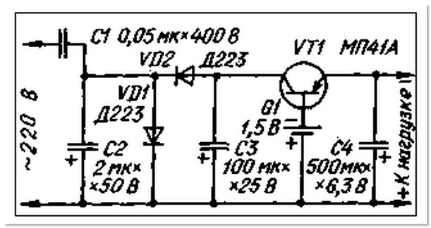
The voltage divider of a five-volt source consists of a paper capacitor C1 and two oxide capacitors C2 and SZ, forming the lower non-polar arm with a capacity of 100 μF in the circuit. The polarizing diodes for the oxide pair are the left-hand bridge diodes in the circuit. With the ratings of the elements indicated in the diagram, the circuit current (at Rн=0) is 600 mA, the voltage on capacitor C4 in the absence of load is 27 V.
Electronic-mechanical watches are usually powered by a single galvanic cell with a voltage of 1.5 V. The proposed source produces a voltage of 1.4 V with an average load current of 1 mA. The voltage removed from the divider C1C2 rectifies the node on the elements VD1, VD2. NW. Without load, the voltage on the capacitor SZ does not exceed 12V.

