Star News


The maximum allowable grounding resistance. Grounding norm how many ohms
C. Electrical safety Resistance of grounding devices (PUE-76, GOST 12.1.030-81)
Protective grounding provides, in systems with an isolated zero of the transformer, the discharge of current to the ground along the line of least "Resistance (compared to the resistance of the human body) through a metal conductor, firmly and tightly bolted to the body of the equipment, fencing. This conductor is connected to a grounding line, deeply grounded in the ground with special grounding conductors (pipes, plates).It is necessary to check more often the serviceability of grounding at workplaces in order to detect breaks, violations at the junctions in time.Once a year, a mandatory check of grounding resistance by equipment is carried out.In networks with voltages up to 1000 V, the resistance of grounding devices -
Inspection of the above-ground part of grounding devices electrical installations should be carried out simultaneously with the inspection of electrical equipment, but at least once a year. It is necessary to measure the resistance of grounding devices and check the presence of a grounding circuit with selective opening of individual elements of the grounding device at least once every 3 years, and also after rearranging the equipment.
The resistance of grounding devices should be measured during periods of the lowest conductivity: in summer - with the greatest drying, in winter - with the greatest freezing of the soil.
In electrical installations with high ground fault currents, the resistance of grounding devices at any time of the year should be no more than 0.5 ohm.
The resistance of the grounding device used to ground equipment with voltages above 1000 V should not exceed 10 ohms, and with high ground fault currents (over 500 A), the resistance of grounding devices should not exceed 0.5 ohms. .
Rules for the installation of electrical installations protective earth normalized by the value of its resistance. The greatest resistance of grounding devices in installations with voltage up to 1000 V depends on the power of the current source (generator or transformer). If the power of the current source is less than 100 kVA, then the grounding resistance is allowed to be 10 ohms; with a current source power of more than 100 kVA, the grounding resistance should be no more than 4 ohms. In electrical installations with voltages above 1000 V with high earth fault currents (more than 500 A), the resistance of the ground gel should not exceed 0.5 Ohm. In installations with voltages above 1000 V with low earth fault currents, the resistance of the earth electrode is determined by the ratio 250//3; if the grounding device is simultaneously used for electrical installations up to 1000 V, then the resistance of the ground electrode should not exceed 125//3, but should not exceed 10 ohms (or 4 ohms if required for installations up to 1000V). Here /z is the earth fault current.
The resistance of earthing devices in explosive rooms and outdoor installations should only be measured with explosion-proof instruments designed for the respective explosive atmospheres. As a rule, the resistance to current spreading is
With a loop (distributed) ground electrode, when the resistance of the ground conductors is usually small, the resistance of the grounding device K3.y can be considered equal to R3- , and D3,y In this case, the impedance of the grounding device, Ohm,
Re-grounding of the neutral wire must be carried out at the ends of branches of overhead lines with a length of more than 200 m and in the middle of a line and branch with a length of 500 m. 4 and 8 ohms, respectively, at line voltages of 66U, 380 and 220V of a three-phase current source or 380, 220 and 127 V of a single-phase current source.
Metallic and electrically conductive parts of process equipment must be grounded to prevent sparking of static electricity. The resistance of grounding devices should not exceed 100 ohms.
1 - transformer; 2 - network; 3 - body of the current collector; 4 - motor winding; 5 - ground electrode; 6 - neutral grounding resistance (conditionally)
/ - transformer; 2 - network; 3 - fuse; 4 - motor winding; 5 - motor housing; 6 - grounding conductor; 7 - zero protective conductor; 8 - neutral earthing resistance
In the presence of grounding, due to current draining to the ground, the contact voltage decreases and, therefore, the current passing through a person is less than in an ungrounded installation. In order to minimize the voltage on the grounded equipment case, the ground resistance is limited. In 380/220 V installations, it should be no more than 4 ohms, in 220/127 V installations, no more than 8 ohms. If the power supply capacity does not exceed 100 kVA, the ground resistance can be within 10 ohms.
resistance of grounding and isolation of phases. With good insulation, gf is equal to tens of kΩ, so the current / s will be small. So, with a phase voltage of 220 V g, \u003d 4 Ohm, /F \u003d 40,000 Ohm, L \u003d 220 / (4 + +40,000) \u003d 0.0055 A. The potential drop will be distributed as follows: on the ground - between the case and the base U3 \u003d / Eg3 \u003d \u003d 0.0055-4 \u003d 0.022 V, between the base and the phases (potential drop on the insulation
In a network with a grounded neutral (see Fig. 7.5, 6) 13 \u003d U $ / (r3 + /b) \u003d \u003d 220 / (4 + 10) \u003d 15.7 A (/b is the electrical resistance of neutral grounding, usually not exceeding 10 ohms), and the touch voltage? / pr \u003d U3 \u003d 15.7 4 \u003d 62.8 V, which is dangerous for humans. As can be seen, in this case, 13 increases significantly with decreasing r, and the grounding efficiency is low. The lower the electrical resistance of the grounding of the installation case in comparison with the neutral grounding resistance, the higher the protective properties of the grounding will be.
According to the PUE, the electrical resistance of protective grounding at any time of the year should not exceed: 4 ohms in installations with voltages up to 1000 V with isolated neutral (with a current source power - generator or transformer - less than 100 kW, no more than 10 ohms is allowed). In installations with a grounded neutral, the ground resistance is determined by calculation based on the requirements for the allowable contact voltage, but not more than 0.5 Ohm.
Installations for the application of powder polymer paints must be equipped with local exhaust ventilation interlocked with the powder supply system, as well as devices that prevent sparking when the sprayer approaches the product to be painted due to static electricity discharges. To eliminate spark discharges of static electricity, it is necessary to ground the suspension of the product. Ground resistance should not exceed 1C6 ohm; it is subject to control at least once a shift.
During a scheduled inspection of the compressor unit, the following should be checked: the compressor and its motor; serviceability of the lubrication system; safety valves, pressure gauges; tightening degree of bolted connections; electrical insulation resistance and grounding resistance; operation of automatic devices; condition of check valves. Scheduled inspections should be carried out according to a schedule drawn up taking into account the recommendations of the manufacturer.
neutral grounding resistance (for networks with grounded neutral) (Fig. 39, biv). If the value of the insulation resistance of the network is large, then in practice the current passing through the person is very small, and in this case the network with a line voltage of the network U up to 1000 V is relatively safe with a single-phase connection.
Grounding conductors connect the electrical equipment housings to the grounding conductor. Overhead cranes, except those operating in an explosive atmosphere, are grounded through the crane runway. Grounding resistance in networks with an operating voltage of up to 1000 V, which include electric taps, should not exceed 4 ohms along with the loop resistance.
When checking grounding, keep in mind that the grounding resistance should not exceed 4 ohms. The witness must familiarize himself with the results of the resistance measurement.
Elmashprom LLC produces ready-made grounding and lightning protection kits for station and linear structures of wire communication installations, radio relay stations, wire broadcasting (PV) radio broadcasting units, selective railway communication installations and antennas of collective television reception systems, which include: rod prefabricated lightning rods up to 25 meters high (for buildings and structures on brackets and free-standing), deep vertical grounding switches, horizontal grounding conductors, clamps for connecting grounding conductors, holders for fastening the leads of grounding conductors, holders for installing a potential equalization system, main grounding buses, flexible grounding conductors, welded grounding contacts, etc. Technical solutions and fasteners for designers in DWG.
NORMS OF RESISTANCE GOST 464-79
Moscow
STATE STANDARD OF THE UNION OF THE SSR
Introduction date 01.01.80
This standard applies to (SKPT), for which stationary grounding devices are equipped, and establishes the resistance standards for grounding devices that ensure the normal operation of the structures and installations listed above, as well as the safety of maintenance personnel.
The standard does not apply to grounding devices that are provided in special-purpose equipment.
The terms used in this International Standard and their definitions are given in the annex.
1. GENERAL PROVISIONS
1.1. To the working protective or protective earthing device by means of grounding wires, the shortest way must be connected:
one of the poles of the power supply installation;
the neutral of transformers, the output of a single-phase current source of a transformer substation or its own power plant supplying equipment of communication enterprises, a radio relay station or a PV station;
metal parts of power, static and switching equipment;
metal reference equipotential surface of electronic telephone exchanges;
metal pipelines for water supply and central heating and other metal structures inside the building;
screens of equipment and cables;
metal sheaths of cables, elements of protection circuits, lightning rods;
SKPT antennas subject to lightning protection in accordance with regulatory and technical documentation (hereinafter RTD).
The number of ground wires and the procedure for connecting equipment and equipment to them are established in the NTD for equipment of a particular type.
(Revised edition, Rev. No. 2).
1.2. Communication facilities should be equipped with protective earthing device, if there are no connecting lines and remote power supply circuits for equipment using earth as a wire electrical circuit.
Requirements to protective grounding and zeroing- according to GOST 12.1.030.
(Revised edition, Rev. No. 1).
1.3. Communication facilities should be equipped with one working and protective grounding device, if the "minus" of the remote power supply is grounded (in this case, the remote power supply circuits can be switched on according to the "wire-to-ground" scheme) or the "plus" of the current source is grounded, but there are no remote power supply circuits according to the "wire-to-ground" scheme. In this case, the connecting lines can use the "ground" as the wire of the electrical circuit. The circuit of the working-protective grounding device, in the presence of remote power supply circuits, must have two independent inputs to the building (up to the ground shield).
Enterprises should equip separate working and protective grounding devices if there are remote power supply circuits according to the "wire-ground" scheme with grounding "plus" of the current source.
1.4. The neutral of the transformers, the output of the single-phase current source of the transformer substation or its own power plant that supplies the equipment of communication enterprises, a radio relay station or a PV station, must be connected to a protective or working and protective grounding device. In this case, the grounding device for the above enterprise and for the transformer substation must be common if the distance between the enterprise and the transformer substation is less than 100 m.
Common ground resistance must comply with the grounding device resistance standards for each connected installation.
Resistance grounding device, to which the neutrals of generators or transformers or the output of a single-phase current source are connected, with a soil resistivity of up to 100 Ohm m, there should not be more than, Ohm:
2 - installations with a voltage of 660/380 V;
4 - installations with a voltage of 380/220 V;
8 - installations with voltage 220/127 V.
When the specific soil resistance r is more than 100 Ohm m, it is allowed to increase the resistance value of the grounding device by r / 100 times, but not more than ten times, and also not more than the values \u200b\u200bspecified in Table. Table 1-Table 3, Table 5 and in paragraphs. Clause 2.1.5, Clause 2.4.5, Clause 2.7.2.
1.3, 1.4. (Revised edition, Rev. No. 2).
1.4a. The resistance of a protective or working-protective grounding device must be ensured taking into account the use of natural grounding conductors (metal pipes laid underground, metal structures, reinforcement of buildings and their concrete foundations, etc., with the exception of pipelines of combustible and explosive mixtures, sewerage, central heating and domestic water supply located outside the building in which the equipment of the communication enterprise or the PV station is located).
1.5. The design of artificial ground electrodes or various circuits of the grounding device, the brand and cross section of the connecting conductors from the grounding device to the ground shield, the list of equipment, equipment and protection elements connected to the grounding device, the methods of connecting wires and their number, the method for measuring the resistance of grounding devices and soil resistivity set in the NTD for equipment of a particular type.
(Revised edition, Rev. No. 2).
1.6. The distance between individual non-insulated parts of different grounding devices (between working, protective, measuring, etc.) in the area before entering the building should not be less than 20 m.
1.7. The resistance of the measuring grounding device should not be more than 100 Ohm in soils with a resistivity of up to 100 Ohm m and 200 Ohm in soils with a resistivity of more than 100 Ohm m.
1.8. Resistance of linear-protective grounding devices for communication lines and wire hanging in areas of dangerous influence of power lines, electrified railways, as well as under the influence of radio stations and impulse effects (excluding lightning discharges), determined by calculation in accordance with the requirements of the NTD, should not exceed the values established by this standard.
(Revised edition, Rev. No. 2).
1.9. During the operation of grounding devices, their resistances should be checked at intervals:
twice a year - in summer (during the period of the greatest drying of the soil) and in winter (during the period of the greatest freezing of the soil) - at intercity, urban and rural telephone stations, telegraph stations, telegraph broadcasting, terminal and subscriber points;
once a year - in the summer (during the period of the greatest drying of the soil) - at radio relay stations, at stations and substations of radio broadcasting nodes;
once a year - before the beginning of the thunderstorm period (April - May) - in unattended amplification points (NUP) and regeneration points (RP) of long-distance, urban and rural communications; for containers of equipment of transmission systems (IKM-30, etc.);
once a year - before the start of the thunderstorm period - on cable and overhead communication lines and radio broadcasting networks, at cable poles and poles on which protective equipment is installed, at subscriber stations of telephone and radio broadcast networks, at step-down transformers of payphone booths;
at least once a year (before the beginning of the thunderstorm period) - for antennas of collective television reception systems.
2. STANDARDS OF RESISTANCE
2.1. Resistance standards of grounding devices for intercity telephone exchanges and terminal points of selective railway communication
2.1.1. Intercity telephone exchanges (MTS), end points of selective railway communication, linear equipment shops (LATS) and intermediate amplifying points with power supply installations must be equipped with a protective or working-protective grounding device and two measuring grounding devices. When equipping a working and protective grounding device in accordance with clause 1.3, one measuring grounding device is arranged, which must be connected in parallel with the protective grounding device.
In working condition, the measuring grounding devices must be connected on the grounding shield in parallel with the protective or working-protective grounding devices.
2.1.2. The resistance of protective grounding devices of MTS, linear equipment shops and intermediate amplifying points, as well as terminal points of selective railway communication with power supply installations that do not use earth as a current conductor in the circuits of connecting lines or remote power supply of unattended amplifying and regeneration points according to the “wire- earth”, should be no more than the values specified in clause Clause 1.4.
2.1.3. The resistance of protective grounding devices of intermediate points that do not have power supply installations should be no more than 10 Ohm for soils with a resistivity of up to 100 Ohm m and no more than 30 Ohm for soils with a resistivity of more than 100 Ohm m.
2.1.4. The resistance of working or working-protective grounding devices of MTS using earth as one of the wires of connecting lines of any type (custom, service from MTS and ATS, transit service lines, etc.), or in remote power supply circuits (DP) should not exceed the values indicated in the table. Table 1, and working and protective grounding devices must also comply with the requirements of clause 1.4.
Table 1
(Revised edition, Rev. No. 2).
2.1.5. Resistance of working or working-protective grounding devices of linear hardware shops, strong points; serviced amplifying points supplying remotely unserved or regeneration points according to the “wire-to-ground” scheme should be determined based on the voltage drop on the grounding device from the remote supply current of not more than 12 V. However, the resistance of working or working-protective grounding devices should not be more than the values specified in clause Clause 1.4.
2.1.6. Serviced amplification points of submarine cable lines that remotely feed underwater amplifiers according to the “wire-to-ground” scheme must be equipped with two separate working grounding devices (main and backup), which must be connected at the ground shield when in operation. The resistance of the main working grounding device should be no more than 5 ohms and the reserve - no more than 10 ohms.
(Introduced additionally, Amendment No. 2).
2.2. Resistance standards of grounding devices for unattended amplifying points of long-distance communication and intermediate points of selective railway communication
2.2.1. Unattended amplifying points (NUP), powered remotely according to the "wire-ground" scheme, in which the remote power supply circuit ends, must be equipped with three separate grounding devices - working, protective and linear-protective.
As a protective grounding device, it is allowed to use magnesium protectors used to protect metal tanks of LLP from soil corrosion.
In cases where it is not required to protect LLP metal tanks from soil corrosion, as well as when using non-metallic hulls, LLP must be equipped with a working and combined protective grounding device.
2.2.2. Unattended amplifying points (NUP) and regeneration points (RP) powered remotely according to the “wire-wire” scheme, as well as NUP fed according to the “wire-to-ground” scheme, in which the remote power circuit does not end, must be equipped with two separate grounding devices - protective and linear-protective.
As grounding conductors for a protective grounding device, it is allowed to use magnesium protectors used to protect metal tanks of LNP or RP from soil corrosion.
In cases where it is not required to protect metal LLP or RP tanks from corrosion, as well as when non-metallic LNP or RP tanks are used, a combined protective grounding device must be equipped.
2.2.3. The resistance of the working grounding device for NUP fed according to the "wire-ground" scheme should be no more than 10 Ohm for soils with a resistivity of up to 100 Ohm m and no more than 30 Ohm for soils with a resistivity of more than 100 Ohm m. In this case, the voltage drop from remote supply currents on the resistance of the grounding device should be no more than 12 V for soils with a resistivity of up to 100 Ohm m and no more than 36 V for soils with a resistivity of more than 100 Ohm m.
2.2.4. The resistance of protective grounding devices for NUP or RP fed according to the "wire-ground" and "wire-wire" schemes should be no more than 10 Ohm for soils with a resistivity of up to 100 Ohm m and no more than 30 Ohm - for soils with a specific with a resistance of more than 100 ohm m.
2.2.5. The resistance of line-protective grounding devices for cable sheaths, equipped at NUP or RP, when protecting cables from lightning strikes, should not exceed, Ohm:
10 - for soils with resistivity up to 100 Ohm m inclusive;
20 - for soils with specific resistance of St. 100 to 500 Ohm m incl.;
30 - for soils with specific resistance of St. 500 to 1000 Ohm m incl.;
50 - for soils with specific resistance of St. 1000 ohm.m.
(Revised edition, Rev. No. 2).
2.2.6. Intermediate points of selective railway communication must be equipped with one protective grounding device, the resistance of which must not exceed the values \u200b\u200bspecified in Table. Table 2.
table 2
2.3. Norms of resistance of grounding devices for telegraph stations and telegraph broadcasting terminals and subscriber points.
2.3.1. Telegraph stations, broadcasting, terminal and subscriber points operating on two-wire circuits, located in a separate building (not combined with MTS, ATS and other enterprises) and not using the "ground" as a wire of an electrical circuit, must be equipped with a protective and two measuring grounding devices. In working condition, all grounding devices must be connected in parallel on the grounding plate. Telegraph stations, broadcasting terminals and subscriber points combined with other enterprises (MTS, ATS) must include ground wires to a common protective grounding device.
For telegraph stations, where up to five telegraph sets are installed, it is allowed to use temporary measuring grounding devices.
2.3.2. The resistance of the protective grounding device of telegraph stations with power supply installations should not exceed the values \u200b\u200bspecified in clause Clause 1.4.
Broadcasting, terminal and subscriber points that do not have power supply installations must be equipped with a protective grounding device with a resistance of not more than 10 ohms with a specific soil resistance of up to 100 ohm m and 20 ohm for soils with a specific resistance of more than 100 ohm m.
2.3.3. Telegraph stations and telegraph broadcasting points operating on single-wire circuits must be equipped with a working-protective and two measuring grounding devices. For telegraph stations, where up to five telegraph sets are installed, it is allowed to use temporary measuring grounding devices.
The resistance of the working-protective grounding device, depending on the number of single-wire telegraph circuits introduced into the station (see GOST 5238, drawings 26-31), should not exceed the values \u200b\u200bspecified in Table. Table 3
Table 3
2.4. Resistance standards for grounding devices for city telephone exchanges and local railway stations
2.4.1. Telephone exchanges with a central battery (automatic exchanges and manual - PTS) must be equipped with three separate grounding devices - protective or working-protective and two measuring.
In working condition, all three grounding devices must be connected in parallel on the grounding shield and are disconnected only to measure the resistance of the protective or working-protective grounding device.
2.4.2. Telephone exchanges that have connecting lines and do not use earth as a current conductor (for example, connecting lines equipped with inductive sets of the RSL type) should be equipped with protective grounding devices (clause 1.2), the resistance of which should not exceed the values \u200b\u200bspecified in clause 1.2. 1.4.
Telephone exchanges without power transformer substations powered by electrical networks voltage 380/220/127 V, must be equipped with a protective grounding device with a resistance not exceeding the values \u200b\u200bspecified in Table. four.
Table 4
(Revised edition, Rev. No. 2).
2.4.3. Telephone exchanges with connecting lines using earth as current conductors (according to clause 1.3) must be equipped with working and protective grounding devices, the resistance of which must not exceed the values \u200b\u200bspecified in Table. 5.
Table 5
Note. In cases where at the station the connecting lines are equipped with inductive and battery (using earth as a current conductor) sets of the RSL type, the value of the resistance of the working and protective grounding is selected depending on the number of battery (polar) sets of the RSL type.
2.4.4. Unattended amplifying and regenerating points, fed remotely according to the "wire-wire" and "wire-ground" schemes, must be equipped with one protective grounding device, the resistance value of which must correspond to that given in clause 2.2.4.
2.4.5. The resistance of the protective or working-protective grounding device of electronic telephone exchanges must be no more than 4 ohms, and also comply with the requirements of paragraphs. 2.4.2 and 2.4.3.
(Introduced additionally, Amendment No. 2).
2.5. Resistance standards for grounding devices of rural telephone exchanges (STS)
2.5.1. Rural telephone exchanges with a central battery (RTS and ATS) must be equipped with three separate grounding devices in accordance with paragraphs. 2.4.1-2.4.3.
2.5.2. It is allowed to equip telephone exchanges with a capacity of up to 3000 numbers with one protective or working-protective grounding device, and temporary grounding devices can be used as measuring grounding devices.
(Revised edition, Rev. No. 2).
2.5.3. For compaction equipment of rural exchanges and RTSs, in the case of using the power supply system of the NUP "wire-wire", one combined protective grounding device should be used. At the same time, unattended amplifying points must be equipped with protective grounding devices with a resistance not exceeding the values \u200b\u200bspecified in paragraphs. 2.1.2 and 2.1.3.
2.5.4. Unattended amplifying points fed remotely according to the "wire-ground" scheme should be equipped with two separate grounding devices: working and linear-protective. The resistance of working and linear protective grounding devices should be no more than the values \u200b\u200bspecified in paragraphs. 2.2.3 and 2.2.5.
2.6. Ground resistance standards for telephone exchanges with a local battery (MB)
2.6.1. Telephone exchanges of the MB system operating on two-wire circuits must be equipped with three separate grounding devices - protective and two measuring. In working order, these three earthing devices must be connected in parallel at the earthing board. With a station capacity of up to 200 numbers, it is allowed not to equip stationary measuring grounding devices, and when measuring a protective grounding device, use temporary grounding devices.
2.6.2. The resistance of the protective grounding device of MB stations operating in two-wire circuits should not exceed the values \u200b\u200bspecified in Table. 2.
2.7. Resistance standards for grounding devices for stations and PV
2.7.1. Stations and PV should be equipped with one protective or working-protective grounding device. For control measurements of the resistance of the protective and working-protective grounding device, it is allowed to equip two stationary measuring grounds or use temporary grounding devices.
2.7.2. The resistance of a protective or working-protective grounding device for PV stations should be no more than 10 ohms.
2.7-2.7.2. (Revised edition, Rev. No. 2).
2.7.3. PV stations and transformer substations feeding them, geographically close to one another (clause 1.4), should be equipped with a common protective or working-protective grounding device with a resistance of not more than the values \u200b\u200bspecified in clause 1.4.
(Introduced additionally, Amendment No. 2).
2.8. Resistance standards of grounding devices for combined installations of wire communication and PV
(Revised edition, Rev. No. 2).
2.8.1. Stationary installations of wire communication for various purposes, located in one or nearby buildings and powered by one transformer substation: long-distance, urban, railway selective communications and others, as well as stations and substations of radio broadcasting nodes, should be equipped with one common protective or working protective grounding device . In this case, the resistance of the connecting wires from the grounding device should be taken into account.
2.8.2. The resistance value of the common earthing device must comply with the regulations for each connected installation.
2.8.3. Not allowed in unattended amplification points powered remotely direct current, combine a common protective grounding device with a working one.
2.9. Resistance standards for protective grounding devices for long-distance communication lines
2.9.1. Grounding device resistance values for:
spark gaps of cascade protection types IR-7, IR-10, IR-15 and IR-20;
spark gaps IR-0.2 or IR-0.3 - when they are installed on supports adjacent to the cable support or station;
spark gaps installed on the wires of overhead lines to protect underground communication cables from lightning strikes;
lightning rods installed on the supports of overhead lines;
rope and metal sheaths of cables suspended on overhead line supports should be no more than the values \u200b\u200bspecified in Table. 6.
Table 6
(Revised edition, Rev. No. 2).
2.9.2. The resistance of protective grounding devices for input, cable and other supports of long-distance communication lines and selective railway communication, on which, in accordance with the requirements of GOST 5238, it is required to include spark gaps of types IR-0.2 and IR-0.3 or gas-filled arresters, must not be more than the values indicated in the table. 7.
Table 7
2.9.3. The resistance of protective grounding devices for arresters of the IR-0.3 type, included to protect locking coils in the third circuits (see GOST 5238, drawing 9), should not exceed the values \u200b\u200bspecified in Table. 6.
2.9.4. The resistance of linear protective grounding devices for metal cable sheaths, protective wires (cables) or tires laid in the ground when protecting the cable from lightning strikes should not exceed the values \u200b\u200bspecified in Table. eight.
Table 8
Note. The number of linear protective grounding devices, their placement on cable lines and the method of connecting metal sheaths, cables and cable screens are established in the regulatory and technical documentation.
2.10. Resistance standards for protective grounding devices for urban and rural telephone networks and local railway networks
2.10.1. Resistance of grounding devices for spark gaps of types IR-0.2; IR-0.3; IR-7; IR-10 and IR-15, attached according to the schemes of features. 19, 22-24 GOST 5238, should be no more than the values \u200b\u200bspecified in table. 6.
2.10.2. Resistance of grounding devices for gas-filled arresters of R-84 and R-35 types installed in cable boxes at the junctions of wires of overhead lines of GTS, STS and railway communication networks with cable lines (see GOST 5238, drawings 15-17; 21a), a also for installation points of blockers (see GOST 5238, drawing 24), should be no more than the values \u200b\u200bspecified in Table. 9.
Table 9
Soil resistivity, Ohm m Up to 100 incl. St. 100 to 300 incl. St. 300 to 500 incl. St. 500
Resistance of grounding devices, Ohm, no more than 10 15 20 25
(Revised edition, Rev. No. 2).
2.10.3. The resistance of grounding devices for subscriber stations (see GOST 5238, drawings 16, 17, 21), for step-down transformers of payphone booths and lightning rods installed on overhead line supports, should not exceed the values \u200b\u200bspecified in Table. ten.
Table 10
Soil resistivity, Ohm m Up to 100 incl. St. 100 to 300 incl. St. 300 to 500 incl. St. 500 to 1000 inclusive St. 1000
Grounding device resistance, Ohm, no more than 30 45 55 65 75
2.10.4. Resistance of grounding devices for the metal sheath of the cable, the screen of the cable with non-metallic sheaths when suspended on the supports of pole and rack lines, the rope used for hanging cables, as well as for the housing of telephone distribution cabinets type ShR or ShRP, which include cables, should be no more than the values \u200b\u200bspecified in Table. 6.
2.10.5. The resistance of linear protective grounding devices for protection against lightning strikes of GTS and STS cables laid in the ground, as well as for the case of telephone switchboards of the ShR and ShRP types, which include cables, should not exceed the values \u200b\u200bspecified in Table. eight.
2.11. Resistance standards of protective grounding devices on PV lines
2.10.4, 2.10.5, 2.11. (Revised edition, Rev. No. 2).
2.11.1. Resistance of linear protective grounding devices for spark gaps of types IR-0.5 and IR-7.0 (see GOST 14857, drawings 1, 2), as well as for arresters of types IR-0.3 and IR-7.0 (see GOST 14857, drawings 3, 5, 6) should be no more than the values \u200b\u200bspecified in table. 6.
2.11.2. Resistance of linear protective grounding devices for grounding the metal sheath and screen of cables laid in channels cable duct and collectors (at the beginning and at the end of the cable) should be no more than the values \u200b\u200bspecified in Table. eight.
2.11.3. The resistance of linear protective grounding devices for lightning rods installed on the poles of overhead power lines should not exceed the values \u200b\u200bspecified in Table. ten.
(Revised edition, Rev. No. 2).
2.12. Resistance standards for grounding devices for radio relay stations
2.12.1. Radio relay stations, including those with compaction equipment, must be equipped with one protective grounding device. To control the resistance of the protective grounding device, it is allowed to equip two stationary measuring grounding devices or use temporary grounding devices. In working condition, protective and measuring stationary grounding devices must be connected in parallel on the grounding board.
2.12.2. The resistance of the protective grounding device must not exceed the values specified in clause 1.4.
2.13. Resistance standards of grounding devices for antennas of the collective television reception system
2.13.1. To protect the SKIT antennas from dangerous voltages and currents arising from lightning discharges, a protective grounding device must be equipped. To control the resistance of the protective grounding device, it is allowed to use temporary measuring grounding devices.
2.13.2. It is allowed to connect lightning rods from two or more SKPT antennas located on the same building to one grounding device.
2.13.3. The design of the grounding device, as well as the lightning rod connecting the SKPT antenna to the grounding device, and the method of their connection are established in the regulatory and technical documentation.
2.13.4. The resistance of the grounding device for SKPT antennas should be no more than the values \u200b\u200bspecified in Table. 6.
2.13.5. If there is a grounding device for the building on which the SKPT antennas are located (when protecting buildings from lightning strikes or for protecting telephone communication and broadcasting equipment), it is allowed to connect lightning rods from the SKPT antennas to the existing grounding device. The resistance of the grounding device should be no more than the values \u200b\u200bspecified in Table. 6.
APPENDIX
Reference
TERMS USED IN THIS STANDARD AND THEIR DEFINITIONS
Term Definition
Grounding for wired communication installations, radio relay stations, PV radio broadcasting nodes, etc. Intentional electrical connection of equipment or apparatus of an enterprise with a grounding device
Grounding conductor A metal conductor or a group of conductors of any shape (pipe, angle, wire, etc.) in direct contact with the ground (soil)
Grounding conductor A metal conductor that connects equipment or equipment to be grounded to the grounding conductor.
Grounding device A combination of ground electrode and ground conductors
Grounding device resistance or current spreading resistance The total electrical resistance of the grounding conductors and the grounding conductor relative to the ground, expressed in ohms. The resistance of the earth electrode relative to the earth is defined as the ratio of the voltage of the earth electrode relative to the earth to the current passing through the earth electrode to the ground
Soil resistivity The electrical resistance exerted by soil with a volume of 1 m3 when current flows from one face of the soil to the opposite. Soil resistivity, denoted by r and expressed in ohms per meter, should be measured seasonally, taking the most unfavorable value as the design
Working grounding device A device designed to connect wired communication equipment and radio engineering devices (PV substations, radio relay stations) to the ground in order to use the earth as one of the wires of the electrical circuit
Protective grounding device A device designed to connect neutral wires of the windings of power transformer substations, lightning rods, arresters, screens of equipment and wires for in-station installation, metal sheaths and armored covers of cables, metal tanks, maintenance-free amplifying points (NUP), metal parts of power equipment of wired installations communication and PV stations, installations for keeping cables under pressure and other equipment that is not normally energized, but may become energized if the insulation of current-carrying wires is damaged. Protective grounding devices provide equalization of the potential of the metal parts of the equipment with the ground potential and thus protect the operating personnel and equipment from the occurrence of a dangerous potential difference with respect to the ground.
Linear protective grounding device A device that provides grounding of cable metal sheaths and armored covers along the cable route and at stations (NUP) where cable lines are suitable, as well as on overhead lines for grounding lightning rods, cables and metal sheaths of the cable, etc. In some cases, it is allowed to combine protective and linear protective grounding devices. Such a grounding device is called a combined protective
Measuring grounding device Auxiliary device designed for control measurements of the resistance of working, protective and working-protective grounding devices. The resistance of the working and protective grounding devices should be measured, as a rule, from the grounding shield at the station, including the grounding conductor towards the grounding conductor. The resistance of grounding devices on overhead and cable lines is measured directly on the line
Working and protective grounding device A device that simultaneously serves as both a working and protective grounding device. The resistance of the working and protective grounding device must be no more than the smallest value provided for the working and protective grounding devices.
(Revised edition, Rev. No. 2).
INFORMATION DATA
1. DEVELOPED AND INTRODUCED by the Ministry of Communications of the USSR
DEVELOPERS:
A.K. Slanov (topic leader); V.V. Zakharov
2. APPROVED AND INTRODUCED BY Decree State Committee USSR according to the standards of 29.01.79 No. 304
3. The standard is unified with BDS 4722-70
4. Periodicity of inspection - 5 years
5. REPLACE GOST 464-68
6. REFERENCE REGULATIONS AND TECHNICAL DOCUMENTS
7. The limitation of the validity period was removed according to protocol No. 4-93 of the Interstate Council for Standardization, Metrology and Certification (IUS 4-94)
8. REPUBLICATION (October 1997) with Amendments No. 1, 2, approved in December 1983, June 1989 (IUS 4-84, 10-89)
Page 1
The resistance value of the grounding device on the 0-4 kV side should be 4 ohms. This resistance must also be accepted for the 6 kV side with a common ground.
The value of the resistance of the grounding device r3 in comparison with the resistance of the human body Kchsya is very small: according to the norms, it should not exceed 4 ohms.
The resistance value of the grounding device of a mobile electrical installation must be checked during its construction, as well as during the next technical services. If natural grounding conductors are also used to reduce the resistance of artificial grounding conductors in an electrical installation, then the measurement of their resistances must be carried out separately. Only if it is not possible to separate artificial ground electrodes from natural ones, is it possible to measure the total resistance.
The resistance value of the grounding device normalized by the PUE depends on the ground fault current, the installation voltage and the method of grounding the neutrals of transformers or generators of the network in question.
At the same time, the value of the resistance of the grounding device (R) should be no more than 4 ohms. As an exception, at transformer substations with one transformer with a capacity of 100 kVA or less, the grounding device may have a resistance of not more than 10 ohms.
It is equivalent to limiting the value of the resistance of the grounding device and, consequently, the voltage in relation to the earth to some valid value. As such a resistance value of the grounding device in the Rules, 4 ohms are accepted.
To obtain the resistance value of the grounding device required by the norms, in addition to the circuits, beam ground electrodes are laid.
As you can see, with this method, the value of the resistance of the grounding device is not limited, and safety must be achieved by equalizing the potentials.
The first condition is to a certain extent satisfied by the requirement of the Rules on the value of the resistance of the grounding device is not more than 4 ohms. This is also facilitated by the presence of repeated grounding of the neutral wire.
Artificial grounding conductors are used in cases where there are no natural grounding conductors near the electrical installations to be grounded, or when, after using natural grounding conductors, the resistance value of the grounding device does not meet the standards or design requirements.
In soils with higher resistivity, the natural conductivity of reinforced concrete foundations, supports and stepchildren should not be taken into account, and the required table. P-5-14, the resistance value of the grounding device should be ensured only by the use of artificial grounding conductors.
The design resistance of the grounding device is determined. The value of the resistance of the grounding device is determined depending on the purpose and in all cases is regulated by the Electrical Installation Rules. The resistance of the grounding device in networks up to 1,000 V should not exceed 4 ohms, and with a power of generators or transformers of 100 kVA or less - 10 ohms.
The design resistance of the grounding device is determined. The value of the resistance of the grounding device is determined depending on the purpose and in all cases is regulated by the Electrical Installation Rules. The resistance of the grounding device in networks up to 1000 V should not exceed 4 ohms, and with a power of generators or transformers of 100 kVA or less - 10 ohms.
Hello dear site visitors.
Today we will find out what grounding device resistance meets the requirements of regulatory documents.
So, in the last article, we looked at how to properly install. But each ground loop has its own resistance requirement.
Grounding device resistance, it is also called the spreading resistance of electric current - this is a value that is directly proportional to the voltage on the grounding device, and inversely proportional to the spreading current to the "ground".
The unit of measure is Ohm.
And the smaller this value, the better. Ideally, the resistance of the grounding device should be zero. But it is simply impossible to achieve such resistance in reality.
And as always, according to the standards of grounding resistance, let's turn to the regulatory document, to chapter 1.7.

PUE. Section 1. Chapter 1.7.
For each electrical installation and its voltage level, the PUE are clearly defined.
In this article, we will consider the resistance standards of only those electrical installations that are of interest to us, i.e. household voltage 380 (V) and 220 (V).
The above standards for the resistance of grounding devices refer to soils that are ideal for mounting a ground loop (clay, loam, peat).
P.S. And for dessert, an interesting video ...
57 comments on the entry “Resistance of the grounding device”
Great site!
I really like to delve into wires and sockets, but I don’t understand much about it, only the basic basics. Now I will visit your site more often, it is very useful.
Thank you. Great article.
I will be glad to see you at my place.
My husband is doing this, he is an electrical engineer by profession. Who will benefit from your article, thanks!
Everything is simple and clear even to me!
You wrote in the previous article "How to independently measure the ground loop (grounding device) I will write in the next article.". Very necessary information. I would like to see this information.
Today I plan to write this article ...
Measurements are taken by specialists. With a license. Without equipment, appropriate knowledge, it is not realistic to do it yourself.
The above paragraph of the PUE 1.7.101. concerns the source of electricity, the consumer, in my opinion, needs to use the following item:
1.7.103. The total spreading resistance of ground electrodes (including natural ones) of all re-groundings of the PEN conductor of each overhead line at any time of the year should be no more than 5, 10 and 20 Ohms, respectively, at line voltages of 660, 380 and 220 V of a three-phase current source or 380, 220 and 127 V single-phase current source. In this case, the spreading resistance of the grounding conductor of each of the repeated groundings should be no more than 15, 30 and 60 ohms, respectively, at the same voltages.
With earth resistivity ρ > 100 Ohm⋅m, it is allowed to increase the indicated norms by 0.01ρ times, but not
more than ten times.
Thus, with a TN-C-S grounding system, grounding in a private house will be repeated and the spreading resistance of the ground electrode should be no more than 30 Ohm
In addition, with a TT grounding system, paragraph 1.7.59 should be used. PUE:
1.7.59. Power supply of electrical installations with voltage up to 1 kV from a source with a solidly grounded neutral and with grounding of open conductive parts using a ground electrode not connected to the neutral (TT system) is allowed only in cases where electrical safety conditions in the TN system cannot be ensured. For protection against indirect contact in such electrical installations, automatic power off must be performed with the mandatory use of RCDs. In this case, the following condition must be met:
Ra*Ia ≤ 50 V,
where Ia is the operating current of the protective device;
Ra is the total resistance of the grounding conductor and the grounding conductor, when using RCD for protection
several electrical receivers - the grounding conductor of the most remote electrical receiver.
We have already talked about the resistance of the memory in.
And about paragraph 1.7.103, I do not quite agree. The same is said about the repeated grounding of overhead lines (VL).
And we are interested in private houses. The PTEEP (Table 36) states that for electrical installations up to 1000 (V) with a dead-earthed neutral with a voltage of 380/220 (V), the maximum allowable resistance of the charger should be no more than 30 (Ohm).
Correct, as you said.
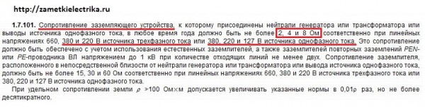
But the recommended value is indicated below under the icon **, which says that “The resistance of the grounding device, taking into account the repeated grounding of the neutral wire, should be no more than 2, 4 and 8 ohms, respectively, at line voltages of 660, 380 and 220 V of a three-phase current source or 380, 220 and 127 V of a single-phase current source.
You have an article about measuring grounding. However, it is not in the "Grounding" section.
It is located in the "Electrical Measurements" section.
Why do you take exactly 2, 4 or 8 ohm resistances. After all, these are the resistances of grounding devices connected to the neutral of a generator or transformer (suitable for measuring the resistance of a grounding device at a transformer substation). When measuring the resistance of a grounding device located around a (residential) building, it is more correct to take resistances of 15, 30 or 60 ohms. Correct me if I'm wrong.
Boris, you are right. In this article, I will soon make an addition-explanation of the resistance values of all types of grounding devices.
I agree with Boris, and we are waiting for clarifications ...
Good evening, I am operating cathodic protection stations. I have a question, what resistance (protective) should the memory of the cases of these installations have. I don’t understand either 10 or 4 ohms.
Pavel, I have not personally encountered the VHC, so my consultations on this issue may not be entirely complete. Open RD-91.020.00-KTN-149-06, in table 8.2. the norms of anode grounding are indicated depending on the resistivity of the soil and the length of the protected section of the oil pipeline in meters.
Good evening, I probably did not ask the right question. So, SKZ is a regular email. installation up to 1000V. As a rule, phase and zero are suitable for it, then a repeated (protective) ground is mounted nearby, connected to the SKZ case and to zero. I am interested in the protective grounding of this installation, and not the anode one (no more than 10 ohms). In the 1981 installer's book, I found that the resistance should be no more than 4 ohms. Although the current (industry) standard says 30 ohms. Something got confused. in the acceptance certificates at the SKZ, I saw 8-9 ohms, while it was indicated that it fits into the norm. I hope I managed to explain what I need to know.
Thanks.
PUE 1.7.61. Re-grounding of the GD of electrical installations that are powered by overhead lines must be carried out in accordance with PUE 1.7.102-1.7.103, i.e. for a voltage of 380/220, the resistance should be no more than 30 ohms. Also open PTEEP app. 3.1, tab. 36, all the same 30 ohms.
Good afternoon, wt. Dmitry! And what do you think, if the supports are on permafrost and, accordingly, all the grounding is there, then in winter this whole thing does not work?
Good evening! Please tell me, at one object, grounding was made according to technical specifications no more than 30 ohms. Measurements showed 11 ohms, everything is fine. Equipment arrived in the passport of which the power supply parameters are indicated and there is such an item "TOTAL TRANSITION RESISTANCE OF THE GROUNDING CIRCUIT DOES NOT EXCEED 0.5 Ohm". Does this mean that you need to continue to hit the stakes and achieve 0.5 ohms, or does it mean the resistance of the connections to the ground bus. Thanks a lot in advance!
Pavel, what kind of equipment and what voltage class? Most likely, the passport is talking about the transition resistance between the grounding loops of the ground loop and the PE bus (GZSH).
Equipment for photorejuvenation of the skin. Voltage 230 V, + - 10%. Thank you.
Pavel, in your case, it means checking the presence of a circuit between grounded installations (equipment case) and elements of a grounded installation (PE bus). According to PTEEP, clause 28.5, the contact resistance of the contacts should not exceed 0.05 (Ohm).
Hello, I am a beginner electrician, and your useful articles have helped me more than once))
And by the way, even in our local branch of Rostekhnadzor they showed presentations with your photos inserted into them with comments, I immediately recognized them and by the captions below the photo of the name of your site.
Thank you, now I'm preparing for the exam again according to your articles and passing the test)
Thanks, Pavel. It is very unexpected and pleasant to hear that Rostekhnadzor uses materials from the site in its presentations. I will not stop there, I will develop further.
Hi all! There is a simple folk way to check the quality of your grounding without any precision instruments. Take an ordinary incandescent bulb somewhere around 60 - 100 watts with an electric cartridge and connecting wires. The length of the wires is determined practically so that it is enough for you to connect to the "phase" in the house and to your ground. Connect one wire from the light bulb to the "phase" and the other to your ground. With a good ground, your light bulb will glow at full intensity. It will have a full voltage of 220 volts. If the light bulb glows badly at full heat, then your grounding is bad. It needs to be redone. Everything is very simple. Just follow the rules of electrical safety, do not touch bare wires with your bare hands. There is a dangerous voltage - 220 volts. All the best to you, success to you.
P.S. How to determine where the phase is in the outlet of your house - just insert the wire alternately into one hole in the outlet, and then into another. In which hole the light bulb will glow, there is a phase. Once again, all the best to you.
Hello Dmitry! Please tell me what should be the minimum cross-section of grounding conductors at a 10/04 kV substation for grounding the neutral of a transformer and switchgear up to and above 1 kV. Thank you very much in advance!
waiting for changes and additions
Can you please tell me what are the current norms for TKP 181?
point 2 of the table. 29.1 - I understand only for TP?
Where can I get the norm for lightning protection tp?
Re-grounding in TN system? (hostel, buildings)
Re-grounding in the TN system combined with lightning protection?
That's where about the rules. And it turns out I already unsubscribed here a year ago.
Well then. The norms are as follows: with a TN system and receiving power through the overhead line, the resistance of the GD of the ED should be no more than 30 Ohms for 380/220 V.
That is, the power plant is put into operation, it is not connected to the overhead line, we measure the memory, it should be no more than 30 ohms. Further. The power grids connect the branch to the overhead line, we re-measure - and here the resistance of the memory, taking into account the repeated groundings of the PEN conductor, should not exceed 4 ohms. If it exceeds - claims to the power grids.
It is necessary to measure 2 times, both during commissioning and in operation.
Thank you very much, point 4.3.2.13 tkp 181 is confusing, resist. re-grounding is not standardized? please tell me where it belongs. and where to get the norm for lightning protection of buildings (dormitories).
It says that when cable entry into the building, the re-grounding resistance is not standardized (with the exception of some cases of medical equipment, etc.). See the lightning protection resistance in tkp 336.
Sergey, according to the PUE, clause 1.7.61, it is RECOMMENDED to re-ground the PEN conductor, its resistance is not standardized. This is true for cable lines, since the next paragraph of the same paragraph says about the MANDATORY re-grounding of electrical installations that are powered by overhead lines.
This is easily explained: breaks in PEN conductors are frequent on the overhead line (a truck broke off, for example) and in the absence of a charger, voltage will appear on the non-current-carrying parts of the power plant. cable line if they do damage, then completely. Although CL is not immune from the lack of PEN contacts of the conductor.
Re-grounding during cable entry into the building is not standardized in clause 4.3.2.13 of TKP 339.
Re-grounding combined with lightning protection not more than 10 Ohm, clause 7.2.3 of TKP 336. If this is a TC, then see clause 4.3.8.2 of TKP 339, and the resistance of the lightning protection circuit should be specified in the project for this TC, if not, then TKP 336.
PUE 6th edition in the Republic of Belarus has been canceled in some parts, incl. clause 1.7, TKP 339 was introduced instead.
Boris, we are in the Russian Federation, the requirements of the TCH do not apply to us
Hello!
Can you specify what resistance value should re-grounding and lightning protection have?
It would not be bad if you wrote an article about re-grounding.
Hello.
the question is also interesting: what should be the resistance of the charger, provided that lightning protection is attached to it.
So far, I have only dug up that the lightning protection is either 100 Ohm, or when connected to the grounding of the house, the resistance should be the same as that of the house.
Hello.
The question is this: they threw me a branch on my pole where the shield with the counter is installed. Interestingly, the male or wire, as it is right, they threw the SIP only to the pole, and along the pole my aluminum monolith D ~ 4mm cable was already in the shield, connecting the SIP to my cable on the top of the pole with nuts. According to TU, grounding is prescribed. And how this grounding was done: A wooden pillar was dug into the ground along with a 120 channel, as it were, for reliability, and, of course, for grounding, to a depth of 1.5 meters. I installed the pole myself as they told me. I cut a 6mm thread in the channel and that's it. Good fellows arrived from the power grid, connected the cable in the shield, screwed the REN wire, as I understand it, to the shield itself and with a separate thick flexible wire from the same place to the channel with a screw, under which I threaded 6mm. That's all. They didn’t do anything and didn’t measure how you write about some Ohms.
Now I have a question ❓
Did they do everything right, And, in general, how should grounding be checked for Ohms and whether it can be done now that everything is connected and working.
Yegorych, the scheme is clumsy, but it contains the possibilities for transferring it from the TN-C system to the TN-C-S system.
1. It is necessary to replace the network section from the supply SIP to the introductory machine in the cabinet with 16mm2 AL or 10mm2 copper.
2. install a PE busbar (copper) connected to the housing in the cabinet
3. install bus N on insulators and make a jumper between PE and N
4 connect the PEN conductor from the supply line to the PE bus, as well as the wire from the channel.
The resistance of the grounding device can be measured with a special device. In accordance with paragraph 1.7.103 but d.b. at 220 v = 30 ohm
I don’t understand why put a zero bus on insulators if N and PE are the beginning of the PEN separation. - besides, it's good that the guys reinforce for reliability, connecting N and PE along the edges of the bus with two jumpers. And then, look, if there is only one jumper, and suddenly it unscrews ... ZERO disappeared and the kirdyk came to phase consumers. And God forbid, a negligent electrician took up Zero, and he has poor contact with PE - then a funeral march in general. Yes, these tires need to be welded. It is clear to separate them, what is needed in a common grounded "mecca" and why??? - yes, because a current flows through the working zero and it always has a potential relative to the ground. Therefore, it is impossible to zero with a working zero. To do this, there is a PE conductor taken from the “mecca” of a common, reliable grounding point. Now it is clear that PE serves as a good defense in all respects. 1. this is a reliable operation of the automata that is protected by current during a breakdown on the case (I'm not talking about a short circuit between zero). 2. good RCD sensitivity to parallel leakage current. And 3. it was not there, you are always in the zone of equalized potential, and there is no step voltage, and you will not be hit by current even if there is no RCD, but there is a well-developed system of UE and US.
************
What about my shield. I bought it in a specialized store, it is intended for installation on the street and it even had a certificate. The box is all iron, it has a nice, welded bolt for the PEN conductor and, and a good steel bar welded on with plenty of connections to separate the PE and N lines of your choice. All the zeros that are after the counter, I have supported RCDs on insulators on a DIN rail.
Yes, I almost forgot, my voltage is three-phase 380V 4-wire, And I take all the working zeros to the RCD from one bus where and PE.
And since the entire box is metal and well-tested, then it is considered to be re-grounded as a whole.
***********
Here's another nuance, I can't figure it out. The PEN wire enters the ASU and sits on the PE bus, and the PE bus (GZSH) is fixed directly to the ASU-0.4 (kV) case.
And then they say: - that the PEN wire and the PE bus need to be re-grounded. Do they live separately? Or if we talk about the PE bus, it is what you have, also on insulators from the ASU case, or the ASU lives on its own and is not welded to the charger
In any case, the memory is not a PEN conductor.
What do you have, according to your PUE, torn clumsily with the IEC, everything says: - where it is empty, and where it is dense.
victor: this input and the box on the pole, this is temporary, because it's all on a new plot for the construction of a cottage. My support stands on the site and after the construction of the house, according to the project, the input from the pillar :)) will be made into the house. Just then, I will do as you advised 10mm2 with a copper basin :) but for now, it will trample on.
In addition, I wrote about my AL cable that it has a diameter of approximately D ~ 4mm2
Well, of course, it is slightly larger in diameter, which is not difficult to calculate if you are friends with mathematics piD ^ 2/4 - this is 16mm2
Very convenient and cheap, I brought it into the introductory machine BA47-63A
The question is, how is it correct, in compliance with the PTB, to check the resistance of the ultrasound with the line already connected? or I'm saying something wrong or cunning :)
Egorych, start zero from the support on your steel bus in the shield (either copper or steel), it will also consider it a PE (GZSh) bus. Then you connect it to the channel, the resistance of which should be no more than 30 (Ohm) - see PUE, clause 1.7.103. This measurement must be done without connecting it to the PE bus. Thus, you have re-grounded, as required by this PUE. If you measure the total resistance, i.e. taking into account the repeated grounding of the overhead line + your channel, then it should be no more than 10 (Ohm), and preferably no more than 4 (Ohm). For measurements, invite an electrical laboratory.
Thus, the metal case of your shield is grounded, the PEN is re-grounded, which is what the PUE requires. More about separating the PEN conductor - there are several options for circuits. In addition, if later on in the built house you decide to organize a TT grounding system, then in principle you can not install the N bus, but take zero directly from the same PE bus.
Admin: - Tell me this situation.
My basement is buried in the ground to a depth of 1.6m. yes + even a strip foundation to a depth of 0.3 m. The width of the strip foundation under the wall blocks is 0.6 m, along the perimeter 12 * 13 meters + transverse walls. The entire strip foundation is reinforced with a three-dimensional frame with a longitudinal bare 0.2m and transverse 0.6m reinforcement D = 16mm fully welded in all joints and among themselves - now, I cursed :))
So, the question is: The shield will stand in the basement. Can I weld by opening the strip foundation to its frame, and this will be good grounding.
It is unlikely that there will be a normal grounding - concrete does not conduct well. Hammer a couple of pipes, corners, scald with a tire, it will be more reliable.
Yegorych, recalculate the wire cross-section D = 4mm according to your formula, if you don’t hurry, you will get somewhere 12mm2, but this is suitable for a makeshift.
Questions:
How and with what will you conduct electrical wiring?
How will you connect the channel with the shield's PE bus?
Do you all have such supports with channels on the plots?
For clarity, you need to invite a specialist to measure the resistance
grounding the channel and the foundation, without this it is impossible if you want everything to be fine.
Yegorych wrote - ... it is approximately D ~ 4mm in diameter ... And 16 mm.kv is obtained with a theoretical 4.5 mm, which rarely happens in practice. Do not scratch it hard - eye - not everyone has a diamond ...
victor: I didn’t measure the wire with a caliper, I didn’t think of it somehow :) I said by eye.
I will conduct electrical wiring: copper 2.5mm2 sockets, 1.5mm light, power to the kitchen 6mm2 and I don’t know how many phases - because I still don’t know about household appliances, but I know one thing -
1. cooking induction electric panel, possibly a box
2. instantaneous water heater 8kW, I don’t like storage devices, I’ve been using a flow for a long time and I don’t know how much hot water I need and don’t wait for it to heat up, and I don’t need cubes of water in tanks above my head for a family of 5 people.
> Do you all have such supports with channels on the plots? - Not. Who puts what. To whom the distance allows immediately to the house, most of the steel pipe, I had a 9 meter new wooden pole of the factory impregnation autoclave. I still tarred it, I think it will stand for a long time. I don't need a lightning tap on a steel pole.
At the moment, having read this site, I really liked it, without any show off and diplomas :)) of an academic degree, everything is as it should be for ordinary people.
> How will you connect the channel with the shield's PE bus? - I was puzzled, I don’t know yet, I don’t even know how to tie it up. Pull the PEN conductor back and forth or something)) from the pole to the channel back to the pole - then into the house - in short, I don’t know.
Maybe you are a victor: or someone who knows will tell you - it would not be bad, I will be grateful in advance.
SIP air with a twisted 4-wire cable (I think so) passes through reinforced concrete pillars 15 meters from the facade. The beginning of the line is 100 meters from the TP
At the expense of grounding devices, at least as far as I know, no one has done it here (maybe someone quietly himself :)
I think all the same to do as it is written on this site. there is no triangle, but a line of 5 meters yes.
I don’t understand one thing, why grounding conductors strike with a triangle or a line of 4-5 pins AND, which implies a resistance of the memory of 30 ohms. - which section - from where and to where. So I understand the resistor, you take and measure its resistance between the poles / terminals (two-pole element)
Yegorych, excuse me, I dragged in some electrical wiring, although I meant the power line from the pole to the house. First you need to determine where to split the PEN conductor.
If the support installed on the channel is not far from the house, as I understand it, 15m, and a bar is laid from the channel to the shield, an electric meter is also installed there, so I tend to separate the PEN conductor in this shield. To do this, I would replace the temporary cable from SIP-4 to the input box with a section of 16 in AL or 10 in copper. I installed a PE bus in it, connect the PEN and the grounding conductor from the re-grounding conductor to it, and installed the N bus. Next, I would lay a line to the shield in the house with a five-wire VBBSHV cable in the ground, it is possible in a steel pipe with another cable. I would make a ground electrode in a line of 5 three-meter electrodes with a distance of 3 meters between them. When performing power supply to VbbShv, its armor must be connected to the PE bus, which will significantly reduce the resistance of the grounding device. Also, in order to reduce R, I would connect the ground electrode to the metal reinforcement of the foundation concrete. I would do that, but there are other options
Good afternoon!
I'm reading! Helpful, interesting. Thank you!
Please explain how the resistance of the conductor is directly proportional to the voltage, and - inversely - to the current?
good evening! I would like to ask for advice! The site is located remotely, and it is not yet possible to measure the resistance of the grounding device, but the electrician who is located on the site indicates a high load of consumers and, as I understand it, the load on the grounding device is 20 A, it was also heated earlier ... Is such a thing acceptable? device, or is it time to take urgent measures to strengthen it?
It is completely incomprehensible - what does the grounding have to do with it? It should perform the functions of protection, and not serve as a current conductor.
in networks with a deadly grounded neutral, it is also a working zero. This is actually the problem.
Excuse me, but why is this here? One thing is a conductor with two functions, the other is the earth as a conductor. Don't catch the difference?
Good day, over the New Year holidays I re-read everything related to grounding, but did not find the answer to my question. There is a power plant with its own excellent grounding (by the way, surprisingly, all 0.4 kV connections at the facility are made according to the TN-S system). The power station outside the territory decided to build a construction trailer at a distance of 300 meters and connect it to a single-phase network. The ground loop at the station turned out to be so good that a steel strip with a cross section of 250 mm2 was laid next to the trailer, connected to a common ground loop. There is a huge temptation not to pull N, PE and L from the power assembly, but to limit ourselves to only two wires, by the way, the division into PE and N conductors is made immediately in the auxiliary transformer compartment, then an introductory power switch is installed that feeds the assembly, and then more are fed from this assembly assemblies. Taking into account the choice of a 20A machine with characteristic B (a cable with a cross section of 6mm2 in terms of phase resistance - zero passes end-to-end) in terms of resistance loop phase - PE, I think everything will be fine too). 1. Will there be a mistake if I use instead of a PE conductor coming from the transformer a steel strip of the ground loop. 2 Would it not be a mistake not to make a trailer ground loop.
Hello site owner. Please let me know if there are any articles on the site about protective conductors from electrical installations for GZSH or ground loops? By the nature of my work, I am faced with the installation of explosion-proof manual fire detectors in hazardous areas. They must be grounded using special grounding conductors. And this manual PI stands near the tank in the field. The nearest point of possible grounding can be 100-200 meters. Do not make a grounding device nearby. Is it possible to throw a protective conductor at 100-200 meters? What resistance should this conductor have?
Registration: 09.02.09 Messages: 149 Acknowledgments: 4
Registration: 17.07.10 Messages: 884 Acknowledgments: 301
Also, the resistance of the circuit to pulsed currents is less than to currents with a frequency of 50 Hz, while for a deep modular memory it is the other way around!
You also need to know that the protective grounding of the house and the equalization, potential equalization systems in the house when using TN systems, one of which is the TN-C-S system, do not protect outdoors when using electrical appliances protection class 1, these are those with protective contacts on the plug or ground terminal on the case, in case of a power failure.
GOST R 50571.3-94 413.1.3.9 said:
When a residual current protective device is used to automatically disconnect a circuit outside the coverage of the main potential equalization system, exposed conductive parts should not be connected to the TN system network, but the protective conductors should be connected to an earthing conductor having a resistance to ensure operation of this device. A circuit protected in this way may be considered a TT system network (see 413.1.4).
Note - Outside the coverage of the main potential equalization system, other protective measures can be used:
- power supply through a separating transformer;
- application of additional insulation (see 413.2)
The maximum consumption will be up to 10 kW. What section to pull the wire from the metal plate, which will be on the foundation, to the shield?
Power has nothing to do with it at all. The cross section must be at least 10 mm2 for copper or 16 mm2 for aluminum.
Why dig so much, not to mention the fact that unnecessary soil will be loosened, which will affect the memory resistance for the worse. Everything is done much easier.
Instead of the notorious triangle driven into the heads of inexperienced, it is better to drive the same pins with the same distance in a straight line along the wall of the house, at least the resistance of such a memory will be less due to the better pin utilization. Also, such a design will be part of the ground loop of the house, which will provide at least a primitive equalization, alignment of the conductive parts of the house. In the future, in parts or all at once, it will be possible to make a full-fledged grounding loop at home.
Places of welding and exit to the surface from a depth of 30 centimeters to a height above the surface of 30 centimeters should be well cleaned and treated with an anti-corrosion coating. The backfilled soil should be homogeneous, without stones and debris. At least the first backfilled soil up to 20 centimeters above the grounding device must be tamped.
It is called a device for measuring ground resistance, there are many different models, it is expensive to buy for a one-time use.
It is easier to drive in a corner that the grinder needs to make sharp. The pipe is flattened on one side, so that it is easier to drive in; before flattening, it is also better to cut it obliquely with a grinder.
Registration: 23.05.10 Messages: 10.446 Acknowledgments: 3.313
Registration: 20.07.07 Messages: 1.377 Acknowledgments: 366