Star news


Electronic voltmeters of alternating voltage. Analog electronic voltmeters
REPUBLIC OF KAZAKHSTAN
AVIEK University
FACULTY OF COMPUTER SCIENCE
DISCIPLINE: “Standardization and measurement technologies”
TEST: “ANALOG ELECTRONIC VOLTMETERS.”
Completed:
St. gr. ZPOS-96-1
Grinev M.V.
Associate Professor, Ph.D.
Nurmanov M.Sh.
Almaty 2000
VOLTAGE MEASUREMENT WITH ELECTRONIC ANALOG VOLTMETERS
Electronic analog voltmeters are the first example of electronic measuring instruments covered in the course. Among them there are both direct conversion voltmeters and comparison voltmeters. Let's consider the operating principle, block diagrams and main functional units of analog voltmeters for direct conversion and comparison.
The adjacent table shows the relationship between actual values and average values as a function of waveform. Therefore, for voltmeters whose scale is calibrated for a given waveform, the indication is correct only for that waveform, in other cases the indication is less.
Observations on the operation of a voltmeter with detection. Signal dependence. The voltmeter whose reading is least affected by the presence of harmonics is the actual value because it is sensitive to the heat generated by each component of the actual value.
ANALOG DIRECT CONVERSION VOLTMETERS
The block diagram of an electronic analogue direct conversion voltmeter corresponds to the typical diagram in Fig. 2.1 and, as can be seen from Fig. 3.13, in the most general case, includes an input device (ID), the input of which is supplied with the measured voltage Ux, IP and magnetoelectric device used as a control unit.
In addition, voltmeters using square-law detection are not affected by the presence of harmonics; they measure the effective value of the signal regardless of its shape. The frequency range is determined by the frequency band of the voltmeter. This is usually wideband, so actual and average voltmeters have a range between Hz and 10 MHz. In this case, if the voltmeter input connections are inverted, the readings will be different. Response time is the interval between the application of a signal and the setting of the indication.
It is on the order of 0.5 s with average voltmeters and reaches 2 s with effective voltmeters due to thermal inertia. It is internal and external. Internal noise is proportional to the voltmeter bandwidth and is independent of the detection type used. A high voltmeter produces significant errors because the noise signal is unpredictable. Sampling may be coherent or incoherent. In the first case, samples are taken at regular intervals. It is used when the waveform needs to be preserved.
Input device In the simplest case, it is a divider of the measured voltage - an attenuator, with the help of which the measurement limits of the voltmeter are expanded. In addition to exact division Ux, The AC should not reduce the input impedance of the voltmeter, which, as has been repeatedly emphasized, affects the methodological measurement error Ux- Thus, the use of a VU in the form of an attenuator is, in addition to additional
When it is desired to measure only the signal size, non-matched sampling is preferred. Samples are taken at irregular time intervals, without connection to any of the component frequencies of the signal. There are devices that display the measurement result directly in numerical form. They are designed to measure continuous voltages. Numerical multimeters are multifunctional options that can additionally measure alternating voltages, continuous and alternating resistive currents.
A simplified block diagram of a numerical voltmeter is shown in Fig. The most commonly used ones with advantages are advantages with comparison and double integration. To evaluate the accuracy of the conversion, it should be taken into account that the measured voltage is sampled into several elementary stages, easily numbered. The stage must correspond to a well-defined value. This is the smallest zero value specified by the device. In addition, the two adjacent directions differ from each other at this elementary stage.
Rice. 3.13. Generalized block diagram of a direct conversion analog voltmeter.
resistances and measuring voltage transformers, another way to expand the measurement limits of voltmeters. It is this method that is used in electronic voltmeters and other radio measuring instruments.
As an IP in voltmeters direct current(B2) a direct current amplifier (DCA) is used, and in alternating and pulsed current voltmeters (VZ and B4) a detector is used in combination with a DCCA or amplifier alternating current. Converters in other types of voltmeters have a more complex structure. In particular, selective voltmeter converters (B6) must provide, in addition to signal detection and amplification, its frequency selection, and phase-sensitive voltmeter converters (B5) must provide the ability to measure not only the amplitude, but also the phase parameters of the signal under study.
This is what is called the resolution of a numerical voltmeter. Resolution is a design parameter, not a single measurement result. The illustration is a block diagram of a numerical voltmeter with a comparison with successive approximations - Fig. It is characterized by high accuracy, being one of the most common types.
The input of the comparator is supplied with a voltage to measure the alternating reference voltage, which is obtained as the output voltage of the digital-to-analog converter. The command is controlled by a logic control unit, which takes the readings of the comparator and seeks to equalize the two voltages from the comparator input.
The block diagram of an analog DC voltmeter corresponds to the generalized diagram in Fig. 3.13. The main functional unit of such voltmeters is the UPT. Modern DC voltmeters are designed primarily as digital instruments.
Depending on the purpose, AC and pulse current voltmeters can be designed according to one of two block diagrams (Fig. 3.14), differing in the type of power supply. In voltmeters of the first modification (Fig. 3.14, A) measured voltage Ux^ converted to constant pressure Ux=, which is then measured by a DC voltmeter. On the contrary, in voltmeters of the second modification (Fig. 3.14, b) The measured voltage is first amplified by an AC amplifier and then detected and measured. If necessary, a UPT can be additionally connected between the detector and the DUT.
Characteristics of numerical voltmeters. Accuracy - cannot be characterized by a single class index, similar to analog voltmeters. Some errors are independent of the measured value, while others are dependent on it. A global index of error characteristics is introduced.
It determines the quantification error. The sensitivity of a voltmeter at a certain scale is equal to half the resolution value and represents the limit of uncertainty on the true value of the measured quantity, and the device is insensitive to variations within this limit.
Comparing the block diagrams of Fig. 3.14, even before considering the circuit solutions of their functional units, it is possible to draw certain conclusions regarding the properties of voltmeters of both modifications. In particular, voltmeters of the first modification do not have the same restrictions regarding the frequency range of measured voltages as voltmeters of the second modification, where this parameter depends on the bandwidth of the AC amplifier. But voltmeters of the second modification have high sensitivity. From the course “Amplification Devices” it is known that using an AC amplifier you can obtain a significantly higher gain than using a UPT, i.e., design microvoltmeters with a lower limit Ux^. limited by the amplifier's own noise. Due to change
Measurement speed is the relationship between the number of numeric orders displayed and the measurement or decision time. These noises are spurious signals that appear in series with the measured signal. They usually originate from a network hub, but they can also be of varying nature with some frequency.
Their purpose is to facilitate the operation of the device and provide increased measurement accuracy. The most common intuitions. Device for automatic domain switching. Circuits for automatic correction of gap stress and creep. The actual converter's response is offset from the ideal exactly with the offset voltage. A similar shift also occurs when the error characteristic of the input voltage changes. In principle, there are two possibilities for correcting the gap voltage. - by compensating the offset voltage using circuits with appropriate temperature behavior; - introduction into the operating cycle of the voltmeter of phases of checking and automatic correction of errors caused by voltage offset.
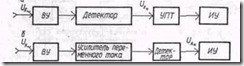
Rice. 3.14. Block diagrams of analog voltmeters for alternating and pulsed current:
a-with a detector at the entrance; b - with an AC amplifier at the input.
the division factor of the power supply and the gain of the amplifiers, the range of measured voltages can be large for voltmeters of both modifications.
The first procedure has the disadvantage that, due to the derivation, compensation is temperature dependent and can be performed ideally for one, or at most two, temperatures using complex circuits. This is why the second method is used almost exclusively. During the measurement steps, the accumulated voltage will be reduced from the useful signal, the result is correct. A value other than 1 total centimeter of the converter causes multiplicative errors.
The gain or overall gain of the converter is determined by the semi-deflection slope that connects the transfer points corresponding to the nominal voltages. The elementary pitch is determined by the difference between these two voltages.
Detector type in block diagrams Fig. 3.14 determines whether voltmeters of both modifications belong to amplitude, root-mean-square or medium-rectified voltage voltmeters. In this case, pulse current voltmeters (B4) are designed only as voltmeters of the first modification in order to avoid distortion of the pulse shape in the alternating current amplifier. When measuring the voltage of single and rarely repeating pulses, either diode-capacitive pulse expanders in combination with detectors or amplitude-time pulse conversion, characteristic of digital voltmeters, are used.
Correction can be done either from the digital or analog side. In the first option, each measurement is performed in two stages. Being instruments with high precision and sensitivity, it is necessary to eliminate the influence of interference on measurements. The main source of alarm voltages is the power supply. There are two ways to reduce these errors: - protection signal circuits; - use of isolation transformers. The connection of the voltmeter to the measuring circuit plays an extremely important role, allowing errors thus causing significant errors.
Let us now consider a typical block diagram of selective voltmeters, which are used in measuring small harmonic voltages under interference conditions, in studying the spectra of periodic signals, and in a number of other cases. As can be seen from Fig. 3.15, the voltmeter is essentially a superheterodyne receiver, the principle of operation of which is explained in the course “Radio Engineering Circuits and Signals”.
In addition to the beneficial effect, the presence of a shield increases the mass capacitance of shielded circuits. In this situation, due to the high impedance of the device circuits relative to the cassette, the presence of a disruptive electric field from the network will cause destructive common mode voltage.
Limiting the effect of these disturbances is possible through shielding. The correct way to implement a numerical voltmeter screen is shown in Fig. It is observed that only analog circuits are shielded, while numerical circuits have a higher immunity to interference. To protect the operator, the cassette is connected to memory. The test lead shield is also connected to the cassette. In this situation, this reduction is all the more important because the device circuit capacity is lower. Therefore, in performance devices, the analog circuits are galvanically separated from the numerical circuits, the latter having a ground connected to the cassette.
Frequency selection of the input signal is carried out using a tunable local oscillator, a mixer (CM) and a narrow-band intermediate frequency amplifier (IFA), which provides high sensitivity and the required selectivity. If selectivity is insufficient, double and sometimes triple frequency conversion can be applied. In addition, selective voltmeters must have an automatic frequency control system and a calibrator. Calibrator - exemplary
Thus, the effect of the containers relative to the box is canceled. The separation is carried out using. Optical connectors. Through which signals are transmitted from analog to numerical circuits and vice versa. Galvanic separation. Separation of the mass of analog circuits from the mass of digital circuits.
Avoiding the sum of the wanted signal with the voltage drop caused by numerical circuit currents on the analog conductor conductor impedance. The disturbances introduced in this way are important, especially when the numerical part is implemented with logic circuits that generate rapid changes in current through mass conductors.
source (generator) AC voltage a certain level, which makes it possible to exclude systematic errors due to changes in the local oscillator voltage when it is adjusted, changes in the transfer coefficients of the voltmeter components, the influence of external factors, etc. The voltmeter is calibrated before measurement when switch P is set from position 1 to position 2.
Other ways to improve common mode failure. Double shielding of the connecting conductor, which is a continuation of the floating shield method at the level of the connecting conductor. Connection diagrams vary depending on the characteristics of the circuit whose voltage is determined. Mass-isolated source. The T transmitter, although completely isolated from the table, accepts the output terminal's connection to ground. In this case, the device is also protected. A circuit whose terminals must be isolated from the table.
This shield eliminates common-mode voltage generated by the grid's electric field and provided by the high impedance of the circuit board. The use of resistors is related as shown in Fig. Their values are selected as follows: - the voltage drops across the resistors are the same, which corresponds to the maximum currents in different measurement ranges; - the value of these voltage drops should be lower.
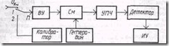
Rice. 3.15. Block diagram of a selective voltmeter.
In conclusion, we note that in one device it is not difficult to combine the functions of measuring direct and alternating voltages, and with the help of additional functional units and corresponding switchings (by analogy with rectifier devices) to form combined devices called universal voltmeters (B7). Modern types of such voltmeters, as a rule, are designed as digital devices, which makes it possible to further expand their functionality and increase accuracy. In this regard, the features of constructing block diagrams of universal voltmeters will be considered in the works of colleagues.
The first condition ensures the measurement of currents using one measuring range of the voltmeter, which simplifies the design of the device, and there is no need to simultaneously switch the ranges of the voltmeter with resistors. The second condition is necessary so as not to change too much high current in the circuit under study, being specific to any device. To convert relatively low frequencies to alternative voltages, the following are used: - precision detectors for the rectified average value; - Effective value converters.
ANALOG VOLTMETERS COMPARISON
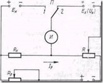
Rice. 3.16. Measuring potentiometer circuit.
Electronic analog comparison voltmeters for the most part implement the most common modification of the comparison method - the zero method. Therefore, they are more often called compensatory voltmeters. Compared to direct conversion voltmeters, these are more complex, but also, as previously emphasized, more accurate instruments. In addition, from the diagram in Fig. 2.2 it is clear that at the moment of compensation DХ = 0 and the device does not consume power from the source X. In relation to compensation voltmeters, this means the ability to measure not only voltage, but also the EMF of low-power sources. In the practice of electrical and radio measurements, such measurements are carried out using both electronic compensation voltmeters and electromechanical ones. To explain the use of the zero method when measuring EMF and voltage, let us first consider the classical circuit of an electromechanical DC compensator, shown in Fig. 3.16.
By multiplying this voltage we obtain a size equal to the effective value of the measured signal that is displayed. The multimeter reading is only valid in sinusoidal mode, which is the main limitation of this conversion. The main advantage is high accuracy. The actual value converter has a wide spread due to its ability to be used in non-sinusoidal mode, its simplicity and integrated implementation. Under these conditions, the value of the continuous voltage will be equal to the effective value of the input signal.
One of the main functional units of any compensator is a high-precision variable resistor R, on the scale of which the measured EMF value is measured (Ex) or voltage (Ux). Therefore, compensators are usually called measuring compensators according to GOST 9245-79 potentiometers. EMF is used as an exemplary measure normal element(NE) - electrochemical source, EMF (Ea) which is known with a very high degree of accuracy. However, the capacity of the NE is small, and long-term comparison during the measurement process Ex(Ux) With Yong impossible. Therefore, the potentiometer circuit is supplemented with an auxiliary source of EMF (Eo) of large capacity. For comparison with Ex(Ux) the voltage drop across the reference resistor is used Rn., generated by current from the source EO- operating current (Iр), which is pre-set. Therefore, the measurement process Ex{ Ux) should consist of two stages.
Among the most important parameters of the circuit: - frequency range covered. The system is a control loop that sets the voltage supplied by the generator to a value for which the amplitudes of the signals at the inputs of the two detectors are practically equal. This is explained by the identical characteristics of the detector, which emphasizes the equality of amplitudes; - high measurement accuracy, mainly determined by precision detection errors, which are small.
Resistance is a voltage conversion. For large resistances the drop will be too high or require very low DC currents. Large resistors - fig. 32: inverter output voltage. What sample can be used? The main advantages of numerical voltmeters are listed.
At the first stage, the required value of Ip is established. To do this, set the switch to position 1 and use the potentiometer Rp achieve a zero reading of the I indicator (usually a magnetoelectric galvanometer). As can be seen from Fig. 3.16, this corresponds to IpRn=En, i.e. the operating current Iр, which must then remain constant, will reproduce the value during the measurement process En.
At the second stage, the Ex(Ux) value is measured. To do this, the switch is moved to position 2, and changing the resistance of the potentiometer R again achieve a zero reading of I. When Iр = const this corresponds to Ex (Ux) = IpR, i.e. the desired value Ex(U^}^. R and can be counted on a scale R.
Thus, the metrological characteristics of DC measuring potentiometers are determined by the parameters of the NE, standard resistors, indicator and source Ey. Saturated and unsaturated reversible galvanic cells are used as NEs, the positive electrode of which is formed by mercury, and the negative electrode by cadmium amalgam. NE accuracy classes are regulated by GOST 1954-82 within the range of 0.0002...0.02 and determine the accuracy class of the potentiometer as a whole. Potentiometer R is performed according to a special scheme that ensures the constancy of /p when changing R and the required number of signs (decades) when counting Ex(Ux). These requirements are met by circuits with replacement and shunt decades.
Measuring potentiometers can also be used to measure alternating voltages. However, in this case the compensating voltage must be adjusted not only in magnitude, but also in phase. Therefore, such potentiometers have a more complex circuit than DC potentiometers, and are significantly inferior in accuracy to them due to the lack of a standard measure for alternating current, similar in its characteristics to the NE. In the practice of electrical and radio measurements, they are completely replaced by electronic compensation voltmeters.
In compensation voltmeters, the measured voltage (DC, AC, pulse) is compared with the DC compensation voltage, which in turn is accurately measured by a DC voltmeter and is a measure Ux. A typical block diagram of such a voltmeter is shown in Fig. 3.17.
As can be seen from Fig. 3.17, the basis of the voltmeter is a compensation IP, consisting of a measuring diode V s load R, regulated source constant compensating voltage -Ek, amplifier and indicator with two stable states. With absence Ux indicator implemented using
functional nodes are in the first stable state, and at a certain threshold value they go into the second state. Measurement process Ux just comes down to a gradual increase Ek until the indicator reaches the second stable state. Meaning Ek, corresponding to the moment of transition, is measured by a DC voltmeter and is a measure Ux.
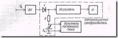
Rice. 3.17. Block diagram of a compensation voltmeter.
In combination with other circuit solutions (use of an indicator with a low threshold voltage, a tube measuring diode with a stable characteristic, etc.), it becomes possible to design high-precision compensation voltmeters.
The disadvantage of the considered scheme is the need to install To her manually. Therefore, in most voltmeters the power supply circuit is complicated, providing automatic compensation Ux And Ek. Autocompensation voltmeters are direct-indicating devices and are more convenient to use.
MAIN UNITS OF ANALOG VOLTMETERS
Let's consider the circuit designs of the main functional units that determine the metrological characteristics of analog voltmeters. Most of these components are also used in other types of electronic measuring instruments.
Input device
As mentioned above, the VU is intended to expand the measurement limits of the voltmeter. In the simplest case, it is an attenuator made using resistive (Fig. 3.18, a), capacitive (Fig. 3.18, b) or combined (Fig. 3.18, c) circuits.
Fulfilling the remaining requirements and, above all, ensuring a high input resistance and minimal input capacitance of the voltmeter leads in some cases to a more complex structure of the voltmeter. The most universal and often used in modern AC voltmeters is the VU, the block diagram of which is shown in Fig. 3.19.
The fundamental feature of this circuit is the change in Uv using a low-resistance resistive attenuator with constant input and output impedance. This improves measurement accuracy Ux~, but it requires the introduction of an impedance converter (CI) into the structure of the control unit, which ensures the transformation of the high input resistance of the voltmeter into the low input resistance of the attenuator. A voltage follower based on a field-effect transistor with deep negative feedback is most often used as a PI. By using
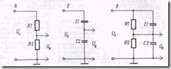
Rice. 3.18. Voltmeter attenuator circuits:
a-on resistors; b - on capacitors; c - combined.
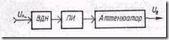
Rice. 3.19. Block diagram of a universal input device.
The input voltage divider (VDN) provides an additional possibility of expanding the measurement limits of the voltmeter. VDN is a fixed resistive-capacitive type divider (see Fig. 3.18, V)
At high frequencies, the input resistance of the voltmeter decreases, and the input capacitance and inductance of the conductors form a series oscillating circuit, which at the resonant frequency has practically zero resistance. To neutralize these effects, the PI is structurally performed as an external sampler with VDN in the form of a nozzle.
Amplifiers
DC amplifiers, as can be seen from the block diagrams (see Fig. 3.13 and 3.14, o), provide sufficient power to drive the IM magnetoelectric device and match the input resistance of the IU with the output resistance of the device or detector. There are two main requirements for the UPT: high constancy of the gain and negligible fluctuations of the output value in the absence of Ux= (Zero drift). Therefore, all practical UPT circuits have deep negative feedback (NFE), ensuring their stable operation and insensitivity to overloads. Radical methods of combating zero drift are its periodic correction, as well as transformation Uх= into alternating voltage with subsequent amplification and rectification of this voltage.
AC amplifiers, in accordance with their functional purpose (see Fig. 3.14, b), must have high sensitivity, great importance and high stability of the gain, low nonlinear distortion and wide bandwidth (with the exception of the selective voltmeter amplifier). Only multistage amplifiers with feedback loops and elements for correcting the frequency response can satisfy these contradictory requirements. In some cases, logarithmic amplifiers are used to obtain a linear scale in decibels. If the task is to minimize the additive error of the voltmeter, the amplifiers can be two-channel with amplification of the main signal and the signal that corrects the additive error. To expand functionality, many voltmeters have a special amplifier output and can be used as broadband amplifiers. Moreover, amplifiers can be produced as independent measuring instruments, forming the U subgroup.
DC and AC amplifiers are discussed in detail in the course “Amplification Devices”.
Detector
The type of detector determines, as already indicated, whether alternating current voltmeters belong to amplitude, root mean square, or average rectified voltage voltmeters. In accordance with this, the detectors themselves are classified as follows: by parameter Ux~^ to which the current or voltage in the output circuit of the detector corresponds: peak detector, detectors of rms and rms voltage values; according to the input circuit: detectors with open and closed DC voltage input;
according to detection characteristics: linear and quadratic detectors.
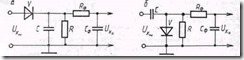
Rice. 3.20. Peak detector circuits:
A - with open entrance; B - s closed entrance.
Peak detector - This is a detector whose output voltage directly corresponds to t/max or<7min (Ov or Us). The peak detector is linear and can have an open (Fig. 3.20, a) or closed (Fig. 3.20, b) DC voltage input.
The operating principle of peak detectors is specific and consists in charging the capacitor C through a diode V to the maximum (peak) value Ux~ , which is then remembered if the discharge time constant C (via R) significantly exceeds the charging time constant. Switching polarity V determines the correspondence Ux=, or Umax(UV), or Umin(Un), and possible pulsations U x= smoothed with a chain Russia, Sf. If the detector has an open input, U x= is determined by the sum of U and UV(Un), i.e. corresponds to Umax (Umin) With input U closed x= corresponds UV(Un). If Ux~ does not contain a constant component, then the circuits shown in Fig. 3.20, a, b, are identical, and U x= corresponds Um. In some cases, full-wave peak detectors with voltage doubling are used to directly measure the voltage peak-to-peak value.
A significant advantage of peak detectors is their large input impedance (equal to R/2 for the diagram in Fig. 3.20, A And R/3- for the diagram in Fig. 3.20, b) and the best frequency properties compared to other types of detectors. Therefore, peak detectors are most often used in voltmeters of the first modification (see Fig. 3.14, o), structurally designed together with a remote control unit in the form of an external probe. In this case, the cable connecting the probe to the device transmits Uх=.
RMS detector - It is an AC to DC current (voltage) converter proportional to U 2 sk. The detection characteristic in this case should be quadratic, and at If U- is present, a detector with an open input is required. Modern types of voltmeters mainly use quadratic detectors with thermal converters similar to thermoelectric ammeter converters. Their main disadvantage, as noted earlier, is the quadratic nature of the instrument scale. In voltmeters, this drawback is eliminated by using a differential circuit for connecting two (or more) thermal converters, as shown in Fig. 3.21.
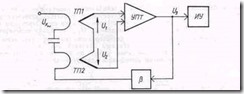
Rice. 3.21. Block diagram of an rms voltage detector.
When the measured voltage is applied to the thermal converter TP1 Ux~ output voltage TP1 by analogy with (3.26) U 1 =k t U 2 sk.
In addition to TP1, the circuit has a second thermal converter TP2, connected opposite to TP1. Feedback voltage is applied to TP2, so it
output voltage U 2 == k t BU 2 3 .
Thus, at the input of the UPT there is a resulting voltage
U 1 – U 2 = kt(U 2 sk - BU 2 3)
what does it correspond to
U 3 = k upt k t (U 2 sk - BU 2 3).
If the circuit parameters are chosen so that
k upt k t BU 2 3 >> U 3 ,
then finally U 3 º Usk, i.e., the IU scale will be uniform.
Average rectified value detector - This is an alternating voltage to direct current converter proportional to Ust. Circuit-wise, it is based on a full-wave semiconductor rectifier, considered in the analysis of rectifier ammeters (see § 3.4.1). It must be added, however, that the linearity of the characteristics of such detectors will be better, the more Ux~(at small Ux~ the detector becomes quadratic). Therefore, average-rectified detectors are, as a rule, used in voltmeters of the second modification (Fig. 3.14, b).
Such voltmeters consist of an AC-to-DC voltage converter, an amplifier and a magnetoelectric measuring mechanism. There are two possible generalized block diagrams of alternating current voltmeters (Fig. 4.17), differing in their characteristics. In voltmeters according to the diagram in Fig. 4.17, A measured voltage their is first converted to DC voltage, which is then applied to UPT And THEM, which are essentially a DC voltmeter. Converter Etc is a low-inertia nonlinear link, so voltmeters with this structure can operate in a wide frequency range (from tens of hertz to 10 3 MHz).
Fig.4.17. Block diagrams of AC voltmeters
In voltmeters made according to the circuit in Fig. 4.17, b, thanks to preliminary amplification, it is possible to increase sensitivity. However, creating high-gain AC amplifiers operating over a wide frequency range is a rather difficult technical task. Therefore, such voltmeters have a relatively low frequency range (1 - 10 MHz); the upper measurement limit at maximum sensitivity is tens or hundreds of microvolts.
Depending on the type of AC to DC voltage converter, the deviations of the pointer of the measuring mechanism of voltmeters can be proportional amplitude(to peak), average(medium straightened) or current measured voltage values.
Peak value voltmeters have amplitude value converters (peak detectors) with open (Fig. 4.18, A) or closed (Fig. 4.19, A) entrances where and input And and out- input and output voltage of the converter.
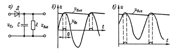
Rice. 4.18. Diagram (a) and timing diagrams of signals (b and c) of the amplitude value converter (peak detector)
with open entrance
In amplitude converters with an open input, the capacitor is charged almost to the maximum their m ah positive (for a given diode switching on) value of the input voltage (see Fig. 4.18, b). Voltage ripples uout on the capacitor are explained by its recharging when the diode is open and discharge through resistor R when the diode is closed.
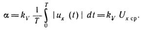
Average output voltage and cf" and htah and, therefore, the angle of deflection of the measuring mechanism pointer
![]() (4.29)
(4.29)
Where k y- voltmeter conversion coefficient.
A feature of amplitude converters with an open input is that they pass the DC component of the input signal (positive for the shown inclusion of the diode)
At and in = U o + U m sin ωt average output voltage and CP ≈ U o + Um. Hence,
![]() (4.30)
(4.30)
Obviously, for U BX<0 подвижная часть THEM will not deviate, since in this case the diode is closed D.
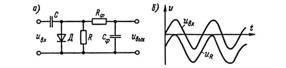
Rice. 4.19. Circuit (a) and signal timing diagrams (b)
amplitude converter with closed input
In converters with a closed input (Fig. 4.19, a, b) in steady state on a resistor R Regardless of the presence of a constant component of the input signal, there is a pulsating voltage u R varying from 0 to -2 Um Where Um- amplitude of the alternating component of the input voltage. The average value of this voltage is almost equal to Um. To reduce output voltage ripple, a low-pass filter R f C f is installed in such converters. Thus, the voltmeter readings in this case are determined only by the amplitude value of the alternating component of the input voltage their, i.e. a = k v U m .
Since the voltmeter scale is calibrated in effective values of sinusoidal voltage, when measuring voltages of other forms it is necessary to make an appropriate recalculation if the amplitude coefficient of the measured voltage is known. Amplitude value of the measured voltage of non-sinusoidal shape
Where k ac == 1.41 - amplitude factor of the sinusoid; U np- voltage value measured on the instrument scale.
RMS value of measured voltage
Where k a- amplitude coefficient of the measured voltage.
Average value voltmeters have AC-DC voltage converters, similar to the converters used in rectifier devices. Such voltmeters usually have the structure shown in Fig. 4.17, b. In this case, a pre-amplified voltage is supplied to the rectifier converter their, which increases the sensitivity of voltmeters and reduces the influence of diode nonlinearity. The angle of deflection of the moving part of the measuring mechanism in such voltmeters is proportional to the average rectified value of the measured voltage, i.e.
 (4.33)
The scale of such voltmeters is also calibrated in effective values of sinusoidal voltage. When measuring a non-sinusoidal voltage, the average value of this voltage
and the current one:
Where U PR- voltmeter reading; k fs= 1.11 - sinusoid shape factor; k F- shape factor of the measured voltage.
RMS voltmeters have an AC voltage converter with a quadratic static conversion characteristic and OUT = k u IN 2 . Thermal converters, squaring devices with piecewise linear approximation of a parabola, vacuum tubes, and others are used as such a converter. Moreover, if the rms value voltmeter is made according to the block diagrams shown in Fig. 4.17, then, regardless of the shape of the measured voltage curve, the deviation of the measuring mechanism pointer is proportional to the square of the rms value of the measured voltage:
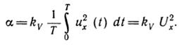 (4.36)

