Star News


Homemade unch on transistors. How an audio amplifier works
A low frequency amplifier (ULF) is such a device for amplifying electrical oscillations corresponding to the frequency range audible to the human ear, i.e. ULF should amplify in the frequency range from 20 Hz to 20 kHz, but some ULF can have a range up to 200 kHz. ULF can be assembled as an independent device, or used in more complex devices - TVs, radios, radios, etc.
The peculiarity of this circuit is that the 11th output of the TDA1552 microcircuit controls the operating modes - Normal or MUTE.
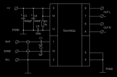
C1, C2 - bypass blocking capacitors, used to cut off the constant component of the sinusoidal signal. Electrolytic capacitors should not be used. It is desirable to place the TDA1552 chip on a heatsink using heat-conducting paste.
In principle, the presented circuits are bridge circuits, since there are 4 amplification channels in one TDA1558Q microassembly case, therefore pins 1 - 2, and 16 - 17 are connected in pairs, and they receive input signals from both channels through capacitors C1 and C2. But if you need an amplifier for four speakers, then you can use the circuit option below, although the power will be 2 times less per channel.
The basis of the design is the TDA1560Q class H microassembly. The maximum power of such an ULF reaches 40 W, with a load of 8 ohms. Such power is provided by an approximately doubled voltage due to the operation of the capacitors.

The output power of the amplifier in the first circuit assembled on the TDA2030 is 60W at a load of 4 ohms and 80W at a load of 2 ohms; TDA2030A 80W at 4 ohm load and 120W at 2 ohm load. The second circuit of the considered ULF is already with an output power of 14 watts.

This is a typical two-channel ULF. With a little piping of passive radio components on this chip, you can assemble an excellent stereo amplifier with an output power of 1 watt per channel.
Microassembly TDA7265 - is a fairly powerful two-channel Hi-Fi class AB amplifier in a typical Multiwatt package, the microcircuit has found its niche in high-quality stereo technology, Hi-Fi class. Simple switching circuits and excellent parameters made the TDA7265 a perfectly balanced and excellent solution for building high-quality amateur radio equipment.
The Micro Assembly is a class AB quad amplifier designed specifically for use in automotive audio applications. Based on this microcircuit, several high-quality ULF variants can be built using a minimum of radio components. The microcircuit can be advised to beginner radio amateurs for home assembly of various acoustic systems.
The main advantage of the amplifier circuit on this microassembly is the presence of four independent channels in it. This power amplifier works in AB mode. It can be used to amplify various stereo signals. If desired, you can connect to the speaker system of a car or a personal computer.
TDA8560Q is just a more powerful analogue of the TDA1557Q chip, widely known to radio amateurs. The developers only strengthened the output stage, thanks to which the ULF is perfect for a two-ohm load.
The LM386 micro-assembly is a ready-made power amplifier that can be used in low-voltage designs. For example, when the circuit is powered by a battery. LM386 has a voltage gain of about 20. But by connecting external resistances and capacitances, you can adjust the gain up to 200, and the output voltage automatically becomes equal to half the supply voltage.
The LM3886 micro-assembly is a high quality amplifier with an output of 68 watts into 4 ohms or 50 watts into 8 ohms. At the peak moment, the output power can reach a value of 135 watts. A wide voltage range from 20 to 94 volts is applicable to the microcircuit. Moreover, you can use both bipolar and unipolar power supplies. The ULF harmonic coefficient is 0.03%. Moreover, this is over the entire frequency range from 20 to 20,000 Hz.
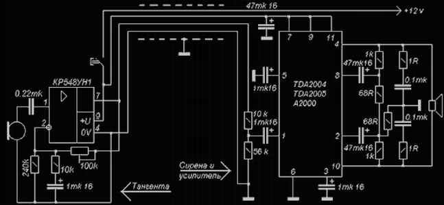
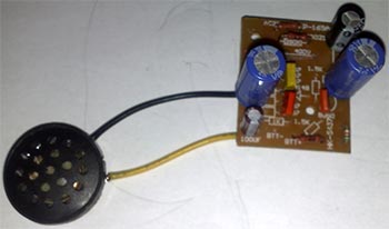
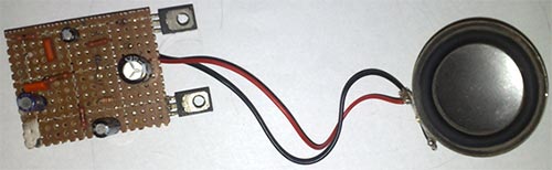
The circuit uses two ICs in a typical connection - KR548UH1 as a microphone amplifier (installed in the PTT) and (TDA2005) in bridge connection as a terminal amplifier (installed in the siren case instead of the original board). As an acoustic emitter, a modified alarm sipen with a magnetic head is used (piezo emitters are not suitable). Improvement consists in disassembling the siren and throwing out the native tweeter with an amplifier. Microphone - electrodynamic. When using an electret microphone (for example, from Chinese handsets), the connection point of the microphone with the capacitor must be connected to + 12V through a resistor ~ 4.7K (after the button!). The 100K resistor in the K548UH1 feedback circuit is better to put with a resistance of ~ 30-47K. This resistor is used to adjust the volume. It is better to install the TDA2004 chip on a small radiator.
To test and operate - with a radiator under the hood, and a tangent in the cabin. Otherwise, squealing due to self-excitation is inevitable. The trimmer resistor sets the volume level so that there is no strong sound distortion and self-excitation. With insufficient volume (for example, a bad microphone) and a clear margin of power of the emitter, you can increase the gain of the microphone amplifier by increasing the value of the trimmer in the feedback circuit several times (the one that is 100K according to the scheme). In a good way - we would need another primambas that does not allow the circuit to self-excite - some kind of phase-shifting chain or a filter for the excitation frequency. Although the scheme and without complications works fine
After mastering the basics of electronics, a novice radio amateur is ready to solder his first electronic designs. Audio power amplifiers tend to be the most repeatable designs. There are a lot of schemes, each differs in its parameters and design. This article will look at some of the simplest and most fully working amplifier circuits that can be successfully repeated by any radio amateur. The article does not use complex terms and calculations, everything is simplified as much as possible so that there are no additional questions.
Let's start with a more powerful scheme.
So, the first circuit is made on the well-known TDA2003 chip. This is a mono amplifier with an output power of up to 7 watts into a 4 ohm load. I want to say that the standard switching circuit of this microcircuit contains a small number of components, but a couple of years ago I came up with a different circuit on this microcircuit. In this scheme, the number of components is minimized, but the amplifier has not lost its sound parameters. After the development of this circuit, I began to make all my amplifiers for low-power speakers on this circuit.
The circuit of the presented amplifier has a wide range of reproducible frequencies, the supply voltage range is from 4.5 to 18 volts (typical 12-14 volts). The microcircuit is installed on a small heat sink, since the maximum power reaches up to 10 watts.
The microcircuit is capable of operating at a load of 2 ohms, which means that 2 heads with a resistance of 4 ohms can be connected to the amplifier output.
The input capacitor can be replaced with any other, with a capacitance from 0.01 to 4.7 uF (preferably from 0.1 to 0.47 uF), both film and ceramic capacitors can be used. All other components should not be replaced.
Volume control from 10 to 47 kOhm.
The output power of the microcircuit allows it to be used in low-power PC speakers. It is very convenient to use a chip for stand-alone speakers for a mobile phone, etc.
The amplifier works immediately after switching on, it does not need additional adjustment. It is advised to additionally connect the minus power supply to the heat sink. All electrolytic capacitors are preferably used at 25 volts.
The second circuit is assembled on low-power transistors, and is more suitable as a headphone amplifier.
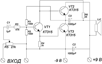
This is probably the highest quality circuit of its kind, the sound is clear, the entire frequency spectrum is felt. With good headphones, it feels like you have a full subwoofer.
The amplifier is assembled on only 3 reverse conduction transistors, as the cheapest option, transistors of the KT315 series were used, but their choice is quite wide.
The amplifier can operate on a low-impedance load, up to 4 ohms, which makes it possible to use the circuit to amplify the signal of a player, radio receiver, etc. A 9 volt battery was used as a power source.
KT315 transistors are also used in the final stage. To increase the output power, you can use KT815 transistors, but then you will have to increase the supply voltage to 12 volts. In this case, the power of the amplifier will reach up to 1 watt. The output capacitor can have a capacitance from 220 to 2200 uF.
The transistors in this circuit do not heat up, therefore, no cooling is needed. When using more powerful output transistors, you may need small heatsinks for each transistor.
And finally - the third scheme. A no less simple, but proven version of the amplifier structure is presented. The amplifier is capable of operating undervoltage up to 5 volts, in this case, the output power of the PA will be no more than 0.5 W, and the maximum power when powered by 12 volts reaches up to 2 watts.
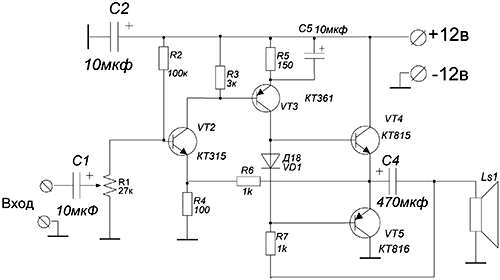
The output stage of the amplifier is built on a domestic complementary pair. Adjust the amplifier by selecting the resistor R2. To do this, it is desirable to use a 1 kOhm trimmer. Slowly rotate the knob until the quiescent current of the output stage is 2-5 mA.
The amplifier does not have a high input sensitivity, so it is advisable to use a preamplifier before the input.
A diode plays an important role in the circuit; it is here to stabilize the output stage mode.
The output stage transistors can be replaced with any complementary pair of appropriate parameters, for example, KT816/817. The amplifier can power low-power autonomous speakers with a load resistance of 6-8 ohms.
Good afternoon, dear habrauser, I want to tell you about the basics of building audio frequency amplifiers. I think this article will be of interest to you if you have never dealt with radio electronics, and of course it will be funny to those who do not part with a soldering iron. And so I will try to talk about this topic as simply as possible and unfortunately omitting some of the nuances.An audio frequency amplifier or a low frequency amplifier, in order to figure out how it still works and why there are so many transistors, resistors and capacitors, you need to understand how each element works and try to find out how these elements are arranged. In order to assemble a primitive amplifier, we need three types of electronic elements: resistors, capacitors and of course transistors.
Resistor
So, our resistors are characterized by resistance to electric current and this resistance is measured in Ohms. Each electrically conductive metal or metal alloy has its own resistivity. If we take a wire of a certain length with a large resistivity, then we will get a real wire-wound resistor. In order for the resistor to be compact, the wire can be wound around the frame. Thus, we get a wirewound resistor, but it has a number of disadvantages, so resistors are usually made of cermet material. This is how the resistors are electrical diagrams:The upper version of the designation is adopted in the USA, the lower one in Russia and Europe.
Capacitor
A capacitor consists of two metal plates separated by a dielectric. If we file for these plates constant pressure, then an electric field will appear, which, after turning off the power, will maintain positive and negative charges on the plates, respectively.
The basis of the capacitor design is two conductive plates, between which there is a dielectric
Thus, the capacitor is able to accumulate an electric charge. This ability to accumulate an electric charge is called electric capacitance, which is the main parameter of a capacitor. Electrical capacitance is measured in Farads. What is also characteristic is that when we charge or discharge a capacitor, an electric current flows through it. But as soon as the capacitor is charged, it stops passing electric current, and this is because the capacitor has received the charge of the power source, that is, the potential of the capacitor and the power source are the same, and if there is no potential difference (voltage), there is no electric current. Thus, a charged capacitor does not pass a direct electric current, but passes alternating current, since when you connect it to an alternating electric current, it will constantly charge and discharge. On electrical diagrams, it is designated as follows:
Transistor
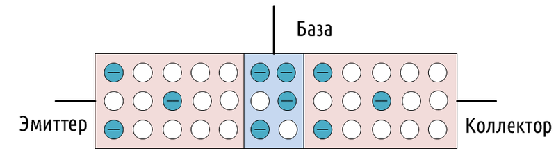
In our amplifier, we will use the simplest bipolar transistors. The transistor is made from a semiconductor material. The property we need for this material is the presence in them of free carriers of both positive and negative charges. Depending on which charges are greater, semiconductors are divided into two types in terms of conductivity: n-type and p-type (n-negative, p-positive). Negative charges are electrons released from the outer shells of the atoms of the crystal lattice, and positive charges are the so-called holes. Holes are vacancies that remain in the electron shells after the electrons leave them. Let us conventionally denote atoms with an electron on the outer orbit by a blue circle with a minus sign, and atoms with a vacant place by an empty circle:
Each bipolar transistor consists of three zones of such semiconductors, these zones are called base, emitter and collector.
Consider an example of the operation of a transistor. To do this, connect two 1.5 and 5 volt batteries to the transistor, plus to the emitter, and minus to the base and collector, respectively (see figure):
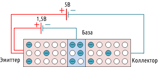
An electromagnetic field will appear at the contact between the base and the emitter, which literally pulls electrons from the outer orbit of the base atoms and transfers them to the emitter. Free electrons leave behind holes, and occupy vacant places already in the emitter. The same electromagnetic field has the same effect on the atoms of the collector, and since the base in the transistor is quite thin relative to the emitter and collector, the collector electrons quite easily pass through it to the emitter, and in much larger numbers than from the base.
If we turn off the voltage from the base, then there will be no electromagnetic field, and the base will act as a dielectric, and the transistor will be closed. Thus, when applying a sufficiently small voltage to the base, we can control a larger applied voltage to the emitter and collector.
The transistor we considered pnp-type, since he has two p- zones and one n-zone. There are also npn-transistors, the principle of operation in them is the same, but the electric current flows in them in the opposite direction than in the transistor we have considered. This is how bipolar transistors are indicated on electrical circuits, the arrow indicates the direction of the current: 
ULF
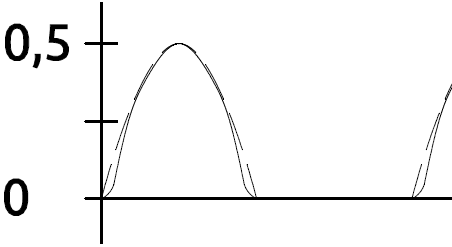
Well, let's try to design a low-frequency amplifier out of all this. To begin with, we need a signal that we will amplify, it can be a computer sound card or any other audio device with a line output. Let's say our signal has a maximum amplitude of about 0.5 volts at a current of 0.2 A, something like this: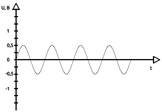
And in order for the simplest 4-ohm 10-watt speaker to work, we need to increase the signal amplitude to 6 volts, with a current I = U / R= 6 / 4 = 1.5 A.
So, let's try to connect our signal to the transistor. Remember our circuit with a transistor and two batteries, now instead of a 1.5 volt battery we have a line output signal. Resistor R1 acts as a load so that there is no short circuit and our transistor does not burn out.

But here two problems arise at once, firstly, our transistor npn-type, and opens only when the half-wave is positive, and closes when it is negative.
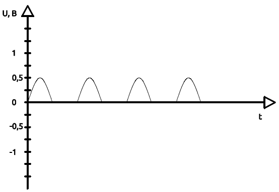
Secondly, a transistor, like any semiconductor device, has non-linear characteristics with respect to voltage and current, and the lower the current and voltage values, the stronger these distortions:
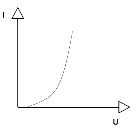
Not only is only a half-wave left of our signal, it will also be distorted:
This is the so-called step-type distortion.
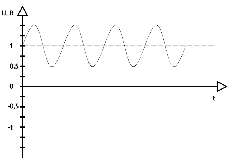
To get rid of these problems, we need to shift our signal to working area transistor, where the entire sinusoid of the signal will fit and the non-linear distortion will be insignificant. To do this, a bias voltage is applied to the base, say 1 volt, using a voltage divider made up of two resistors R2 and R3.
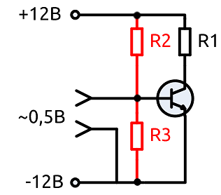
And our signal entering the transistor will look like this:
Now we need to remove our useful signal from the collector of the transistor. To do this, install the capacitor C1:
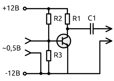
As we remember, the capacitor passes alternating current and does not pass direct current, so it will serve us as a filter that passes only our useful signal - our sinusoid. And the constant component that has not passed through the capacitor will be dissipated by the resistor R1. Alternating current, our useful signal, will tend to pass through the capacitor, so the resistance of the capacitor for it is negligible compared to the resistor R1.
So we got the first transistor stage of our amplifier. But there are two more small nuances:
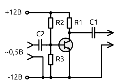
We do not know for 100% what signal enters the amplifier, all of a sudden the signal source is still faulty, anything can happen, again static electricity or a constant voltage passes along with the useful signal. This can cause the transistor to not work properly or even cause it to break. To do this, install the capacitor C2, it, like the capacitor C1, will block a direct electric current, and the limited capacitance of the capacitor will not allow high amplitude peaks that can ruin the transistor. These power surges usually occur when the device is turned on or off.
And the second nuance, any signal source requires a certain specific load (resistance). Therefore, the input impedance of the cascade is important for us. To adjust the input resistance, add resistor R4 to the emitter circuit:
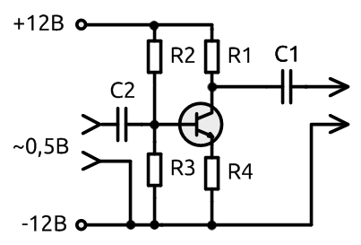
Now we know the purpose of each resistor and capacitor in transistor stage. Let's now try to calculate what values of the elements you need to use for it.
Initial data:
- U= 12 V - supply voltage;
- U bae~ 1 V - Emitter-base voltage of the operating point of the transistor;

- Pmax= 200 mW - maximum power dissipation;
- Imax= 100 mA - maximum D.C. collector;
- Umax\u003d 18 V - the maximum allowable collector-base / collector-emitter voltage (We have a supply voltage of 12 V, so there is enough with a margin);
- U eb\u003d 5 V - the maximum allowable emitter-base voltage (our voltage is 1 volt ± 0.5 volts);
- h21= 75-225 - base current amplification factor, accepted minimum value - 75;
- We calculate the maximum static power of the transistor, it is taken 20% less than the maximum dissipated power, so that our transistor does not work at the limit of its capabilities:
P st.max = 0,8*Pmax= 0.8 * 200mW = 160mW;
- Let us determine the collector current in static mode (without a signal), despite the fact that no voltage is applied to the base through the transistor, an electric current still flows to a small extent.
I k0 =P st.max / U ke, Where U ke is the collector-emitter junction voltage. The transistor dissipates half of the supply voltage, the second half will be dissipated by resistors:
U ke = U / 2;
I k0 = P st.max / (U/ 2) = 160 mW / (12V / 2) = 26.7 mA;
- Now let's calculate the load resistance, initially we had one resistor R1, which served this role, but since we added the resistor R4 to increase the input resistance of the stage, now the load resistance will be the sum of R1 and R4:
R n = R1 + R4, Where R n- total load resistance;
The ratio between R1 and R4 is usually taken as 1 to 10:
R1 =R4*10;
Calculate the load resistance:
R1 + R4 = (U / 2) / I k0\u003d (12V / 2) / 26.7 mA \u003d (12V / 2) / 0.0267 A \u003d 224.7 Ohms;
The nearest resistor values are 200 and 27 ohms. R1\u003d 200 Ohm, and R4= 27 Ohm.
- Now we find the voltage at the collector of the transistor without a signal:
U k0 = (U ke0 + I k0 * R4) = (U - I k0 * R1) \u003d (12V -0.0267 A * 200 Ohm) \u003d 6.7 V;
- Transistor control base current:
I b = I to / h21, Where I to- collector current;
I to = (U / R n);
I b = (U / R n) / h21\u003d (12V / (200 Ohm + 27 Ohm)) / 75 \u003d 0.0007 A \u003d 0.07 mA;
- The total base current is determined by the base bias voltage, which is set by the divider R2 And R3. The current set by the divider should be 5-10 times the base control current ( I b), so that the base control current itself does not affect the bias voltage. Thus, for the value of the divider current ( I cases) take 0.7 mA and calculate R2 And R3:
R2 + R3 = U / I cases= 12V / 0.007 = 1714.3 ohms
- Now we calculate the voltage at the emitter in the rest state of the transistor ( U uh):
U uh = I k0 * R4= 0.0267 A * 27 ohms = 0.72 V
Yes, I k0 the collector current is quiescent, but the same current also passes through the emitter, so that I k0 consider the quiescent current of the entire transistor.
- We calculate the total voltage at the base ( U b) taking into account the bias voltage ( U cm= 1V):
U b = U uh + U cm= 0.72 + 1 = 1.72 V
Now, using the voltage divider formula, we find the values \u200b\u200bof the resistors R2 And R3:
R3 = (R2 + R3) * U b / U= 1714.3 ohms * 1.72V / 12V = 245.7 ohms;
The closest resistor value is 250 ohms;
R2 = (R2 + R3) - R3= 1714.3 ohms - 250 ohms = 1464.3 ohms;
We select the value of the resistor in the direction of decreasing, the nearest R2= 1.3 kOhm.
- Capacitors C1 And C2 usually set at least 5 microfarads. The capacitance is chosen so that the capacitor does not have time to recharge.
Conclusion
At the output of the cascade, we get a proportionally amplified signal both in terms of current and voltage, that is, in terms of power. But one stage is not enough for the required amplification, so we have to add the next and the next ... And so on.The considered calculation is rather superficial and such a gain scheme is of course not used in the structure of amplifiers, we should not forget about the frequency range, distortion and much more.

