Star News


AC to DC. How diodes convert AC to DC.
Use in Everyday life various electrical appliances and devices that work thanks to electricity, obliges us to have a minimum knowledge in the field of electrical engineering. It is the knowledge that keeps us alive. Answers to questions about how to make alternating current from direct current, what voltage should be in the apartment and what modern person should know in order to avoid defeat and death from it.
Ways to get electricity
Today it is impossible to imagine your life without electricity. Every day, the entire population of our planet uses millions of watts of electricity to ensure normal life. But once again, turning on the electric kettle, a person does not think about what path electricity had to travel so that he could brew a morning cup of aromatic coffee.
There are several ways to generate electricity:
- from thermal energy;
- from the energy of water;
- from atomic (nuclear) energy;
- from wind energy;
- from solar energy, etc.
In order to understand the nature of the origin of electrical energy, consider a few examples.
Electricity from wind energy
Electric current is the directed movement of charged particles. The easiest way to get it is the energy of natural forces.
In this example, from wind energy. People have learned to use the natural phenomenon of wind blowing with different strengths for a long time. Taming the wind is a simple windmill equipped with a drive and connected to a generator. Generator and generates electrical energy.

Excess current with constant use of the windmill can be accumulated in batteries. The generated direct environmentally friendly current is not used in everyday life and production.
received and converted to alternating current, it goes for domestic use. The accumulated excess electricity is stored in batteries. In the absence of wind, the reserves of electricity stored in batteries are converted and supplied to human needs.
Electricity from water
Unfortunately, this type of natural energy, which makes it possible to receive electricity, is not available everywhere. Consider a method for generating electricity where there is a lot of water.
The simplest hydroelectric power station, made of wood according to the principle of a mill, the size of which is about 1.5 meters, is able to provide electricity used for heating, private subsidiary plots. Such a damless hydroelectric power station was made by a Russian inventor, a native of Altai - Nikolai Lenev. He created a hydroelectric power station that two grown men can move. All further actions are similar to obtaining electricity from a windmill.
Electricity is also produced by large power plants and hydroelectric stations. For industrial generation of electricity, huge boilers are used to produce steam. The steam temperature reaches 800 degrees, and the pressure in the pipeline rises to 200 atmospheres. This superheated steam high temperature and with great pressure enters the turbine, which begins to rotate and generate current.
The same thing happens in hydroelectric power plants. Only here the rotation occurs due to the high speed and volume of water falling from a great height.
Designation of current and its use in everyday life
Direct current is denoted DC. On the English language written as Direct Current. It does not change its properties and direction in the process of work over time. The DC frequency is zero. They designate it on the drawings and equipment with a straight short horizontal dash or two parallel dashes, one of which is dashed.
used D.C. in accumulators and batteries familiar to us, used in a huge number of different types of devices, such as:
- counting machines;
- Kids toys;
- Hearing Aids;
- other mechanisms.
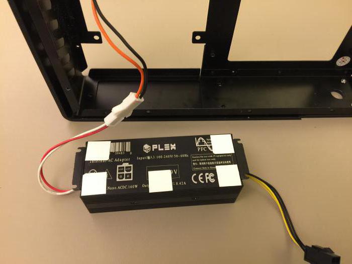
Everyone uses a mobile phone every day. It is charged through a power supply, a compact DC / AC converter, plugged into a household outlet.
Electrical appliances consume alternating single-phase current. Electrical appliances will work only with the connection of a transformer and Many manufacturers install a DC / AC converter directly into the unit itself. This greatly simplifies the operation of electrical equipment.
How to make alternating current from direct current?
It was said above that all batteries, batteries for flashlights, TV remote controls have direct current. To convert the current, there is a modern device called an inverter, it can easily make an alternating current from direct current. Let's see how it applies to everyday life.
It happens that while in a car, a person urgently needs to print a document on a copier. There is a photocopier, the machine is working, and by turning on the inverter adapter in the cigarette lighter, he can connect a copier to it and print documents. The converter circuit is quite complicated, especially for people who have a remote understanding of how electricity works. Therefore, for safety reasons, it is better not to try to build an inverter yourself.
Alternating current and its properties
While flowing, alternating current changes direction and magnitude 50 times in one second. The change in current movement is its frequency. The frequency is indicated in hertz.
We have a current frequency of 50 hertz. In many countries, such as the USA, the frequency is 60 hertz. There are also three-phase and single-phase alternating current.
For household needs, electricity equal to 220 volts comes. it effective value alternating current. But the amplitude of the current of the maximum value will be greater by the square root of two. Which will eventually give 311 volts. That is, the actual voltage of the household network is 311 volts. To change direct current to alternating current, transformers are used, which use various converter circuits.
Transmission of current through high voltage lines
All electrical outdoor networks carry alternating current of various voltages through their wires. It can range from 330,000 volts to 380 volts. Transmission is carried out only by alternating current. This method of transportation is the easiest and cheapest. How to make direct current from alternating current has long been known. Putting the transformer in the right place, we get the required voltage and current strength.
Converter circuits
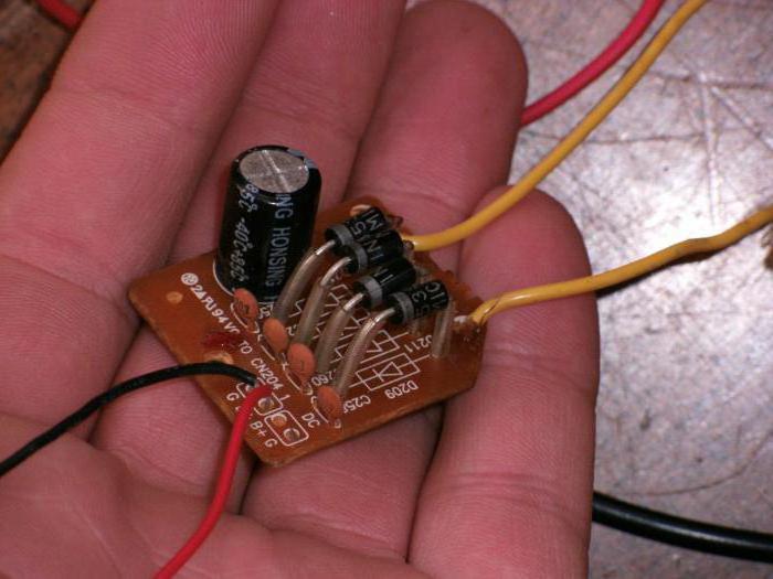
The simplest scheme for solving the question of how to make 220 V alternating current from direct current does not exist. This can be done by a diode bridge. The DC/AC converter circuit has four powerful diodes. A bridge assembled from them creates a current flow in one direction. The bridge cuts off the upper bounds of the variable sinusoids. Diodes are assembled in series.
The second circuit of the AC converter is to the output from a bridge assembled from diodes, a capacitor or a filter, which will smooth out and correct the dips between the peaks of the sinusoids.
Perfectly converts direct current into a variable inverter. Its scheme is complex. The parts used are not from a cheap order. Therefore, the price of the inverter is rather big.
Which electric current is more dangerous - direct or alternating?
In everyday life, we constantly come across at work and at home with electrical appliances connected to sockets. current running from electrical panel to the socket, single-phase variable. There are cases of electric shock. Safety precautions and knowledge of electric shock are essential.
What is the fundamental difference between AC and DC voltage? There are statistics that alternating DC single-phase current is five times more dangerous than direct AC current. Electric shock, regardless of its type, is in itself a negative fact.
Consequences of electric shock
Careless handling of electrical appliances can, to put it mildly, adversely affect human health. Therefore, you should not experiment with electricity, if there are no special skills for that.

The effect of current on a person depends on several factors:
- resistance of the body of the victim;
- stress that the person is under.
- from the strength of the current at the time of human contact with electricity.
Given all of the above, we can say that the action of alternating current is much more dangerous than direct current. There are experimental data confirming the fact that in order to obtain an equal result in the event of a strike, the direct current strength must be four to five times higher than the alternating current.
The very nature of alternating current adversely affects the work of the heart. Electric shock causes involuntary contraction of the heart ventricles. This may cause it to stop. Contact with bare veins is especially dangerous for people with a heart pacemaker.
DC has no frequency. But high voltage and current strength can also lead to death. It is easier to get out of contact with direct electric current than out of contact with alternating current.

This small overview of the nature of the electric current, its transformation should be useful to people who are far from electricity. Minimal knowledge in the field of the origin and operation of electricity will help to understand the essence of the work of ordinary household appliances, which are so necessary for a comfortable and peaceful life.
Author: elremont from 22-08-2013In this guide, I'm going to cover silicon diodes, diode bridges, and how to convert AC to DC. This is a symbol of the diode and pictures. The stripe at the end of a diode tells you how to put it in your circuit, but what is a diode?
A diode is a device that allows current to flow in only one direction. This is handy to remember when comparing diodes to faucets that only allow water to flow in one direction. So if you run AC voltage or current through the diode, the negative voltage will be blocked and you will be left with only a positive half wave. This process is called current rectification... it doesn't just work with sine waves. This will also work with square waves, triangle waves, or any other waveform that has a negative half cycle. Wait a minute...
If you increase and superimpose the signals on each other, you can see that the voltage has decreased! This is because there is no such thing as a perfect diode. All diodes have a forward voltage drop, denoted by "Vf". This means that whenever current flows forward through the diode, there will be a voltage drop, which is typically around 0.7 volts. The exact value depends on temperature, current and type of diode, but for now let's just assume it's 0.7V So a silicon diode won't even turn on until there's 0.7V across its terminals and there will always be a 0.7V voltage drop across the diode after it's turned on. Test it experimentally to see what I mean: With a negative input voltage, the diode can't turn on, so you don't get anything at the output. 0.3 volts at the input is still not enough to open the diode, so again you get nothing. 0.9 volts at the input is enough to open the diode, but due to the voltage drop, you will only have 0.2V left. And at 10 volts, minus 0.7 volts, you get 9.3 volts.
Sometimes the voltage drop across the diode is a problem... sometimes it isn't... As an example, I'll show you that at 10 volts peak-to-peak at the input, it's almost imperceptible.
But if I try to rectify a 0.5V current like the signal coming from my MP3 player, the 0.7V drop becomes a problem and it doesn't work. To cope with this problem, one must use advanced technologies such as super diodes. But for now, you don't have to worry about that. No device is 100% efficient, so let's talk about power. Will the diode heat up, can you predict? Well, the power loss in a diode is determined by Vf and the current flowing through the diode. For a typical silicon diode with Vf = 0.7 V, when passing one milliamp, only 0.7 mW is lost to heat, so this is not a problem. But already at 3 A, 2.1 W of heat is generated, which is quite a lot, so you will have to use a larger diode or use a diode with a low forward voltage drop, such as a Schottky diode. I will cover them in another video. Incidentally, no matter what anyone tells you, diodes in parallel will not be able to carry more current.
What happens if one diode closes? The heat that was generated on it will be released on other diodes. Old diodes are not perfect, but I want to talk about switching high speed diodes. I'm using 1N4007 diodes, they are designed for power electronics with low frequency AC 50 - 60 Hz, like in your house.
Now let's see what happens when I increase the frequency. After about 15 kHz, the diode becomes useless as it begins to conduct in the opposite direction. This is because it takes a certain amount of time for a diode to switch between open, allowing current to move forward, and closed. Different diodes will have different switching speeds. So, if I replace the 1N4007 with 1N4148, it will work well, up to 100 kHz and even more. To work with radio frequencies, you need to use diodes that switch even faster. So when you're designing something, you have to think about your diode's maximum reverse voltage, forward voltage, current rating, and switching speed. Google will always help you in finding reference information on diodes. It is good that in most cases it is not necessary to know the theory of how diodes work. So let's use diodes to build something. The most common use of diodes is to convert AC to DC, to power various devices that you have at home. I'm going to show you how to build a simple regulated source DC power supply is very similar to this one. I'll start with a low current and then I'll show you how to improve the design to handle a larger load. We start by converting the mains voltage to a lower, safe AC voltage. I'll show you how to do it in my Transformers guide. With no load, my transformer gives me a nice clean sine wave of about 39 volts peak-to-peak at 60 Hz. I installed a 1N4007 diode and measured the voltage before and after the diode, you can see the negative voltage cut off. Technically I converted AC to DC with only one diode because I removed all the negative voltage. But that's not a very good DC, is it? Half the time you have a weird voltage hump and half the time we have nothing at all.
If you need a little more stability to power your payload, we'll add a capacitor to set things right. I start with 1uF, but the more capacitance the better because you will have more energy storage. This is more like the truth! I now have an ideal 18.7 volt DC supply. Whenever you make a power supply constant voltage the best thing you can see on the oscilloscope screen is a constant stable voltage. Unfortunately, the only reason why everything looks perfect now is only because I didn't have time to connect the load. The capacitor is charging through the diode and there is nothing now to discharge the capacitor. So let's see what happens when I add a 4.7 kΩ resistor as a load. Ohm's Law predicts that there should only be 4 mA of load (which is very small), but look what happens. You see here that when the input voltage is positive, the diode allows current to flow, thus charging the capacitor. But as soon as the input voltage goes negative, the diode blocks the reverse flow of current and the only source of energy is the 1uF capacitor. And as you can see, its energy is quickly consumed even at low load. So what are we to do about it? Let's increase the size of our energy reservoir so that it is large enough to keep us powered until the next positive half wave. Let's replace the tiny 1uF capacitor with a large 470uF capacitor and see what happens.
It works very well! Now we have a DC power supply that can deliver a few milliamps of current which is enough to power some sensors and operational amplifiers. Okay, let's upgrade it up a notch. With a load of ten ohms, this circuit should draw much more current. Well, what the heck... we're back to the situation where the voltage sags in every beat. The average voltage is 8 volts, with a current of about 0.8 amperes, but the magnitude of the voltage ripple is huge. Imagine if we try to connect something to these... the voltage will constantly drop so low that it will never stay constant! So even 470 uF as an energy storage device is no longer enough. We can try to solve the problem head-on and add even more capacity.
So let's see how the circuit works with 3400uF. Well... that's better... Now we got an average voltage of about 12.5 volts with a current of about 1.25 A, but we see 5 volt AC ripples, which is a lot. You can keep adding capacitance indefinitely to reduce the amount of sag between cycles. But for a load of several amps, this becomes impractical and expensive. But there is a little trick. If we take four diodes and arrange them in this way, we get a "diode bridge". Here's how it works: In the first half of the sine wave, a positive sine wave arrives on the top wire, these two diodes turn on and let current through. Next, the diodes close, blocking any possible changes in the direction of the current. Now in the second half of the sine wave, where the top wire becomes negative with respect to the bottom wire, the other two diodes turn on and the other two turn off. So instead of losing the bottom half of the AC waveform by cutting it off and never using it, you just flip it and re-route it. And at the output you get a constant current with ripples of 120 Hz instead of 60 Hz.
And just like before, you can process the output signal with capacitors to get a nice smooth voltage. You can buy ready-made bridge rectifiers, but they are easy to build yourself. Here is my bridge rectifier connected to the transformer. I made it with four 1N4007 diodes and I spent about 4 cents on them. Take a look at how the voltage changes from positive to negative at 60 Hz, and now it never goes below zero volts, and we get these positive constant voltage half-waves at 120 Hz. This is called full rectification because we are using both AC waves. Now let's go back to our ten ohm breadboard and see how the bridge rectifier performs at 470uF compared to the single diode we tested earlier.
Now we have an average of 11.6 volts instead of 8 volts, which we used to get from one diode. And you can see that this is because the bridge rectifier charges the capacitor twice as often because we are using both half-waves of the 60Hz AC mains. Now think about how much of a difference that is, given that these extra diodes only cost me three cents.
Bridge rectifiers can be a little hard to understand, but because they work so well, everyone uses them. Now let's compare one diode with 3400uF and a bridge rectifier with 3400uF. Now we are averaging 13.5 volts instead of 12.5 volts and we only have ripples of about one or two volts. In other words, the combination of a large capacity bridge rectifier can convert high current AC power supply into a large usable DC power supply current. Just keep in mind that your diodes and capacitors must be rated for the voltage you are working with.
What we have now is basically what's inside those cheap little unregulated AC-to-DC power supplies that power radios, clocks, and other household gadgets. We could make a 9 volt version and it could power old Sega or Nintendo. But I want to emphasize that these are all unregulated power supplies. This means that even if we successfully smooth out the voltage ripple, we still face the problem of changing the average voltage under load.
With no load, it's 18.7 volts. And with 1 ampere load, you will get 13 volts. For some circuits this won't matter if they are designed to handle a wide range of voltages. But many devices such as microcontrollers and other digital electronics will require a very stable voltage source, and for this you will need to create a so-called regulated voltage source. I will talk about voltage regulators in another video. Now you know what diodes do and how they convert AC to DC.
_
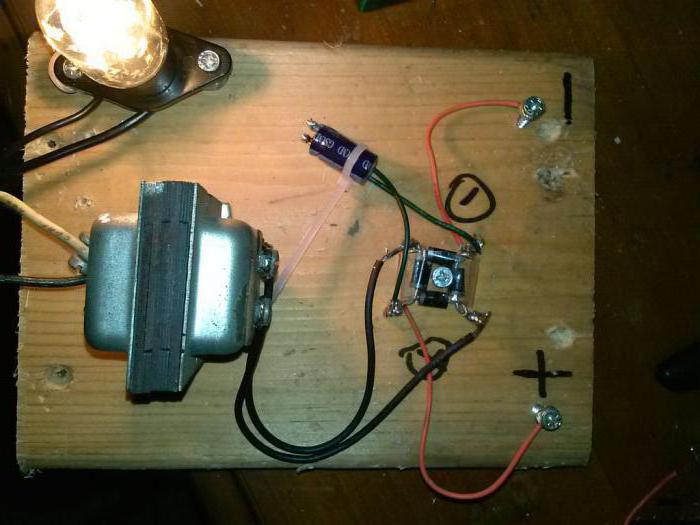
Power cuts in our homes, alas, are becoming a tradition. Does the child really have to do homework by candlelight? Or just an interesting movie on TV, that would be to watch. All this is fixable if you have a car battery. To it, you can assemble a device called a DC-to-AC converter (DC-AC converter in Western terminology).
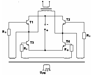
Figures 1 and 2 show two main circuits of such converters. The circuit in Fig. 1 uses four powerful transistors VT1 ... VT4 operating in the key mode. In one half-cycle of voltage 50 Hz, transistors VT1 and VT4 are open. The current from the battery GB1 flows through the transistor VT1, the primary winding of the transformer T1 (from left to right in the diagram) and the transistor VT4. In the second half-cycle, transistors VT2 and VT3 are open, the current from the battery GB1 goes through the transistor VT3, the primary winding of the TV1 transformer (from right to left in the diagram) and the transistor VT2. As a result, the current in the winding of the transformer TV1 is alternating, and during secondary winding the voltage rises to 220 6. When using a 12-volt battery, the coefficient K \u003d 220 / 12 \u003d 18.3.
A pulse generator with a frequency of 50 Hz can be built on transistors, logic circuits and any other element base. From the output DA1, pulses with a frequency of 50 Hz pass through two inverters on transistors VT7, VT8. From the first of them, the pulses are fed through the current amplifier VT5 to a pair of VT2, VT3, from the second - through the current amplifier VT6 to a pair of VT1, VT4. If transistors with a high current transfer coefficient ("superbet"), for example, such as KT827B or powerful field-effect transistors, for example, KP912A, are used as VT1 ... VT4, then current amplifiers VT5, VT6 can be omitted.
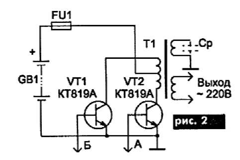
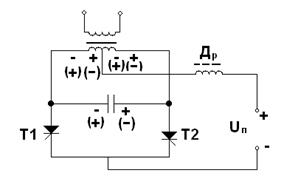
The circuit in Fig. 2 uses only two powerful transistors VT1 and VT2, but the primary winding of the transformer has twice as many turns and a midpoint. The pulse generator in this circuit is the same, the bases of transistors VT1 and VT2 are connected to points A and B of the pulse generator circuit in Fig. 1.
The operating time of the converter is determined by the battery capacity and load power. If we allow the battery to discharge by 80% (such a discharge is allowed by lead-acid batteries), then the expression for the operating time of the converter has the form:
T(h) = (0.7WU)/P, where W is the battery capacity, Ah; U - nominal battery voltage, V; P - load power, W. This expression also takes into account the efficiency of the converter, which is 0.85 ... 0.9.

Then, for example, when using a car battery with a capacity of 55 Ah with a nominal voltage of 12 V, with a load on an incandescent bulb with a power of 40 W, the operating time will be 10 ...
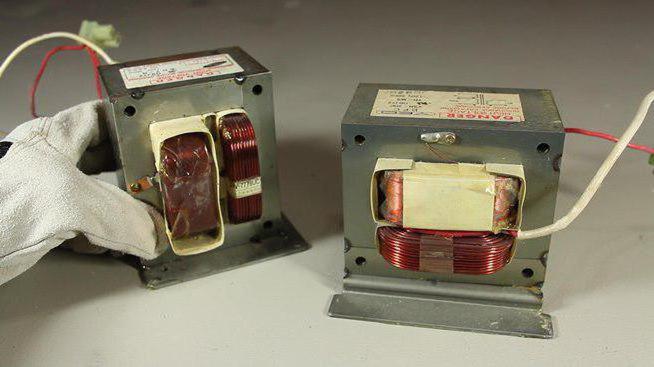
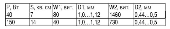
We give the data of the transformer T1 for two cases: for a maximum load of 40 W and for a maximum load of 150 W.
In the table: S - cross-sectional area of the magnetic circuit; W1, W2 - the number of turns of the primary and secondary windings; D1, D2 - diameters of the wires of the primary and secondary windings.
You can use a ready-made power transformer, do not touch the mains winding, but wind the primary winding. In this case, after winding, you need to turn on the network winding and make sure that the voltage on the primary winding is 12 V.
If you use VT1 ... VT4 as powerful transistors in the circuit in Fig. 1 or VT1, VT2 in the circuit in Fig. 2 KT819A, then you should remember the following. The maximum operating current of these transistors is 15 A, so if you rely on a converter power of more than 150 W, then you must either install transistors with a maximum current of more than 15 A (for example, KT879A), or turn on two transistors in parallel. With a maximum operating current of 15A, the power dissipation on each transistor will be approximately 5W, while without a heatsink, the maximum power dissipation is 3W. Therefore, on these transistors it is necessary to install small radiators in the form of a metal plate with an area of 15-20 cm.
The output voltage of the converter has the form of bipolar pulses with an amplitude of 220 V. This voltage is quite suitable for powering various radio equipment, not to mention light bulbs. However, single-phase electric motors with a voltage of this form do not work well. Therefore, it is not worth including a vacuum cleaner or a tape recorder in such a converter. The way out can be found by winding an additional winding on the transformer T1 and loading it onto the capacitor Cp (shown in dotted line in Fig. 2). This capacitor is chosen such that a circuit is formed that is tuned to a frequency of 50 Hz. With a converter power of 150 W, the capacitance of such a capacitor can be calculated by the formula C \u003d 0.25 / U2, where U is the voltage generated on the additional winding, for example, at U \u003d 100 V, C \u003d 25 μF. In this case, the capacitor must operate on alternating voltage (you can use metal-paper capacitors K42U or the like) and have an operating voltage of at least 2U. Such a circuit takes on part of the power of the converter. This part of the power depends on the quality factor of the capacitor. So, for metal-paper capacitors, the dielectric loss tangent is 0.02 ... 0.05, so the efficiency of the converter is reduced by about 2 ... 5%.
In order to avoid failure of the storage battery, the converter does not interfere with equipping it with a discharge indicator. A simple diagram of such a signaling device is shown in Fig. 3. Transistor VT1 is a threshold element. While the battery voltage is normal, the transistor VT1 is open and the voltage on its collector is below the threshold voltage of the DD1.1 microcircuit, so the signal generator audio frequency does not work on this chip. When the battery voltage drops to a critical value, the transistor VT1 turns off (the locking point is set by a variable resistor R2), the generator on the DD1 chip starts to work and the acoustic element HA1 starts to "beep". Instead of a piezoelectric element, a low-power dynamic loudspeaker can be used.
After using the converter, the battery needs to be charged. For charger you can use the same transformer T1, but the number of turns in the primary winding is not enough, since it is designed for 12 V, but you need at least 17 V. Therefore, in the manufacture of the transformer, an additional winding for the charger should be provided. Naturally, when charging the battery, the converter circuit must be turned off.
V. D. Panchenko, Kiev
"Belorussian State University informatics and radio electronics”
Department of Information Security
« ELECTRICAL CONVERTERS »
inverter- Converts direct current to alternating current.
Converter- DC to DC converter, but of a different level (with intermediate conversion of the input voltage to AC and transformation to the desired level).
The central link is a DC-to-AC converter.
Various schemes of such devices are used:
Transistor and electronic tubes;
Built on transistors with saturable cores;
Relaxation generators, triggers, multivibrators;
According to single-stroke, two-stroke and bridge circuits;
Thyristor simple and bridge circuits (in powerful devices).
A simple circuit of a push-pull thyristor inverter
Figure 1 - a simple circuit of a push-pull thyristor inverter
From T2, control pulses are sent to the thyristor circuit.
From a constant source, voltage is supplied to the input of the circuit. It goes through
on VD anodes. charged to double the input voltage. If we now apply pulses to VD2, VD1 immediately closes, recharges, all signs in T1 will change to the opposite and the current will flow through VD2.As can be seen from the operation of the circuit, on the switching capacitance
at the moment of closing the thyristor, a voltage equal to twice the supply voltage acts, which is a disadvantage for the circuit.It is eliminated by the bridge circuit of the thyristor inverter.
Bridge circuit thyristor inverter
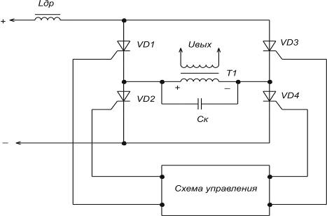
Figure 2 - Bridge circuit of a thyristor inverter
The control circuit first opens VD1 and VD4, and then, when the capacity is charged up to
, at this point, if you open other thyristors, VD1 and VD4 will instantly close.In this circuit, only the voltage of the power source acts on closed thyristors.
Thyristor rectifiers are efficient promising inverters. They are used at significant power and are currently used to replace electric machine units that convert DC energy of backup batteries into alternating current, in uninterruptible power supply devices (UGP) of equipment at communication enterprises.
DC voltage converters
Often when eating electronic devices IPs are low-voltage, and significant voltages are required to power the consumption circuits. In this case, voltage conversion is used. To do this, use inverters and converters. Electromagnetic transducers, vibration transducers and static transducers are used on p / n devices.
Electromagnetic converters generate a sinusoidal voltage, while semiconductor and vibration transducers produce a rectangular voltage. Currently, there are static converters with an output voltage close to sinusoidal in shape. The disadvantage of the electromagnetic converter: large dimensions and weight. Vibration transducers are low-power and unreliable. Therefore, semiconductor converters with small dimensions and weight, high efficiency and operational reliability are most widely used.
The construction of converters based on thyristors and transistors should be associated with the magnitude of the supply voltage, the required power, and the nature of the load change.
Transistor voltage converters
They are divided according to the method of excitation into 2 types: with self-excitation and converters with power amplification.
Transistors can be switched on according to the scheme with OE, OK, OB, but switching on with OE is most widely used, since in this case the maximum amplification of transistors in terms of power is realized and, moreover, self-excitation conditions are simply achieved.
Converters with self-excitation are carried out at powerful, up to several tens of watts, according to single-cycle and push-pull circuits. The simplest circuit single-ended converter is a relaxation oscillator with feedback.


With reverse diode. With direct incl. diode.
When the supply voltage is connected through a resistor, a reference potential is applied to the base of the transistor. The transistor opens and a current flows through the primary winding Wk of the transformer, which causes a magnetic flux in the magnetic circuits of the transistor. The voltage that appears on the winding Wk is transformed in the feedback winding Wb, the connection polarity of which is such that it contributes to unlocking the transistor. When the collector current reaches its maximum value: Ik \u003d Ib * h21e, the growth of the magnetic flux stops, the polarity of the voltages on the transformer windings changes to the opposite and an avalanche-like process of turning off the transistor occurs. The voltage on the secondary winding of the transformer has a rectangular shape.
The polarity of the rectifier power diode connected to the secondary side of the transformer determines how power is transferred to the load. The diode opens when the transistor closes, the capacitor is charged, which maintains a constant current in the load.
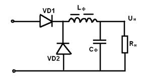
When the diode is directly turned on, the energy transfer of the power source Up to the load Rn occurs during the time period tu, when the transistor and the power diode VD1 are open. Energy is stored in the throttle W = 0.5 * Lf * In ^ 2 * tu. In this case, the smoothing filter capacitor Cf is charged by a rectified voltage up to Up.
During the pause tp, when the transistor is closed, the current circuit In is closed through the inductor Lf and the blocking diode VD2, as in a switching regulator with sequential regulation.
In single-cycle converters, the transformer operates with bias, which can be overcome by using a core with a charge. However, it does not fit when using tor. transistor. In our case, a blocking capacitor is used, which, during a pause tp, is discharged through the winding W1, remagnetizing the core with the discharge current.
Capacity Cbl. It is selected from the condition that at the maximum duty cycle φmax, the duration of the pause tp is at least a quarter of the period of the oscillatory circuit L, Cbl.
Such a diode reverse converter provides decoupling and protection of the output voltage from noise on the input power rails.
Transistor converters are determined by the following formulas:
Up \u003d Up (Ikm / 2In-W1 / W2)
tu \u003d Ikm * L1 / Up
tp \u003d Ikm * L2 / Un * W2
φ = fp*Ikm*L1/Up = tu/(tu+tp)
The best weight and size indicators have push-pull converters with a step-down transformer.
Transformers are made on a magnetic circuit with a rectangular hysteresis loop. Positive OS is also used here. The generator works as follows. When the supply voltage Up is turned on, due to the non-identity of the parameters, one of the transistors, for example VT1, starts to open and its collector current increases. The windings of the OS Wb are connected so that the EMF induced in them completely opens the transistor VT1 and closes the transistor VT2.
Switching of transistors begins at the moment of saturation of the transistor. As a result, the transformers induced in all windings. The voltages decrease to zero and then reverse their polarity.
Now, a negative voltage is applied to the base of the previously open transistor VT1, and a positive voltage is supplied to the base of the previously closed transistor VT2 and it starts to open. This regenerative process of forming the front of the output voltage is very fast. In the future, the processes in the scheme are repeated.
 The switching frequency depends on the value of the supply voltage, the parameters of the transformer and transistors and is calculated by the formula: fp \u003d ((Up-Uke us) * 10000) / 4 * B * s * Wk * Sc * Kc.
 This mode is more economical than when switching due to the limiting collector current and the operation of the converter is more stable.
Such converters are used as master oscillators for power amplifiers and as autonomous low-power power supplies. Main advantages: simplicity of the circuit, as well as insensitivity to a short circuit in the load circuit.
The disadvantage of a converter with a saturable core is the presence of collector current surges at the moment of transistor switching, which increases the losses in the converter.
The voltage across the closed transistor can reach the value:
Uкem \u003d (2.2: 2.4) Upmax
two voltages is the sum of Up + EMF on the idle winding, in addition, voltage surges during switching are taken into account. To reduce the latter, shunt diodes are sometimes included in the circuit.
When converting high powers, converters using a power amplifier are most widely used. Self-excited converters can be used as master oscillator. The use of such converters is advisable if it is necessary to ensure the constancy of the frequency and voltage at the output, as well as the invariance of the shape of the curve AC voltage when the converter load changes.
In the case of high input voltage, bridge power amplifiers are used.
 Let's assume that transistors T1, T2 work simultaneously in the first half-cycle. In the second T2, T3. The supply voltage is applied to the primary winding of the transistor, its polarity changes every half cycle. The voltage across the closed transistor is equal to the voltage of the power supply. The output transistor operates in an unsaturated mode, it is made of a material with a non-rectangular hysteresis loop.
 Thyristor converters
Thyristors, unlike transistors, have one-way control. To lock thyristors in converter circuits, reactive elements are used mainly in the form of switching capacitors.
 When the first thyristor is unlocked, the capacitance is charged to a voltage of 2Up. When the second thyristor is unlocked, the capacitor voltage is applied in the opposite direction to the first transistor, under the action of which it is locked. The capacitor is recharged, and the voltage on its windings and on the primary winding of the thyristor changes sign (the potentials are shown in brackets in the diagram). In the next half-cycle, the thyristor T1 is again unlocked and the process is repeated.
 To ensure the locking of thyristors, it is necessary that the energy of the switching capacitor be sufficient so that during the recharging process, the reverse voltage across the thyristors falls slowly enough to ensure the restoration of their locking properties.
The disadvantage of such an inverter is the strong dependence of the output voltage on the load current.
To reduce the influence of the nature and magnitude of the load on the shape and magnitude of the output voltage, circuits with reverse diodes are used, which, in turn, are necessary to return the reactive energy accumulated in the inductive load and reactive switching elements in the power supply of the converter.
Power supply with transformerless input
A feature of such sources is the use of the input voltage conversion process using a high frequency.
The absence of a power transistor at the input and the use of transistors at an increased frequency significantly improves the weight and size characteristics.
The functional diagram of the IPBV based on an adjustable converter has the following form:
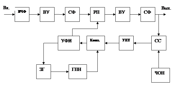
VChF - prevents penetration into the input circuits of interference from IPBV and vice versa.
VU - rectifier,
SF - smoothing filter;
RP - adjustable transducer;
ZG - synchronizing master oscillator;
GPN - sawtooth voltage generator.
The operation of the IPBV with input voltage stabilization using PWM is easy to imagine by considering the voltage diagrams in individual sections of the circuit.

In order to simplify the adjustment, the converter is usually built according to a single-cycle circuit with the recuperation of part of the energy accumulated in the reactive elements to the input voltage source. At the output of the converter at voltages of 5 - 10V, a rectifier with a midpoint is placed. In order to reduce the switching time of power transistors, circuits are used at their inputs that provide a significant excess of the blocking voltage with respect to the negative one.
LITERATURE
1. Ivanov-Tsyganov A.I. Electrotechnical devices of radio systems: Textbook. - Ed. 3rd, revised. and add.-Mn: Higher School, 200
2. Alekseev O.V., Kitaev V.E., Shikhin A.Ya. Electrical Devices / Ed. A.Ya. Shikhina: Textbook. – M.: Energoizdat, 200–336 p.
3. Berezin O.K., Kostikov V.G., Shakhnov V.A. power supply sources of radio-electronic equipment. – M.: Tri L, 2000. – 400 p.
4. Shustov M.A. Practical circuitry. Power supplies and stabilizers. Book. 2. - M.: Alteks a, 2002. -191 p.
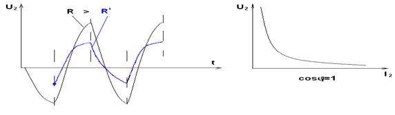
An AC to DC converter is a device that converts AC power to DC. This device is non-linear, so the voltage spectrum at its output is different from the input. In foreign literature, such devices are called AC / DC converters (alternating / direct current). Figure 1 shows the graphic designation of the AC / DC converter. At its input and output, oscillograms and voltage spectrograms are shown.
Figure 1. Conditional graphic designation of the rectifier
The AC/DC converter contains both a rectifier and a filter that suppresses unwanted output voltage components. The task of the filter connected to the output of the rectifier is to select only the constant component U 0 (useful effect of rectification) and suppress all other components of the voltage spectrum U d (ripple). This action is often referred to as "smoothing" the output voltage. Therefore, such a filter is called a smoothing filter. It is performed in the form of a low-pass filter (usually an LC filter) with a bandwidth Δ f f c .
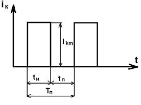
If the rectifier, which is part of the AC / DC converter, uses one half-wave of AC voltage during operation, then it is called single-cycle or half-wave, and if both half-waves are used, then push-pull or full-wave. Figure 2 shows a simplified diagram of a single-ended AC-to-DC converter.
Figure 2. Equivalent circuit of a single-ended AC-to-DC converter
In this figure, the key K synchronously with the frequency of the source U1 connects the load to the source. The load produces a pulsating voltage with a frequency ω c. During the period of the frequency of the input oscillation, only one current pulse passes through the load and the source. The frequency of the first harmonic of the current (and the ripple voltage on the load) is equal to the mains frequency ω c. The DC component of the load current in this circuit flows through the input voltage source. If a transformer is present in its composition, then this will lead to its magnetization and deterioration in weight and size parameters. If the mains voltage at the input of the half-wave rectifier is harmonic U 1 = U m sin ω c t, then the voltage diagrams at the input and output of this circuit will look as shown in Figure 3.
Figure 3. Timing diagrams of voltage at the input and output of a half-wave converter
As can be seen from this figure, the level of the DC component of the current at the output of the single-ended AC/DC converter circuit is quite small. Therefore, a two-stroke scheme is more often used. The diagram of a push-pull AC-to-DC converter is shown in Figure 4.
Figure 4. Equivalent circuit of push-pull AC/DC converter
In this scheme, the switches K1 and K2 connect the load for the time of one half-wave (T / 2) twice per period. Therefore, during the period of change in the mains voltage, two current pulses pass through the load and the source, and due to switching, the current flows through the load in one direction. The DC component of the load current does not flow through the primary source and does not affect its operation. The frequency of current and voltage pulses on the load U H is twice the mains frequency ω c, which makes it possible to reduce the dimensions of the smoothing filter. All of these factors can significantly improve the weight and dimensions of the AC to DC converter. Timing diagrams of voltages and currents at the input and output of a push-pull AC-to-DC converter are shown in Figure 5.

Figure 5. Timing diagrams of voltages and currents at the input and output of a full-wave converter
As keys in the circuits of AC-to-DC converters, uncontrolled and controlled valves are used, which are diodes, thyristors, bipolar and field-effect transistors. The most widely used are uncontrolled valves, which are used as powerful semiconductor diodes.
It should be noted that modern AC / DC converters are built according to a more complex scheme. They first rectify and filter the input oscillation, then generate a high frequency, the voltage of which is transformed into the desired one at the output, and then again rectify and filter all unwanted spectral components. This allows you to significantly reduce the size of the converter and increase its efficiency. Often they are made in the form of a small-sized one-piece block.
Figure 6. External view of the AC/DC converter
Literature:
- Sazhnev A.M., Rogulina L.G., Abramov S.S. “Power supply of devices and communication systems”: Tutorial/ GOU VPO SibGUTI. Novosibirsk, 2008 - 112 p.
- Aliev I.I. Electrotechnical reference book. - 4th ed. correct - M.: IP Radio Soft, 2006. - 384 p.
- Geytenko E.N. Sources of secondary power supply. Circuitry and calculation. Tutorial. - M., 2008. - 448 p.
- Power supply of devices and telecommunications systems: Textbook for universities / V.M. Bushuev, V.A. Deminsky, L.F. Zakharov and others - M., 2009. – 384 p.
- Denisov A.I., Zvolinsky V.M., Rudenko Yu.V. Gate converters in precision stabilization systems. - K .: Naukova Dumka, 1997. - 250 p.
Together with the article "Converting AC to DC" they read:
http://website/BP/Ventil/