Star News


Measurement of electrical insulation. Insulation resistance measurements. Measurements of insulation resistance of electrical wiring and their frequency of measurement
If you can spend a small budget on testing an electrical installation, then our company will help you with this. Insulation resistance measurement is the main type of measurement carried out by the electrical laboratory at a variety of objects. This type of measurement allows you to assess the condition of cables and wires. Checking the resistance and integrity of the insulation is included in any set of works of the electrical laboratory. Any controlling organization, in the very first place, when checking, requests a protocol for measuring insulation resistance. Measurement of insulation resistance can be carried out not only in the complex of services, but also separately.
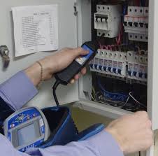
Testing insulation resistance with a shield
The test is carried out by stepping through each conductor, applying voltage and making a leakage measurement. This maximizes the probability of detecting an insulation defect anywhere in the cable. The total test time required for this increases directly with the number of conductors.
Measurements of insulation resistance of electrical wiring and their frequency of measurement
In most such cables, the capacitance between any live conductor and all other conductors on earth is approximately the same, and in the absence of insulation defects, the insulation resistance for each should be approximately the same. If the shield surrounds the conductors and must also be tested, the capacitance of the shield can be an order of magnitude higher than any single conductor, and the current during the rise will usually hit the breaking current before the test voltage is falsely reached, indicating a failure on the shield.
The assessment of the state of the insulation according to the legal regulations is carried out after a certain period of time. The cost of insulation resistance measurements does not depend on the frequency of their conduct. But such measurements may be required at any time. It is necessary to conduct them unscheduled in the presence of any adverse factors and suspicions of a malfunction of the electrical wiring.
We get very little by applying a voltage to the shield and measuring its leakage across all the other conductors, so simply programming the system to hold the shield at ground potential throughout the test eliminates this problem. We aim to find leakage between each conductor and shield, and as long as the conductor of interest is measured at high voltage relative to the grounded shield, we achieve this without applying voltage to the shield itself.
Potential danger when testing long cables at high voltage
For safety reasons, most hipo testers limit the maximum current generated by the equipment when low strength develops during testing. Thus, if the operator inadvertently comes into contact with exposed pins during the test high voltage, the current will not be sufficient to endanger the life of the operator. However, when testing long cables, we must also consider the energy stored in the cable.
The choice of an electrical laboratory, which will carry out the insulation test, must be approached responsibly. Don't just focus on prices. Equally important is the experience of the laboratory and the professionalism of its employees. Our company is a vivid example of the optimal choice - we offer professional services at attractive prices:
The results of the work on measuring the insulation resistance
As the test voltage increases, the stored energy increases with the square of the voltage. Accidental contact with an exposed pin at the far end of a long cable can, depending on conditions, be lethal, especially if a nearby person is unaware that a high voltage test is being performed. Care must be taken to close the ends of the cable and inform others about the test plans.
The presence of parasitic capacitance in cables longer than 10 feet requires longer measurement times to obtain an accurate reading of cable wires and insulation resistance. The inrush current that occurs at the beginning of the high voltage insulation test requires an adjustable ramp to prevent the maximum safe current limit of 5 mA from being exceeded. Increasing the voltage slowly to meet this requirement can greatly increase the test time.
- Measurement of insulation resistance we have 70 rubles for a line of 3 cores
- Measurement of insulation resistance price according to the TSN base 130 rubles per line of 3 cores
- Measurement of the loop phase-zero price according to the TSN base 400 rubles
- Measurement of the phase-zero loop, the cost is 129 rubles
- Checking a single-pole RCD price according to TSN 380 rubles
- Checking a single-pole RCD costs 210 rubles
- Checking a three-pole RCD price according to TSN 650 rubles
- Checking a three-pole RCD costs 239 rubles
- Measurements of insulation resistance price according to the TSN base 170 rubles per line of 5 cores
- Insulation resistance measurements cost us 100 rubles for a line of 5 cores
- Measuring the insulation resistance of machines price according to the TSN base 40 rubles
- Measuring the insulation resistance of machines, the cost is 20 rubles
- Checking the presence of a grounding circuit price according to TSN 60 rubles
- Checking the presence of a grounding circuit, the cost is 30 rubles
- Measuring the resistance of the ground loop price according to TSN 1500 rubles
- Measuring the resistance of the ground loop, the cost is 489 rubles
- Loading a single-pole machine costs 100 rubles
- Loading a single-pole machine price according to the TSN base 360 rubles
- Loading a three-pole machine up to 200A costs 180 rubles
- Loading a three-pole machine up to 200A price based on TSN 800 rubles
- Loading a three-pole machine up to 50A price based on TSN 510 rubles
- Loading a three-pole machine up to 50A costs 119 rubles
You can also determine the price of an electrical laboratory by the area and capacity of the facility. Depending on the number of electrical equipment and the type of economic activity of the object, 1 square meter equals 80-130 rubles. With the available capacity of the facility, the price of the electric laboratory is calculated based on the cost of 1 kW of power at 1000 rubles.
The tester must take great care when testing high voltages on long cables to avoid electric shock during testing due to a potentially lethal discharge current that can greatly exceed the current generated by the tester itself.
What are the standards and units of insulation resistance values for pure multilayer ceramic capacitors? Although the theoretical value of the insulation resistance of a capacitor is infinite, because the current between the insulated electrodes of the actual capacitor is smaller, the actual value of the resistance is finite.
You can order an electrical laboratory for an object right now by phone in contacts.
Order:
Insulation resistance measurement service in Moscow
Electrolaboratory EnergoServiceGarant» provides insulation resistance measurement services. Here you can order a measurement of the resistance of the sheath of cables and wires at competitive prices, which we will carry out at any residential, industrial and commercial facilities in Moscow.
Its set value changes depending on the capacitance value. Guaranteed insulation resistance value. As shown above, the higher the capacitance value, the lower the insulation resistance. The reason is explained below. Insulation resistance can be determined using Ohm's law of applied voltage, considering a multilayer ceramic capacitor as a conductor as well as an electric current.
Critical to this discovery is the availability of accurate and cost-effective effective means observations which, if not invasive, can provide early recognition and location of possible electrical degradation sites while the components are still in service. Maintenance can then be scheduled to avoid unplanned outages, interruptions, and inevitable loss of revenue. In the following examples, the instrument used has two different detection modes: spectrum analyzer and time resolution mode. The spectrum analyzer has three separate detection methods: peak detection, average detection, and split peak and average detection. Short bursts of impulsive accumulation alternated with long intervals of no or low energy activity. This mode also confirms the burst of the pulse train. However, impulse activity is more easily captured and lower energy impulses are detected. In each of these, the dynamic behavior of the activity is characterized by very short bursts of activity alternating with intervals of no or low energy activity. The sequence exhibits the characteristics of a floating type discharge. The secondary source of the discharge appears in the time-resolved trace. The measurements on the back of each circuit breaker were recorded and compared to the baseline. The observed rise in frequencies indicated a nearby discharge source, which was eventually triangulated to one particular circuit breaker by comparing the rise at higher frequencies as the receiving antenna was moved along the back of the switchboard. Repeated measurements on earth strips placed on adjacent circuit breakers indicate that said circuit breaker is the source of the measured discharge activity. An electromagnetic wave propagates along the outside of the casing, creating a transient ground voltage on the metal surface. The main emergency tank has been identified as the likely source of the discharge. The utility opened the switch and found signs of carbon at the end of the cable in the switchgear's main tank. They are subject to different kinds of duties plus a varied level of service. The technical tables at the start of each product family offer a direct comparison between tools. An explanation of important technical terms at the end of each section helps in the selection process. Power quality measurement is still a relatively new and rapidly changing field. There are currently hundreds of manufacturers around the world with unique measurement techniques. With so much variability between instruments, technicians often have to spend time understanding instrument capabilities and measurement algorithms instead of focusing on the quality of the power itself. It also defines the accuracy, throughput, and minimum set of parameters. In the future, manufacturers may start designing to Class A standards, giving technicians a level playing field and improving measurement accuracy, reliability and efficiency in the workplace. Examples of class A requirements: The measurement uncertainty is set to 1% of the declared input voltage. Low-cost power quality measurement systems with uncertainties greater than 1% may erroneously detect drops of -9% when the threshold is set to -10%. This is important when checking compliance with rules or comparing results between instruments or parties. Aggregation windows. The power quality tool compresses the received data in certain periods, which are called aggregation windows. By standardizing on 5 Hz bins and summing harmonics and interharmonics according to specific rules, Class A instruments will be consistent and comparable. To achieve accurate time intervals, external time synchronization is required, which ensures accurate data correlation between different instruments. Accuracy is specified with ± 20 ms for 50 Hz and ± 7 ms for 60 Hz instruments. 10 minute sync interval with 2 hour clock interval for sync. These new products include both handheld devices and devices designed to go to a fixed location for a user-defined period of time. Thus, there is a choice of products offering different possibilities from which the technician can choose the most suitable tool for the job. These new tools are designed for ease of use to identify intermittent and hard-to-find power quality problems. Suitable handheld analyzers will ensure that trends and captured events are displayed on the screen even while background recording is ongoing. Some of them can be used for interference analysis, incoming power validation, throughput testing before adding loads, and to evaluate power and power quality before and after upgrades. In some cases, however, it may be possible to restore this equipment to safe and reliable operation, thereby avoiding the need for costly replacements. The key to rescuing electrical equipment from flooding is to find ways to dry it efficiently without the risk of further damage. There are a number of options for this. Probably the most satisfactory is to use a temperature controlled oven with efficient air circulation, but in many cases this is not possible because the equipment is too large to move into the oven or because there is no oven. In these cases, infrared lamps may be used, or an enclosure may be built around the equipment, with steam coils or electrical elements used as the heat source. It is important to allow air to circulate freely so that moisture can escape and the use of blowers can be beneficial. Another method of heating sometimes used with devices such as motors and transformers is to run current at low voltage through the windings. Insulation testers that have ranges in kilograms are invaluable in this type of work. In some cases, welding machines are used as a power source for drying the windings. It is important to note that they are not designed to supply high currents continuously, so they should only be used at a fraction of their rated current. Whatever method of heating is used to dry out the equipment, it is very important to monitor the insulation resistance for a sufficiently long time to ensure that it remains stable. Very often, during the drying process, the insulation resistance rises to a relatively high value and then drops again. In fact, this rise and fall is often repeated several times as the moisture exits the equipment. Switchboards and electrical controls. Thoroughly clean and dry all equipment, dismantle where necessary. After drying, re-treat all coils. Check the contacts for corrosion and oxidation and ensure that all moving parts operate freely. - Drain all oil-filled devices, clean them and refill with fresh oil of the correct dielectric strength. The oil can be tested against British standards using a test kit. Dry all isolation barriers or replace if worn. Meters and protective relays usually need to be remanufactured by the manufacturer. To ensure a quick return to service, it may be preferable to match replacements. - Thoroughly clean and dry all busbar insulators and control wiring. A minimum of two megaohm insulation resistances must be reached before switching on the equipment, and this can be easily confirmed with any good quality insulation tester. - Test backup batteries for functionality with a battery resistance tester and check the battery tape for corrosion or excessive resistance using a specially designed low resistance ohmmeter. Electric tools and portable appliances. Many of the methods described in the introductory section of this article are suitable for disposing of wet tools and appliances. As an additional precaution, it may also be desirable to carry out explosion protection class 2 tests. Rotary electrical machines. Completely dismantle all parts and, with the exception of ball and roller bearings, and wash them with clean water or steam. Follow this with a thorough cleaning using a lubricant solvent. - Thoroughly clean all bearings and housings, paying particular attention to oil grooves and reservoirs. Disconnect and lubricate oil lines or steam clean them. - Remove the brush and clean the insulators. Some types retain water and must be dried very carefully. - Monitor the machine's insulation resistance with a state-of-the-art tester that uses low applied voltage for keel ranges. If this happens, they will need to be replaced. - Moisture may be affected in some slot wedge materials. The coils should then be tested for shorted turns with a digital low resistance ohmmeter. - After cleaning and drying, most windings will require re-lacquering. It is recommended to use cleaning and baking varnish, but its original varnish is in good condition, air-drying varnish can be used. - Before starting the machine, check the entire installation, paying particular attention to lubrication and electrical connections. For three-phase machines, check the phase rotation. Transformers - remove the inspection covers and check the condition of the windings, especially looking for signs of failure. Check all connections for looseness and signs of heating. With oil insulated transformers, pull oil samples from the top and bottom and test them with an oil test kit. Ideally, resistance should be comparable to pre-Flood values that can be accessed from records. Maintenance . If necessary, clean the outside of the transformer and paint the tank. - If water enters the tank, flush the windings with clean insulating oil. If necessary, dip and bake the windings. Windings for large transformers can be dried in the tank, forcing hot, dry air around the windings after draining the tank; by short circuiting one winding and turning on the other with low voltage; or using a combination of these methods. - During the drying process, record the insulation resistance curve over time, first measuring with a low voltage instrument, and then, if the process is successful, switching to a high voltage insulation tester. If the process is not successful and the curve does not show a steady increase in insulation resistance, the transformer will need to be rewound. - When the insulation resistance has reached an acceptable value, it is necessary to carry out a final test with the transformation ratio tester to confirm the transformer has been returned to full performance. Cables and wiring. All exposed wiring, including non-metallic sheathed cable, can usually be retained after the cable and junction boxes have been thoroughly cleaned and dried, and reconnected. - Armored cable usually needs to be replaced as it will drive the cable if the ends were underwater. - Rubber-coated cable in a rigid pipe can sometimes be reused, but it must be pulled out of the pipeline so that the pipeline can be cleaned. The piping must be thoroughly cleaned to remove all silt and moisture before reuse. - Check and clean hats and other insulators and inspect them for cracks or other damage. - Perform a comprehensive insulation resistance test before returning the unit to service. We hope that this article will provide a useful signal on the measures that can be taken to save electrical equipment after it has been flooded. However, it is important to remember that in every case, safety is paramount. This can only be ensured by thorough testing of scrapped equipment during and after repair using appropriate test equipment. Most electrical installations depend on earthing via earth electrodes for the protection of people and equipment. These installations require regular earth resistance testing, but most testing methods are either laborious, inconvenient, or prone to inaccurate results. However, as Pavel Svinerd from Megger explains, there is now a more efficient alternative. It is tempting to think that testing the resistance of a ground electrode should be no more difficult than finding a second ground, such as the nearest water pipe, and measuring the resistance between that and the electrode under test with a conventional ohmmeter. Unfortunately, life is not so simple. Noisy currents flowing in the ground will almost certainly cause large errors in the results obtained, and there is no way to know how much of the resistance is due to the secondary ground and how much it is itself grounded. In other words, some result will be obtained, but for all practical purposes it is meaningless. For this reason, a number of alternative methods have been developed to accurately measure earth resistance. The simplest is to make a direct measurement as described earlier, but with a specially designed ground tester that uses current alternating current . By choosing the frequency of this current, so it is not an integer multiple of the supply frequency, such an instrument can be arranged to provide a high degree of noise suppression. The results are much more significant than those that can be obtained with an ohmmeter, but there is still no way to confirm that they are accurate, or indeed separate the secondary earth contribution. A much better method, and one that is widely used, is commonly known as the three-terminal or potential drop method. This uses a connection to the electrode under test and two test spikes that must pass into the ground prior to testing. One of the spikes, the current spike, injects the test current and should be located as far away from the electrode under test as possible. Another spike - a voltage spike - is then driven into the ground in several places, preferably in a straight line, between the current and the electrode. Voltage is measured at each location. Because the current injected by the instrument is known, each of these voltage measurements can be converted, using Ohm's law, to a resistance value. In practice, this transformation is performed by the instrument itself. If a plot is plotted against the resistance versus the distance from the voltage peak from the electrode under test, it should have a certain plateau region where the resistance barely changes as the rod is moved. This resistance value is the required earth resistance for the electrode under test. This method is accurate and any measurement problems are obvious, as the resistance graph will deviate noticeably from the expected shape. The only drawbacks are that the test is time consuming to perform, it requires a reasonable amount of space, and that the earth electrode under test must be disconnected from all other circuits during the test. Those are pretty significant drawbacks. To provide a more convenient way to measure earth resistance, the clamp or dormant method has been adopted. This uses a tester designed to inject a test current into the earth electrode system through a clamping device and uses the same clamping head to measure the resulting current flowing in the electrode under test. No direct connections are required, and the ground electrode must not be disconnected from other circuits - indeed, there cannot be one for successful testing. Although this method is quick and easy, it has several limitations. It only works in applications where there are multiple parallel grounds so that there is a return path for the test current and therefore it cannot be used to test isolated electrodes. Since there is no way to verify the result, it is also unsuitable for testing in new facilities where previous test results are not available for comparison, but it is good for the trend of the earth system. A new solution, which is more versatile than the collisionless method and more convenient than the traditional potential drop method, is provided by an attached rod. However, there is one important difference - it is not necessary to disconnect the earth electrode from other circuits during the test. This may seem like a relatively small benefit, but aside from the physical hassle of breaking ground connections, it's important to remember that grounding is a safety feature. There are concerns about disconnecting the earth electrode as a fault current can flow and disconnection can result in a potentially lethal situation. In addition, if the equipment is disconnected from the earth electrode to allow testing, the equipment may be safer and dangerous situations may arise. While it is possible to provide temporary grounding or to cut off power during testing, such arrangements are likely to be both inconvenient and costly. The key is in the current measuring clamp, which is placed around the earth electrode under test. The tester is designed to ignore any system leakage and noise currents that may flow through the ground electrode. This means that it can accurately measure the test current despite interference. However, it still takes a long time, but there are a number of shortcuts that can be used in appropriate circumstances. For example, instead of taking readings with a voltage peak at different distances between the electrode and the current spike, sometimes it is enough to take several readings, with the voltage jumping up to 62% of the distance between them. In the event of an unexpected failure, this can lead to extended downtime, resulting in loss of operating income and costly repairs. Scheduled maintenance is the best insurance against transformer failure and this is where advanced diagnostic techniques come in. They offer an efficient, cost-effective way to assess the overall health of a transformer fleet so potentially hazardous areas can be flagged and action taken long before a potential failure becomes a major mistake. Also, if the operator has a transformer that is already a concern, then diagnostic tests can establish the severity of the problem, find the fault, and help the service team provide expert advice on what action to take. For example, with regular testing, a transformer can continue to operate at a safe, reduced load until the scheduled service interval is reached. However, for installed transformers, a field test can provide basic curves. An alternative approach is to use a generic comparison between similar transformers with the same design. Under certain conditions, design comparison can be used when comparing measurements between windings in the same transformer. It is much more specific than the low voltage impedance tests that are typically performed on transformers, helping to avoid catastrophic failures and can even find the exact location of the fault. The test determines the amount of moisture and the presence of contaminants in the solid insulation, as well as the conductivity and power factor of the oil. This is an extremely useful tool in a general condition assessment program as standard power factor tests alone do not provide this type of information. It is difficult to obtain a reliable estimate of moisture content by testing oil samples because water is transferred between the solid insulation and the oil as the temperature changes. An oil sample should be taken at relatively high temperatures when the transformer is in equilibrium. But this is a relatively rare transformer condition and can lead to unreliable estimates. In each case, the results of moisture tests in oils indicated the need for processing and drying of the oil. So our recommendation was to dry those two, leaving the five under close observation. The customer not only made very significant savings in operating and maintenance costs by preventing unnecessary drying operations on five transformers, but also reduced the risk of overdrying and weakening of the windings. The main purpose of this test is to check for significant differences between windings that may indicate field failure or damage, and to ensure that the transformer connections are correct and there are no major mismatches or open circuits. Oil sampling. Just as a blood test can provide a doctor with extensive information about a patient, a transformer oil sample can tell an engineer about the condition of a transformer, allowing them to effectively manage an asset for a long life and improve reliability. The role of oil in a transformer is to both cool it and insulate its internal components, and in doing so, it bathes every internal component. As a result, oil contains about 70 percent of the available diagnostic information for a transformer, and laboratory analysis can provide an early indication of a developmental condition, such as tweezer arc. The data obtained from an oil sample is only as good as the sample itself. This involves taking the sample warm and measuring the temperature so that the lab can then adjust the results for moisture content by first rinsing the sample sample and gently running the sample through a clean glass jar to minimize outgassing and seal the sample tightly. We recommend that the best information can be obtained from oil sampling by looking at trends. Therefore, it is useful to take a test mark sample when the transformer has been turned on or oiled, and then take additional samples at regular intervals so that any changes in quality can be measured to monitor the occurrence of errors. Typical tests performed in a laboratory analysis of an oil sample include: - Breakdown voltage - Moisture content - Dissolved gas analysis - Oxidation Each of these parameters affects other parameters, and they all work together to affect the condition of the transformer. In general, power transformers are very reliable devices and will provide excellent service for many years if they are serviced and maintained regularly. Failures, when they occur, are usually very serious and require costly repairs and the inconvenience of downtime. The best insurance against failure is a planned monitoring and testing regime. Expanding the Code of Practice by more than 50 pages, the revised publication provides much clearer guidance on all aspects of portable device testing, with the addition of a number of helpful illustrations. As an example, while the previous document gave detailed recommendations for testing mains plugs and cables, the revised version is supplemented by the inclusion of several illustrations showing typical faults that may occur. Similar clarifications and additional details are provided for all aspects of the verification and testing process. Has the new code changed the scope of the hardware to be tested? No, but he clarified some earlier points. For example, in the past, some types of electrical equipment, such as hand dryers, may be considered as an appliance by anyone testing an electrical installation, or as a fixed installation by anyone doing field testing. As a result, these items of electrical equipment may have remained untested. For those responsible for testing portable devices, this may require some modifications to the type of test instruments used. Alternative or replacement leakage is measured using a technique similar to that used for insulation resistance measurements. The resulting current is measured and then scaled to indicate the current that will flow at the rated supply voltage. The test voltage is current limited and therefore there is no danger to the test operator. Since the test voltage has the same nominal frequency as the mains supply, the creepage paths are similar to those found when the equipment is running. A calibration certificate is issued stating that the test instrument is within specification at the time the calibration is performed. This guide has been issued for new buildings, refurbished facilities, and portable diagnostic or treatment rooms in medical or healthcare facilities. The notes outline a number of measures to be taken with regard to the electrical supply and include new instructions regarding grounding and equipotential bonding of permanently installed medical devices and associated equipment. Anyone who touched these surfaces could then be struck or even killed depending on the current flowing through them to ground. Therefore, it is necessary to use equipotential bonding as part of the safety measures associated with electrical installations in order to prevent significant contact voltage in environment patient. In addition, it is stipulated that solid solid conductive wiring between the equipment and its associated mains insulator should not depend only on the continuity of conductors, cable braid, conduits or trunks, and should be achieved with a special copper earth cable connected to brass or copper fittings. The medical room requires an earthing panel that contains one or more copper bonding rods installed in the enclosure as part of the room's protective earthing system. This may include warning lights, jets, water baths, contrast agent warning equipment, viewing boxes and cabinets with medicines, including safety screens, metal sinks and work surfaces, heating pipes and radiators, water pipes, medicine cabinets, overhead equipment and other steel or wire cable trays, steel floor ducts and similar equipment. resistance, maximum allowable resistance equals 1 ohm. Anything above this level will constitute a failure to ensure ground continuity. This is because there may be some variation in the resistance of the pins, which may be manufacturer dependent. For this reason, it is suggested that the resistance of the connector be tested at the back of the inserted pin, rather than by probing the socket itself. There has also been a lot of controversy about the current and volume that should be used for this test. Traditionally, the standard tool used for equipotential bonding has been a mains powered unit capable of delivering up to 35 A at up to 25 V for a 5 second test. Tests have shown that a single ground wire can withstand the test, so is not a reliable measure of "reliability" by itself. Therefore, testing at lower currents is not necessarily a weaker test that will miss potential failures. The new manual means high performance grounding and equipotential bonding testing of medical devices and stationary equipment in the treatment room or diagnostic kit can now be done with lightweight, hand-operated digital micrometers. This tool uses the measurement of direct and reverse current with automatic averaging to maintain highly accurate measurement of very low resistance as well as the advantage of a battery, which means that equipotential bonding measurements can be taken without the risk of earth leakage currents from the main power supply interfering with resistance values. In addition, the tester can be used with extended test leads up to 20 meters without loss of measurement accuracy, making it easy to carry out retail tests available and allowing individual plug tests to be performed quickly and efficiently. Maintaining electrical integrity in medical environments is critical to preventing patient exposure to risk. However, finding these faults is often difficult and time consuming. Fortunately, there are many testing methods that make this task easier. The easiest way to find permanent faults today is in simple networks where the cable is known, such as the supply system for installing a street lamp. However, this does not mean that finding a fault is a trivial job. In fact, this can be extremely costly, especially for hidden cables. A better, more cost-effective technology is to use a structured approach to cable diagnostics and troubleshooting based on the use of state-of-the-art test equipment. The preliminary stage is simple: just perform continuity and low voltage checks to confirm the presence of a fault. However, one should not be tempted to expose the cable to high temperatures, as this may change the characteristics of the fault and make it difficult to locate and test later. The next step is to try to isolate the fault using a time domain reflectometer and standard pulse echo techniques. This instrument applies a short low voltage pulse to the cable under test and looks for voltages reflected back down the cable. Clear reflections in most cases are obtained due to short circuits and short circuits. By measuring the time it takes for the reflection to return to the instrument, a good indication of the distance to failure can be provided. It is always recommended to keep a test trace until further tests are done on the cable, as any change in fault status can be seen by real-time comparison with recorded traces. This has the advantage that a good circuit can be compared to a bad circuit, making it easier to interpret the results, as splices and cable ends will also contribute to their reflection on the trace. They have some limitations, but these inexpensive tools can find a high percentage of errors. Therefore, they are an excellent investment when buying more sophisticated equipment cannot be justified. This is sometimes necessary, but requires a different tool and depends on the type of cable, but may cause problems later in the troubleshooting process. A more complex option is to switch to the method of arc reflection of the damage site. This is due to sending a high voltage pulse down the cable, which causes a temporary arc at the fault location. The arc is instantly supported by the filter built into the arc deflection test kit. For this reason, Megger first developed a modified arc reflection method known as arc reflection plus. To do this, the test set sends a high voltage pulse to detect overheating in the event of a fault, and the test set's transient memory function is used to record the transients generated by the overflow. These transients travel back and forth through the cable with spikes that can be used to indicate distance to failure. In practice, the first reflected peak should be ignored due to the reionization period, but the time interval between the second and third peaks gives a good indication of the cable length between the test set and the fault. The methods described so far have one thing in common - they provide a measurement of the cable failure distance from the test set's connection point. Even if knowledge of the cabling is known, this is sufficient information to determine the distance of a fault, but not to detect a fault, since the cable rarely sits straight and level in a trench or channel. In many cases, accurate cable run information is not available. Therefore, a little extra work is required to determine the fault. To accurately determine the location of the fault, a method called exact is used. This cable fault detection method uses a surge generator—often referred to as a screener in this application—to apply high voltage pulses to the cable. These impulses lead to an overflow at the fault, which generates an audible noise - a blow. It also generates an electromagnetic field that can be detected by a suitable receiver. Sometimes the noise from the fault is loud enough to be heard without any additional equipment, but more often, especially with buried cables, a pinpoint is used. It's basically a sensitive ground microphone connected to an amplifier and headphones. The user simply moves the pinpoint along the cable until the impact is most clearly audible and the magnetic field is strongest. This must be the location of the damage. However, faults with cables in ducts can be difficult to find because sound can travel through the duct, making the listener less able to pinpoint the exact location of the fault. At the very least, it is easier and cheaper to replace a section of cable in a conduit than it is to dig up a straight buried cable. Despite the fact that many malfunctions in power cables are large resistance errors, when the impact technique is very useful, it is worth mentioning that not all cable faults will rumble. For example, short circuit errors do not overlap, so no electromagnetic field is generated, and since the pulse energy is not dissipated as sound, there is no place to find. That's why low voltage tests are applied first before conditioning causes a resistive error that can flare up, turning into a short circuit that doesn't get hit. No one will argue that finding faults on power cables is easy, but many types of test tools are now available. , which, when used in conjunction with a structured approach to troubleshooting, will assist in finding even the most intractable faults. The days of the black art of cable fault detection are over because it is now too expensive and too time consuming to go down this route. Since the errors themselves often lead to downtime and associated consequential losses, the money invested in the latest cable location equipment is money very well spent! Test and measurement - Power transformers - are you covered? It's easy to assume that the substation on your site belongs to a power utility, but are you absolutely sure? If you're wrong, says Megger's Damon Mount, and you're unfortunate enough to suffer a transformer error, you may find yourself landing with a bill worth tens or even hundreds of thousands of pounds. In a substation, power transformers are probably the most expensive items. And this is not the worst of them: the delivery time of a replacement transformer is usually months or even years for the most large types . Therefore, the direct and indirect costs associated with a transformer failure can be enormous. definitely no need to worry. All power transformers on your site are the responsibility of your power supplier, right? Might be a very good idea to check again. In a surprisingly large percentage of installations, the power transformers belong to the owner of the premises, not to the energy utility. Of course, there is still no reason to worry, because transformer errors will certainly be covered by insurance, they did not win? Because of the huge costs, insurers are understandably wary of claims related to transformer errors and failures. If there are claims, they will no doubt ask for proof that the transformer is regularly tested and maintained. Since many companies don't even know they are responsible for power transformers on their websites, it's not too much of a surprise, there are many transformers out there that certainly don't get the regular attention they need. This is a particular concern for many transformers currently in use that have a long kurtosis separated from their design lives. While they can apparently still work well, it is inevitable that some of the materials used in their construction, in particular the insulation materials, will begin to deteriorate. If an unsupported transformer fails, whether it's old or new, it's entirely possible that insurers will dispute the claim or refuse to pay. Let's see what needs to be done to avoid this potentially devastating situation. The first and most obvious step is to maintain departments to verify which of the transformers on their site are their responsibility. The next step will be to implement a regular testing program for these transformers. But which form should be tested? Of course, there are many traditional tests that can be applied to power transformers to verify, for example, the performance of tap changers or windings. This means that in order to create a sufficiently complete picture of the state of the transformer, a whole battery of tests is needed, which will take a significant amount of time to complete. During this time, the transformer will be taken out of service, which can be very inconvenient. However, there are two tests that in between can provide a wealth of information not only about the presence of flaws, but in many cases their type and location. These tests are an analysis frequency response sweep and frequency domain spectroscopy. A transformer consists of several capacitances, inductances and resistances. It is, in fact, a very complex circuit that creates a unique "fingerprint" when test signals are injected over a range of frequencies and the results are plotted as a curve. In particular, capacitances in a transformer are affected by the distance between the conductors. Thus winding movement, which may be caused by electrical overloads, mechanical shocks, or simply aging, changes capacitances and changes the shape of the frequency response curve. These curves are subsequently used as the basis for comparisons during maintenance or when problems are suspected. However, it is also possible to use type mappings between transformers with the same design. Finally, design comparison can be used in some cases when comparing measurements between windings in the same transformer. Medium frequencies from 10 kHz to 100 kHz represent axial or radial movements in the windings, while high frequencies above 100 kHz correspond to problems associated with wires from windings to bushings and switches. Of course, standard tests such as the widely used Karl Fischer test are available to accurately assess the moisture content of transformer oil, but that's not all. In fact, it is common for a much greater proportion of moisture in a transformer to be stored in a solid insulation such as paper than in oil. To further complicate matters, moisture moves between the solid isolates and the oil in a way that is affected by many factors, including but not limited to temperature. Thus, oil moisture measurement cannot provide reliable information on the moisture content of the transformer insulation. This is of great concern as moisture in the insulation greatly accelerates the aging process in transformers and furthermore it can cause bubbles between windings which lead to sudden catastrophic failures. To determine the moisture content of a transformer, the second of the previously mentioned tests, frequency domain spectroscopy, can be used. However, this time it is the dielectric property which is measured over a range of frequencies, typically from one millihertz to one kilohertz. In the first case, the oil needs to be repaired or replaced; in the second, the transformer needs only drying. A short circuit error on a transformer can cause invisible damage internally, and a damaged transformer brought back into service can suffer catastrophically. If the two traces match, nothing has changed and the transformer can be safely returned to service. This test takes less than an hour to complete, reducing downtime and saving money. Aging, mechanical damage, and moisture content can be seen as a change in the frequency response of a transformer over time, and may indicate that an action such as transformer drying out needs to be corrected to protect against future failures. In other cases it may show that the transformer is inevitably nearing the end of its useful life, but even then the information is invaluable. In this situation it may be possible, for example, to minimize the load on the transformer so that it can continue to operate until a replacement is obtained. And even in the worst case, there is at least a warning that failure is inevitable, which can give time to create contingency plans and put them into action. There is another very valuable aspect of regular testing that we touched on earlier. Insurance companies are more likely to comply with failure claims on a power transformer that has been regularly inspected and properly maintained to fix any problems found through testing. Such a transformer is of course less likely to fail, but if it is at least a consolation that insurers will pay the bill! Even to those who are aware of their responsibilities when supervising power transformers, regular testing can seem like a bit of a burden. However, tests can be carried out using modern instruments quickly and easily, and they give reliable informational results. Sampling and product verification tests are primarily designed to determine type tests and assembly instructions that are supported by a set of "working standards" and rely on a traceable scientific relationship between the "sample" and the rest of the batch. Assuming that if the sample shows compliance, then the rest of the parties also comply. customer safety is paramount, can anyone take this risk? In order to maintain a proper scientific relationship, back to "approved product" trial lot testing should indeed involve repeating a "type test", which may involve using an external test house or submitting the sample to a dedicated, in-house testing laboratory. Using a typical sampling procedure as an example, the following scenario can be envisaged: A risk analysis defines a procedure for testing one sample of product for every 100 that exit the assembly line. The sample is sent to the laboratory where it is subjected to rigorous testing and fails. Strictly speaking, production should be stopped until the cause and extent of the fault can be identified. The cost of this exercise can be worked out in terms of callback costs - even more so if products have left the factory - testing costs, recycling costs, lost production, and late delivery penalties. Likewise, it is clearly in the interests of finished product manufacturers that critical safety components are used to assemble the product, preferably before incorporation into the product. Many manufacturers are now requesting "certificates of conformity" from their suppliers of critical safety components. However, the question should always be "how confident are you in your test mode?". Against this backdrop, it is clear that there is a growing number of electrical product manufacturers who want to test supplied components before or during assembly of their own product. Among such companies, there is a recognition of the benefits that can lead to proactive identification of problems and defects before assembly, increased confidence in the finished product, reduced likelihood of product re-work, and making supplier abandonment costs easier. By completing the cycle with 100% product testing, significant information can be collected and used to improve and refine processing and processing methods. Identifiable causes of product failures can be isolated and quickly addressed. Even simple error counters can indicate specific areas of the build phase that may require further investigation. Another major benefit to 100% testing is the development of a competitive advantage, as the company's ability to offer full testing during in-house manufacturing processes reduces the customer's need for in-house testing, thus offering a level of added value that can be translated into higher profitability, plus credibility. customers and loyalty. But what does 100% testing mean? First, it should be noted that we are talking about electrical safety requirements. A number of criticisms have been made against 100% testing, again generally based on time and cost. As for the time factor, problems usually arise from misconceptions about type testing requirements and established practices for 100% standard production line testing. A typical electrical safety test mode to meet these routine test requirements can be completed in less than five seconds. Going back to an earlier example, all 100 products could be tested in less than nine minutes. In terms of cost, equipment can be expensive if a type test requirement is to be used. However, for routine testing of a production line, there are a number of systems available that can cost as little as £. With easy-to-use setup and control features, they can be easily incorporated into a production environment without the need for a highly skilled workforce. For tests like the flash test, it may require high current levels and extended test times, and therefore this type of test may need to be applied under strict control conditions, including the use of highly qualified and experienced personnel. However, for standard production line testing, electrical safety standards not only define a lower safe shutdown level, but also a test zone setting that is well defined to ensure operator safety. Experience shows that conventional test parameters provide a realistic assessment of electrical safety and are not detrimental to equipment designed to meet relevant standards for leakage, clearances and insulation properties. Time and money aside, 100% electrical safety testing on a production line makes sound economic and business sense, creating competitive advantage and peace of mind. However, thermal imaging has recently been proposed as a simple and effective solution in many of the same applications. But is it? Low resistance is a well-established method that can be used almost anywhere electrical conductivity is important. Its applications range from testing the quality of earth bonds to testing the density of graphite electrodes in aluminum smelters. The real answer is that both low-resistance testing and thermal imaging have their place, so in order to decide where to use, let's take a look at the strengths and weaknesses of each. The great advantage of low resistance testing is that it can detect problems even if there is no current present in the object under test, making it very suitable for applications such as welding quality testing, lightning bond performance testing, aircraft structural integrity testing, and testing of grounding systems. Testing is also invaluable in manufacturing applications, especially when it is necessary to test subassemblies rather than complete systems, and to test new or retrofit electrical installations before power is applied. Thermal imaging is hardly suitable for any of these applications. low-resistance testing is that it provides simple quantitative results that can be easily recorded and, even more usefully, a trend as part of a predictive maintenance program. Having said that, low resistance tests of course have their limitations. For example, it cannot be used on live hardware. Therefore, for equipment that is in operation, it is necessary to organize a power supply department before the test, which is not always convenient. if there are many connections to test, low resistance testing can take a long time. Turning now to the thermal imager, this is a good way to check for overloads and unbalanced loads that cannot be done with a low resistance tester. Thermal imagers also have non-electrical applications, such as finding heat loss from a building and detecting mechanical problems such as worn bearings in a motor that get hot due to excessive friction. Thermal imaging also has a reputation for being easy to use, but this is not always the case, the operator must understand what they are seeing and can interpret the results. For example, is the transformer overheating or is it at normal operating temperature? What is the load on the equipment during the test? At what point does temperature rise become a problem? In high voltage environments such as an electrical substation, another complication is that it is often unsafe to get close to the equipment to see it clearly. Also, items such as fuses and circuit breakers are usually installed in metal cases, and thermal imaging will not work through metal. It is often not safe to remove covers or open doors while the power is on, but by the time the power supply is isolated and the covers are removed, the equipment will have cooled significantly, making thermal imaging data suspect. Finally, trending thermal images for identifying changes over time are not particularly straightforward. Thermal imaging, as we have seen, is a very useful technique, but it complements rather than replaces low resistance tests. And there are many applications that will do nothing but a low resistance test. However, he places little emphasis on choosing a low-resistance test set if it offers maximum versatility and convenience. Therefore, it is important that the tool is properly protected. In many test suites, this protection is provided by a fuse, but this is not particularly convenient because if a suitable replacement is not available, the tool cannot be used until a replacement is obtained. With these tools, testing can be done normally once the corrected power has been properly isolated. It is also important to select a tool that can provide a test current appropriate for the application - ideally it should offer a selection of test currents covering a wide range. This is because high test currents may in some cases lead to undesirable heating of the sample, while in other cases the heating caused by high currents , is indeed desirable as it can help identify weak points such as broken strands in a multi-core cable. Similarly, the usefulness of low test currents also depends on the application. Low currents can be a problem in some circumstances as they don't cut through the fouling in the connections. In other circumstances, however, this can be beneficial as the same situation can be a useful indicator that contamination is present! In addition, the low test current combined with varying test current can eliminate the need for temperature compensation of results, and also has the advantage of extending battery life in portable instruments. Finally, ease of use is the deciding factor. For maximum ease of daily use, a test suite must have an intuitive user interface, and it must execute tests quickly and efficiently, otherwise it will quickly become a constant source of annoyance rather than a useful tool. In conclusion, it is clear that both thermal imaging and low-resistance testing are invaluable techniques, and the ideal situation is to have access to test equipment for both. Only then can you be absolutely sure of giving the definitive answer to the question we've all asked at one time or another - is your resistance low, or are you getting hot? Test and Measurement - Improve the efficiency of test data management. Advances in technology make everything faster, smarter and smaller, and computer programs that simplify data management for greater efficiency, the needs of those contractors and engineers involved in test and measurement work, have never been better satisfied. All of these advances were made with the need for improvement in mind, as well as so that they could add value to the testing process. The result is not only more efficient work efficiency, but also improved relationships with customers and end users, creating important new business opportunities in the process. With the ever-present need to conduct inspection and testing quickly without compromising quality, the link between measuring equipment used in the field and central test record systems that provide test certification and other test reports is becoming increasingly important. Unlike simple "electrical testers", in a broad sense, the most advanced 17th edition testers and portable instrument testers can now be seen more as test data collection tools - the collection of important measurements and checks made on electrical systems and equipment. there is now more focus on the ability to improve the transfer of this data between the tester and the database - and especially on how the collected data was received, interrogated, processed and presented for better control of security testing programs. The software allows the recording of electrical installation and control data directly by the tester using a copy of the inspection and test certificate that is displayed on the instrument. After collecting all validation and testing data, the onboard software scans the certificate and warns the user that any fields are incomplete or invalid. The integral "certificate helper" also contains many of the commonly used table values, such as ground loop impedance tables, avoiding the need to take voluminous reference material on site. latest version This program allows test results from larger individual sites, such as shopping malls or commercial office complexes, to be combined into one certificate. Another new feature is the ability to "clone" certificates from an existing master document. This allows the user to select an existing certificate and use it as a template to create multiple certificates for identical or similar electrical installations - such as the type needed to develop housing of the same type of properties and electrical systems. Same software products can also be used to create asset registers for clients, print test certificates, and output test reports in a variety of formats. Dedicated time manager software provides clear information about the test activity of individual users and engineers - providing details such as test time, number of tests performed, and time between tasks. Analyzing this information allows service or contract managers to understand how often testers are used, identify improvements in staff training, and help field staff check work faster and work more efficiently. The pre-trigger feature allows re-test schedules to be counted before instruments are overdue for testing, with special email alerts sent by customer contact personnel to provide advance warning of any potentially hazardous electrical equipment in the workplace. The system can also be configured to send official retest price quotes with full schedule planning and costing alerts, incentives for repeat business, and improved customer support. For all types of electrical test and measurement activities, the combination of innovative test and measurement equipment with sophisticated record-keeping programs provides real practical benefits to contractors - reducing costs, increasing revenues and increasing productivity. In recent years, the tool industry has been at the forefront of innovation and technological advancement. These changes were made in recognition of the situation for electrical companies, especially in a challenging economic environment, the challenge is to balance the provision of efficient, high quality test services with competitive pricing and bidding. Test companies that thrive will be those that combine a fast and efficient service that does not compromise the quality of the testing that is being done, and who can build on existing customer relationships. In fact, customer service and satisfaction has become an important area for electrical testing companies. With less stress on existing relationships become even more important. It follows that the ability to improve existing customer services through the provision of a cost-effective and complementary test service can go a long way towards strengthening a company's reputation and maintaining a positive profile with influential prospects. In addition, as is the large number of testers available, the ability to provide seamless communication between test tools used in the field and central test record systems that produce test certification and other reports is also of even greater importance. The note defines three main categories of measuring instruments: those that measure voltage, as well as those that measure current, resistance, and inductance and capacitance. The first named is an integral part of the procedure for checking the system dead before starting work, while the other categories are more concerned with commissioning and testing procedures and diagnostics. This is for practical reasons in terms of using one meter all the time rather than swapping and swapping between testers, and also for budgetary reasons - buying, maintaining and calibrating one combination tester is always cheaper than buying three separate ones. Some testers are also connected to smartphones and portable portable applications for laptops that work in the same way, by collecting test data collected in the field for later transfer to the main certificate. The latest release 17 generation testers eliminate the use of intermediate devices by storing a replica of the test certificate in the test, so test data can be automatically included in the certificate when testing is performed. Thus, the instrument combines the functions of a multifunctional measuring instrument and a data logger. Also, because the tester alerts the user when any certificate fields appear incomplete or invalid, data validation can be done on the spot immediately and without return visits. Recently, the concept of "on-board certification" in testers has been expanded with additional features designed for large test organizations or testing large rooms. This is particularly useful in situations where a number of experienced employees may be working on the same large facility, such as a hospital or shopping mall, and makes it very easy to assign specific test jobs to a number of engineers. Once the testing has been done, the software allows you to test the results downloaded separately from different testers to be combined into one certificate for the respective premises. This allows the user to select an existing certificate and use it as a template to generate multiple certificates for identical or similar electrical installations. The cloned certificates will contain everything switchboards and circuit details stored in the original, and therefore represent an easy way to create certificates on, for example, 20 or more houses on a street that share the same electrical configuration. With such a wide range of test tools and accessories to choose from, electricians and contractors involved in 17th edition testing can rest assured that the right test package solution is available to meet their specific needs and budget. This approach, however, is far from ideal. The first problem is that, in most cases, control engineers are not defensive engineers. Therefore, they are unlikely to be familiar with the operation of the protective relay test kit. Sure, they can learn, but it's a pretty steep learning curve for something that isn't central to their job. Another problem is that relay protection test kits are expensive because they include high performance precision amplifiers and other items that are expensive to design and manufacture, but they are not needed to test interlock circuits, so using the relay test set in this application, not only redundantly but uselessly ties up expensive capital equipment. Basically, it's not hard to imagine how such a test suite would work. The test set could also work in the opposite direction. Essentially, this kind of test suite is just an interface between Goose's messages on the bus and the electromechanical world of the controller engineer. Of course, there is much more than this basic overview should initially assume. In practice, sub-millisecond conversion times achievable with careful design will be fast enough to meet the most demanding requirements. Additional clarifications may also be provided. The gauge required will depend on the level of current being conducted; for example, cables that need to carry 40A probably need 12 gauge cable. Check the "Maximum Amplifiers to Connect to Chassis" column to find the conductor needed to provide the current level. A low-strength cable is critical to prevent damage to the instrument. Keep cable length as short as possible and always use low inductance, high gauge cable to limit voltage drop across wires. While many believe that guarding can minimize the effects of cable charging, this is generally more of a concern for high voltage testing than for high precision testing. The sockets used on the test equipment must be of high quality. For example, some red jacks use large amounts of iron to produce a red color, which can lead to unacceptably high levels of leakage due to conduction. When pulsing a large amount of current through these devices, they tend to oscillate. Inserting a gate resistor will attenuate these fluctuations, thereby stabilizing the measurement; because the gate doesn't draw much current, the resistor doesn't cause a significant voltage drop. Many electrical test systems or instruments are capable of measuring or selecting hazardous voltage and power levels. It is also possible, under single failure conditions, to output dangerous levels even if the system indicates no danger. These high levels make it necessary to protect operators from any of these hazards at all times. Protection methods include: - Check Before putting it into operation, carefully check the test setup. - Design test fixtures to prevent the operator from coming into contact with any dangerous circuit. - Ensure that the device under test is completely enclosed to protect the operator from any flying debris. - Double insulation of all electrical connections that the operator may have touched. Double isolation ensures that the operator is still protected even if one of the layers is isolated. - Use highly reliable fail-safe interlock switches to disconnect power supplies when the cover of the tester is opened. - Where possible, use so that operators do not require access to the inside of the test instrument or have to open protective devices. - Provide proper training to all users of the system so that you understand all potential hazards and know how to protect yourself from injury. It is the responsibility of designers, integrators and installers of test systems to ensure the protection of the operator and maintenance personnel. The frequency traces show a discrete form as the pulses are accumulated. . When an insulated cable enters the job site, the recipient must be able to confidently assume that it will reach its specified service life.
The cores in an electrical cable are separated from each other by a special insulating sheath, the resistance of which, ideally, should be infinite. But in practice, there is a leakage current between live conductors, therefore, with the deterioration of the insulating properties of the cable sheath, fires and short circuits can occur. , carried out in a timely and regular manner, allows you to avoid the occurrence of unpleasant situations.
Insulation resistance measurement frequency
The frequency of measuring the resistance of the cable sheath, according to clause 62.2.1 of GOST 50571.16-2007, is a time interval that is determined by the consumer of the electrical installation. But in Appendix 3.1 of the PTEEP, this time interval is specified: it says here that it is necessary to measure the resistance of electrical wiring in outdoor installations and especially dangerous premises annually. At other sites - once every three years.
Carrying out measurements of insulation resistance - features
Measurement of the resistance of the cable sheath is carried out with a special device - a megaohmmeter. This device generates a given voltage and measures the level of resistance.
The method for measuring resistance is quite simple. It consists of three stages:
Megohmmeter generates measuring voltage.
The device determines the leakage current that passes between the conductors.
The resistance of the insulating sheath is calculated, which is a quotient of the listed values.
It should be noted that the number of measurements may differ depending on the number of conductors in the cable. For example, if the cable consists of:
from the phase and neutral wire, only one measurement is carried out;
from the phase, neutral and ground wires, three measurements are taken;
from three phases and a neutral wire - six measurements;
three phases, neutral and ground wires - ten measurements.
It is mandatory to carry out only when all equipment is disconnected from the network. If the electrical installation is connected to voltage, when it is applied, the semiconductor circuits of electrical appliances may fail. The electrical personnel of the customer must turn off the devices before conducting electrical tests. Measurement of the cable sheath resistance under voltage is not carried out!
The results of the work on measuring the insulation resistance
The resistances allow timely assessment of the condition of the insulating sheath and, if necessary, taking measures to partially replace the wiring, which, in turn, exclude equipment breakdowns and the possibility of fire in the room. It also needs to be checked by the regulatory authorities. For example, Rostekhnadzor, in the absence of a technical report and protocols with measurement results, imposes liability on the enterprise in accordance with Article 9.11 of the Code of Administrative Offenses of the Russian Federation. In addition, the protocols of measurement results may be required by inspectors of the State Housing Inspectorate.
You should be aware that the protocols that are drawn up by an electrical measuring laboratory with its own certificate of registration with Rostekhnadzor are considered legally significant, that is, such as EnergoServiceGarant».
After the specialists of the electrical laboratory carry out resistance measurements and complete all the results in the necessary way, the employee EnergoServiceGarant» will present to the customer . It will include not only protocols with the results of testing the resistance of the insulating sheath of cables and wires, but also a defective statement with comments and recommendations for correcting defects, as well as a copy of the laboratory registration certificate.
If you still have questions about the work of the laboratory EnergoServiceGarant”, write to us in a special feedback form on the website or call, or contact us via e-mail. It is desirable that you voice your requirements immediately when contacting our company - this will allow us to evaluate the approximate scope of work and provide you with an estimate for their implementation.
Why electrical work is needed