Star News


The order of maintenance of electrical installations. Manual - Operation of electrical equipment of power supply systems - file n1.doc
(Document)
n1.doc
Operation of SES electrical equipment: Program, guidelines and control tasks /.- Kurgan: KGU, 2006-11-16-22s.The issues of organization and technology of installation of electrical equipment 0.4 ... 220 kV are outlined industrial enterprises, tasks of adjustment and testing of electrical installations. The issues of operation of electrical installations are given: overhead and cable lines, switchgear, transformers, etc., as well as the tasks of supervision and organization of repair of these installations. Questions on the operational maintenance of electrical installations of enterprises are formulated.
Guidelines for the study of sections of the program and control tasks are given.
The program and guidelines are drawn up in accordance with the curriculum of the course "Operation of SES electrical equipment" for full-time and part-time students of the specialty "Power supply"
Il. 4, tab. 3, list lit. - 8 titles
PROGRAM AND GUIDELINES FOR STUDYING THE COURSE
I. General issues of installation and commissioning of electrical equipment
The purpose and objectives of the course "Operation of electrical equipment SES".
Electrical work, the structure of electrical installation organizations in the USSR. Basic principles of electrical work: large-block, industrialization, mechanization and scientific organization. Stages (stages) of electrical work.
Commissioning, content and organization of work, their volume. Instruments and equipment for commissioning and testing. General provisions for the acceptance of electrical equipment by the customer.
Marking of electrical installations, devices, electrical circuits(GOST 2.709-72). Marking technique.
Basic regulatory documents: rules, norms, technological instructions, manuals regulating the device, installation and commissioning of electrical installations. Rules for the installation of electrical installations (PUE). .
Guidelines
When studying the material, take into account that electrical installation work (EMR) at industrial enterprises (except for the subordination of the Ministry of Energy and the Ministry of Railways) is carried out by organizations of the USSR Ministry of Installation and Special Construction (trusts, departments). This ministry also includes design institutes (VNIIPEM, TPEP) and plants for electrical installations.
To reveal the content of each of the principles of EMR implementation, in particular, to show that the degree of industrialization can be defined as the ratio of the cost of work performed outside the installation site to the total cost of work: Kind=Smzu/Semr. Pay attention to the technical necessity of performing EMR in three stages: assembly of enlarged blocks of electrical equipment, verification, adjustment outside the installation area, preparatory work at the facility and the actual installation of the electrical installation.
It is necessary to understand at what specific stage of the implementation of the EMR and the adjustment of the electrical installation, it falls under the PTE and PTB.
When studying the procedure for marking electrical installations, it should be taken into account that GOST applies to electrical circuits and apparatus, and the marking of switchgear cells, transformer substations, etc. is carried out based on the convenience of setup and operation.
2. General issues of technical operation
electrical installations
Requirements for the operation of electrical installations. The concept and meaning of operation as applied to electrical equipment. Participation of various organizations in operation.
Scheduled preventive maintenance of electrical equipment (PR). The purpose and objectives of the PPR, the concept of physical wear of parts and assemblies of electrical equipment, reversible and irreversible changes in parameters, determining the degree of physical wear. Absolute and relative rationing of the parameters of electrical installations.
Purpose and scope of overhaul inspection, maintenance and overhaul. The procedure for carrying out major repairs. Technical documentation for the operation of electrical installations.
Fundamentals of technical diagnostics of faults in electrical installations. Techniques for detecting malfunctions of electrical equipment and electrical circuits. Diagnostic devices, measures for the safe organization of work.
The order for the production of work in electrical installations, the responsibility of persons for the safety of work. Performing work according to the order, in the order of current operation.
.
Guidelines
When studying the material, it is necessary to understand the types of physical wear of electrical equipment: varieties of mechanical, electrical, thermal wear. Absolute rationing of the technical parameters of the equipment consists in establishing a specific indicator or resource (resistance of the suspension insulator is not less than 300 MΩ, the number of circuit breaker operation cycles is 2 *, etc.). Relative evaluation is the comparison of performance data with the results of previous factory or commissioning tests.
Pay attention to the frequency and patterns of alternation between overhaul inspections, current and major repairs. For technical diagnostics, know the difference between functional and test diagnostics (according to GOST 20.911-75), types of input actions, formulation of tasks.
When studying the rules for the production of work in existing electrical installations, along with, by order, in the order of current operation, use.
3. Operation and installation of overhead lines
Power transmission
Basic definitions and general provisions for the arrangement of overhead lines (VL). Documentation for the construction of overhead lines with a voltage above 1 kV: a project, a route plan, a longitudinal profile of the route, a log of a breakdown of supports, a list of transitions, drawings of the foundations of supports, a project for the production of works.
VL installation technology. Preparatory work: production picketing, laying out the places for installing foundations for supports. Installation of individual elements of overhead lines: prefabricated reinforced concrete foundations, grounding supports. Methods of mounting supports, determination of defects in reinforced concrete, wooden supports. Assembly of garlands, rejection of insulators. Installation of wires and cables of lightning protection, fastening of wires on supports. Determination of the sag of wires and cables, mounting tables and graphs, tensile force of wires and cables.
Mechanical loads on overhead lines, zoning of the territory of the USSR according to wind load and ice, the concept of wind pressure. Loads from own weight, ice and wind. Vibration of wires, causes of vibration, measures to eliminate vibration, dance of wires.
Acceptance documentation, scope of acceptance inspections, checks and tests. Measurement of the sag of wires in spans and at intersections.
Bypasses and inspections of overhead lines during operation, extraordinary inspections. Monitoring the integrity of insulators on the existing overhead line. Ways to remove ice from wires. Operation of auxiliary structures of overhead lines.
Electric overloads of overhead lines in operating conditions. Current and overhaul repairs of overhead lines, the scope of repairs, revision and testing of tubular arresters.
Overhead power lines with voltage up to I kV.
.
Guidelines
Before working through the material, you should repeat general information about the supports, wires, insulators and other structural elements of the overhead line. In the section under study, learn how to install supports: using a crane, using a falling arrow method, using a helicopter. Know the calculation of the forces that arise when using the falling arrow method. Pay attention to how the mounting tables (mounting curves) connect the sag to each other f, temperature environment?, span length l n, allowable mechanical stresses? EOP in wires.
When studying the influence of climatic and meteorological conditions on overhead lines, understand the procedure for determining the velocity pressure of the wind and the additional vertical load from ice on wires and supports. Find which area in terms of wind load and ice conditions the Chelyabinsk region belongs to.
Please note that electrical overloads of overhead lines depend on the brand of wire, air temperature and allowable temperature of the wire, wind speed. The corresponding nomograms are given and the procedure for using them is shown.
4. Operation and installation of cable lines
Brief information about brands and designs power cables voltage up to 110 kV. General provisions of PUE and SNiP for the construction of cable lines (CL): choice of cable route, security zone, designation of cable laying methods on master plans of enterprises.
Choice of brand of cables depending on laying conditions. Ways of laying: in earthen trenches, in concrete highlights, trays, channels. Laying in cable rooms: tunnels and collectors. Special types of laying: through water barriers, over bridges and overpasses. A combination of cable routing methods. Cable laying at low ambient temperatures; methods of heating cables. Intersections and convergence of space lines with engineering weapons.
Cable joints and terminations, their purpose and classification. PUE requirements for couplings and terminations.
Protection against corrosion of metal sheaths of cables laid in the ground.
The volume and standards of acceptance and preventive tests of cable lines; acceptance documentation. Working conditions of cable lines.
Operation of cable lines, inspections of routes and cables. Control of heating and the state of cable insulation, the level of stray currents on the CL route. Insulation monitoring under operating voltage.
Determination of the nature of damage to cable lines, types of damage. Burning the damaged place CL. Table and diagrams of damages. Methods for determining the places of damage to the insulation of cables or breakage of cable cores.
Organization of repair of cable lines, repair technology, safety measures in the repair of cable lines.
.
Guidelines
The study of the section should begin with a repetition of the material on the designs and brands of power and control cables with voltages up to and above I kV. Next, the laying conditions should be systematized: the difference in levels along the length of the cable line, the presence of mechanical influences during installation and operation, the presence of tensile forces, constant cable movements, temperature conditions, fire hazard, explosive environment, corrosive activity of the soil, and associate this with the choice of cable brand.
Please note that the PUE limits the number of couplings per cable line, know the permissible number of couplings and measures to reduce this number, for example, by switching to single-core cables.
Promising in operation is the control of cable insulation under operating voltage. Understand the connection diagram of the kenotron installation during such a test, determine the level of pulsating voltage.
When considering methods for determining the nature of the damage CL do not confuse them with methods for determining damage sites, which have different tasks and devices used. Pay attention to safety precautions when maintaining, repairing and operating cable lines.
5. Operation and installation of complete conductors
Voltage up to 35 kV and busbars
Basic provisions and definitions for conductors. Types and designs of rigid complete and flexible conductors. Open and closed current ducts, nomenclature of sections, installation requirements. Closed complete current ducts 10 kV of transformers of the main step-down substations.
Acceptance tests and documentation, operation of conductors.
Busbars up to I kV; types and designs of main, distribution, trolley and lighting busbars. Nomenclature and purpose of individual busbar sections, installation procedure. Testing and operation of busbars.
.
Guidelines
Please note that the range of sections of complete current ducts is constantly expanding; in addition to straight sections, corner sections are produced, nodes for connecting to a switchgear, to transformer substation. Conductors have been developed that connect the outputs of a 10 kV enterprise transformer with a closed switchgear.
Symmetrical conductors have lower active and inductive resistances and lower energy losses. It should be noted that electrical conductors are susceptible to nuclear explosions in comparison with cable communications.
When studying 0.4 kV busbars, it should be noted that there are more types of trunk busbar trunking sections compared to distribution ones.
6. Operation and installation of electrical equipment of workshops
Substations and switchgears
Requirements of PUE and SNiP for the construction of indoor switchgear (RU). Rationing of the construction part of the reactor plant. Stages of electrical work. Distances from non-insulated current-carrying parts to elements of other equipment. Docking of cells of various types in one switchgear. Installation of switchgear busbars, methods of forming contacts, tire coloring.
Testing of equipment RU. Switchgear operation: inspections, checking the heating of contact connections. Repair of switches with a voltage of 6-10 kV. Features of complete switchgears for outdoor installation.
Installation of current-limiting reactors with a voltage of 610 kV, vertical, horizontal, stepped installation. Drying reactors, checking the quality of insulation. Repair and operation of concrete reactors.
PUE requirements for the construction of workshop transformer substations; open and closed installation; transformer power; oil receiver device; ventilation, placement of complete transformer substations (KTP) and workshop.
Installation of KTP, installation stages. Checking the transformer and switchgear voltage 0.4-0.66 kV before switching on.
Operation of KTP, inspections, permissible overloads of transformers. Peculiarities of maintenance of furnace and converter substations transformers, outdoor transformer substations.
Operation and installation of grounding arc extinguishing reactors.
.
Guidelines
On the issue of distances from current-carrying parts to various elements of the switchgear, one should only know their nomenclature: between wires of different phases, to permanent internal fences - without memorizing digital material. Show that the list given in the table exhausts all possible distances.
It is allowed to use cells of different series in one switchgear, the design of their joint is given in the technical information of Tyazhpromelektroproekt.
For current-limiting reactors, you should know their marking. The main insulation of the reactors is formed by support insulators. Drying is carried out for inter-turn insulation, which covers concrete columns (lining oil, asphalt varnish). Upon completion of drying, the resistance Riz should not differ by more than 30% from the factory test data, but not less than I MΩ at a temperature of + 70 ° C. The preferred heating method for drying reactors is induction.
For grounding reactors, it should be understood what they have in common (by design) with power transformers. Similarly, they are divided into reactors for indoor and outdoor installation. The list of tests for transformers and grounding reactors is the same.
.
7. Installation and operation of devices and busbars
Substations 35...220 kV
PUE requirements for the construction of 35-220 kV substations. Layout of the territory of an open switchgear (OSG), installation of fences, overall dimensions to current-carrying parts.
Installation and testing of separators and their drives, installation and operation of disconnectors. Short-circuiters and their drives, installation procedure. Scope of tests of short circuiters.
PUE requirements for the installation of power switches; assembly of switches and the order of their installation. Scope and norms of checks and tests of switches, drives. The procedure for testing switches by repeated switching on and off. Repair of switches with a voltage of 35...220 kV.
Installation of the substation switchgear busbar. Flexible and rigid busbars, clamps, features of their attachment to devices. Checking the flexible busbar for the absence of whipping during short circuits.
Requirements for the construction of closed switchgears 35...220 kV. Features of the use of oil-filled apparatus.
Features of installation and operation of substation devices with SF6 insulation. Safety precautions when working with SF6 devices.
Installation of block substations of types KTPB-35 and KTPB-110.
.
Guidelines
Pay attention to the design features of the wire lugs that are connected to the outdoor switchgear. Tips are made composite of aluminum and copper parts by diffusion welding.
Particular attention should be paid to the issue of testing and checking oil circuit breakers 35...220 kV. To be able to decipher the vibrogram of the switch and build on it the dependence of the speed of the contacts on the stroke of the traverse: V= S / t*10і, where S– distance between neighboring vibrogram vertices (mm); t= 0.01 s – time between peaks (vibrogram period).
When considering short-circuiters, take into account that they are mounted on additional support insulators in order to be able to use the grounding busbar as the primary winding of the TSHP current transformer. In this case, the number of primary ampere-turns must be at least 500...800.
8.Installation and operation of power transformers
Groups of transformers according to the conditions of transportation, dismantled units for each group. Transportation, loading and unloading of transformers. Regulations.
Storage of transformers that arrived assembled or have dismantled units; checking transformers during storage at the warehouse site, tightness control.
Inspection of transformers with lifting of the withdrawable part at different temperatures and air humidity. The scope of work on the revision with the lifting of the removable part.
Indicators and assessment of the possibility of switching on newly commissioned transformers without drying. Subdivision of transformers according to evaluation criteria into 5 groups.
Drying of power transformers by the method of inductive losses in tank steel, zero-sequence currents, other drying methods. Drying mode; drying under vacuum and its control.
Installation technology for transformers that arrived assembled and disassembled, checking dismantled units before installing them on transformers.
Installation of the transformer on the foundation, rigging. Oil receivers and oil outlet of the transformer. Fire fighting measures at the substation.
Testing of transformers: volume and norms, applied devices. The order of inclusion of the transformer in operation. Load and temperature control, transformer overload. Inspections and maintenance of transformers, extraordinary inspections. Transformer insulation and its operation.
Conditions for the immediate withdrawal of the transformer from work, typical failures of transformers, their causes and symptoms. Health analysis by gas chromatography methods.
Current and major repairs of transformers; volume, preparation, testing after repair.
Transformer oil and its operation, full and reduced oil analysis. Transformers. Measures for environmental protection during the operation of oil-filled apparatus.
.
Guidelines
It is necessary to get an idea of the criteria for assessing the condition of the transformer before turning it on. These are: the oil level in the transformer; testing an oil sample from a transformer in the scope of an abbreviated analysis and measuring tg?; measurement of insulation resistance Rvo"" and determination of the ratio R6o""/R15""; measurement tg? or C2\C50 windings in oil; determination of the ratio? С / С at the beginning and end of work, in which the active part was in contact with air (before filling the transformer with oil); checking the condition of the indicator silica gel and the breakdown voltage of the oil from the bottom of the tank. For each group of transformers, there is a set of indicators (from those listed), subject to which you can turn it on without drying.
Transformer tests are divided into acceptance and preventive tests. You should study the items that are usually included in the test program, navigate the measurement schemes and be able to evaluate test results. It is necessary to record the types of devices tested, the temperature of the windings, oil, etc., which will be necessary to compare the results of subsequent tests.
9. Electrical measurements and insulation tests
electrical equipment
Electric insulation equivalent circuit, geometric capacitance, absorption capacitance. Dependence of insulation resistance on temperature, humidity, its pollution.
Methods for measuring insulation quality indicators on DC. Absorption coefficient, dependence of insulation quality on temperature and duration of voltage application. Means of measurement on a direct current. Electronic megaohmmeters.
Methods for measuring the state of insulation on alternating current: determination of tg?, capacitive methods (C2 \ C50;? C / C, etc.), the dependence of measurement results on various factors. Alternating current insulation testing tools.
Insulation test increased voltage AC and rectified current, the purpose of the test. Apparatus and mobile installations for testing. The procedure for the production of tests, security measures.
Insulation test with operating voltage ( alternating current) electrical installations. Partial discharge indicator test and scope of this method.
The procedure for testing the insulation of lines, devices, electrical machines.
.
Methodical instructions.
Note that the parallel equivalent circuit is more convenient for explaining electrical phenomena and the constituent elements of the circuit; geometric capacitance, leakage resistance, resistance and absorption capacity. Determination of insulation resistance R6o"", absorption coefficient R6o""/R15"" should be carried out at a temperature of at least 10°C to eliminate the error from the phase state of water.
To compare the measurement results R6o "", R6o"" they should be brought (recalculated) to the temperature of factory (commissioning) tests. You should know that the insulation resistance decreases with increasing temperature, and tg? -increases. Relevant tables and conversion factors are available in PTE and PTB.
Please note that of the capacitive methods, C2 \ C50, ?C / C are mainly used, and the capacitance-temperature method is almost rarely used, for example, for power transformers.
Testing insulation with increased AC voltage is the main criterion on the basis of which a decision is made to put the installation into operation. Rise of the test voltage to 0.3Usp is allowed by a jump, then no faster than 1...2 kV/s.
10. Operative maintenance of electrical installations
Operative maintenance and order of operational management of electrical facilities. Operational control points.
Operational restrictions on disconnecting circuits with disconnectors, power plugs, separators, load switches. Interlocks against incorrect actions of operating personnel, The use of computers to control the correctness of switching in electrical installations.
Emergency response training for operational dispatch personnel. The use of microprocessors and computers for modeling emergency situations and switching control.
Guidelines
In the process of studying the material, it is necessary to understand the content of the concept of "operational maintenance", the importance of operational management in the operation of electrical facilities. To be able to fill in the switching form for the output of the transformer of the main step-down substation, sectional switch, separate connection for repair - using the example of the power supply circuit of the course project.
Know what can be turned off and on with a disconnector (10 kV): the magnetizing current of transformers with a power of up to 750 kV * A inclusive, the ground fault current of overhead and cable lines, etc.
Pay attention to the use of simulators for the formation of operational switching skills in emergency situations. Represent the procedure for using computers to control switching.
CONTROL TASKS
When performing a control task, you must:
I. State answers to questions clearly and exhaustively, give explanatory diagrams, drawings (sketches), tables, graphs, use forms of orders for switching.
2. Draw diagrams, sketches, layouts, designs, etc. using a ruler in compliance with the established ESKD images of circuit elements.
3. Build graphs on graph paper in compliance with the scale; designate dimensions in compliance with GOST.
4. All calculations of the same type in the tasks should be summarized in tables, the text should give calculation formulas and calculations for characteristic points. Separate settlement actions should be accompanied by concise, clear explanations.
5. It is necessary to complete tasks (except for the graphic part) in ink, in clear handwriting, leaving fields 2 ... 3 cm wide on the right.
6. On the title page of the assignment, indicate the last name, first name, patronymic, educational code, specialty and group number.
Choice of control task option
The control task consists of three control questions and two tasks. The number of the variant of the control questions is selected according to the last digit of the student's cipher: digit I - variant I; number 2 - option 2, ...., number 0 - option 10 in the following order:
| Task option | 1 | 2 | 3 | 4 | 5 | 6 | 7 | 8 | 9 | 10 |
| Question 1 | 1.1 | 1.2 | 1.3 | 1.4 | 1.5 | 1.6 | 1.7 | 1.8 | 1.9 | 1.10 |
| Question 2 | 2.1 | 2.2 | 2.3 | 2.4 | 2.5 | 2.6 | 2.7 | 2.8 | 2.9 | 2.10 |
| Question 3 | 3.1 | 3.2 | 3.3 | 3.4 | 3.5 | 3.6 | 3.7 | 3.8 | 3.9 | 3.10 |
The choice of task variant No. I and task variant No. 2 is made according to the last two digits of the student's cipher.
Question 1 options
1.1. Inspection of overhead line supports before installation, methods of lifting and installing supports.
1.2. Rejection and testing of insulators, assembly of garlands, the number of insulators in a garland, testing of insulators on an existing overhead line
1.3. Determining the amount of tension and sag of wires. Mounting tables (graphics)
1.4. Mechanical loads on wires and supports of overhead lines.
1.5. Documentation for the acceptance of overhead lines into operation, the scope of acceptance tests for overhead lines after installation.
1.6. The choice of cable brand according to the laying conditions.
1.7. Protection against corrosion of metal sheaths of cables laid in the ground.
1.8. Underwater cable laying, bridge laying.
1.9. Determining the nature of cable damage and choosing a method for finding the location of the damage.
1.10. Cable testing after installation and overhaul.
Question 2 options
2..1. Installation of disconnectors, short circuiters, separators. Tests after installation.
2.2. Testing oil circuit breakers after installation.
2.3. Requirements of the Electrical Installation Code for the construction and installation of open switchgears.
2.4. Requirements for armament and installation of open switchgears.
2.5. Installation of equipment for complete switchgear. Tests after installation.
2.6. Installation of equipment for complete transformer substations. Tests after installation, maintenance during operation.
2.7. Installation of concrete reactors, overall distances. Drying reactors, drying control.
2.8. Installation of conductors with a voltage of 10 ... 35 kV. Commissioning tests.
2.9. Installation of main and distribution busbars. Inspection, testing after installation.
2.10. Operation of complete transformer substations.
Variant question 3
3.1. Methods for determining the main characteristics of the transformer insulation.
3.2. Drying of transformers by the method of inductive losses in the tank steel. Drying under vacuum.
3.3. Evaluation of the possibility of switching on without drying transformers transported without oil.
3.4. Evaluation of the possibility of switching on without drying transformers transported with hinged units removed, but filled with oil.
3.5. Evaluation of the possibility of switching on without drying transformers transported fully assembled and filled with oil.
3.6. Installation of power transformers at the outdoor switchgear of the main step-down substation.
3.7. Technology of filling and topping up transformer tanks with oil.
3.8. Requirements for transportation and storage of power transformers. Revision of transformers with lifting of the removable part.
3.9. Installation and operation of grounding arc-quenching reactors. Tests after installation.
3.10. Testing transformers before putting them into operation.
Variants of problem No. I
Options from 00 to 10. Fig. I shows the vibrogram of the switch off
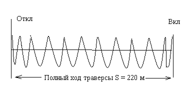
Picture 1
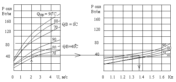
Figure 2 Figure 3
Variants II to 15. The resistance of the turn-to-turn insulation of the RBAS reactor was I MΩ at a temperature of 20°C. Determine if reactor drying is required. Give a schematic diagram of the measurement of this insulation.
Options 1C to 20. Draw up a test program for indoor 10 kV concrete reactors. The location of the phases of the reactors is made vertically (4, Fig. 3.14). Specify test equipment.
Options from 21 to 24. Draw up a test program for the KM2-0.38-75 capacitor. Give schemes, tests, indicate the devices used.
Options from 25 to 45. Using the nomograms in Fig. 2, Fig. 3, determine the possible overload (in amperes) of the wires of the overhead power line. The operating conditions and brand of the line wire are given in the table.
| Options | 25...27 | 28...30 | 31...33 | 34...36 | 37...39 | 40...42 | 43...45 |
| Wire brand | AS-25 | AS-25 | AS-35 | AS-35 | AS-50 | AS-50 | AS-70 |
| Air temperature? in, єС | 0 | 20 | 40 | 0 | 20 | 40 | 20 |
| Wire temperature?pr, ºС | 70 | 80 | 90 | 70 | 80 | 90 | 70 |
| Wind speed V,m/s | 1 | 1.5 | 2 | 1 | 2 | 3 | 2 |
The sequence for determining the multiplicity of permissible overload Kp is shown on the nomograms.
Options 46 to 54. Calculate the heating power P (kW) and data ( S, sq. mm; N- number of turns) of the magnetizing winding for drying the power transformer by the method of inductive losses. Perform the calculation for the transformer of the main substation from the course project on power supply. Bring the connection diagram of the magnetizing winding to the phases of the supply network, determine cos? .
Options from 55 to 64. According to the protocol of factory tests of the transformer R6o "" = 450 MΩ at a temperature? = 60 ° C. Bring these data to an installation temperature of 20°C.
Options from 65 to 74. According to the transformer factory test report, tg? 1 = 8.1% at a temperature of 60 ° C. Bring these data to an installation temperature of 20 ° C.
Options from 75 to 90. Make a list of works in electrical installations up to 1000 V of your enterprise (organization, workshop, department), which can be carried out by electrical personnel in the order of current operation. The list should be compiled in the form of an order by the chief power engineer.
Options and 90 to 95. Cables of the AAB brand 3x95 sq. mm in the amount of 50 pieces are laid in the tunnel, the load current is 100 A. Indicate the amount of heat dissipation per 1 m of the tunnel.
Options from 95 to 99. The thermal power emitted by APsPB cables 3x95 sq. mm (per 1 km of the laying length) is 50 kW, the average load current is 100A. Determine the laying method.
Options for task #2
It is required, on the basis of the scheme (Fig. 4), to draw up an order or fill out a switching form in accordance with the task. Both bus sections and transformers are in operation, the section switch is off.
| Options | Exercise |
| 00...05 | Cable line repair order W1 |
| 06...10 | Switching form for putting the W1 line into repair |
| 11...15 | Work order for the repair of transformer T5 |
| 16...20 | The form of switching to the output for repair T5 |
| 21...25 | Order for repair of line disconnector QS7 |
| 26...30 | Switching form for bringing the disconnector QS7 into repair |
| 31...35 | Work order for the repair of transformer T3 (TSN) |
| 36...40 | Form of switching to the output for repair T3 (TSN) |
| 41...45 | Work order for the repair of the input switch Q1 |
| 46...50 | Switching form for bringing the circuit breaker Q1 into repair |
| 51...55 | Order for the repair of the 1st section of tires |
| 56...60 | The form of switching to the output for repair of the 1st section of tires |
| 61...65 | Work order for the repair of transformer T1 GPP |
| 66...70 | The form of switching to the output for repair T1 GPP |
| 71...75 | Order for repair of voltage transformer TV2 |
| 76...80 | Switching form for withdrawal to repair TV2 |
| 81...85 | Work order for the repair of the sectional switch Q5 |
| 86...90 | Switching form for bringing the circuit breaker Q5 to repair |
| 91...95 | Order for the repair of the circuit breaker drive Q1 |
| 96...99 | Order for the repair of the QS5 disconnector of the TV4 transformer |
The disconnectors on both sides of the sectionalizer are normally closed. Both auxiliary transformers (TSN) are in operation, the sectional machine QF3 is normally disabled. 
Fig.4
LITERATURE
1. Rules for the installation of electrical installations (PUE). - M .: Energoatomizdat, 1986, - 648 p.
2. Rules for the technical operation of consumer electrical installations and safety regulations for the operation of consumer electrical installations (PTE and PTB) .-
4th ed.-M.: Energoatomizdat, 1986.- 392 p.
3. SNiP-111-33-76. Production and acceptance of works. Electrical devices.- M.: Stroyizdat, 1977.- 219 p.
4. Knyazevsky B.A., Trunkovsky L.E. Installation and operation of industrial electrical installations. - M: Higher school, 1984. - T75 p.
5. Fedorov A.A., Popov Yu.P. Operation of electrical equipment of industrial enterprises. -M.: Energoatomizdat, 1986.- 280 p.
6. Design of cable networks and wiring / Anastasiev P.I., Branzburg E.Z., Kolyada A.V. etc. - M.: Energy, 1980.-384 p.
7. Zabokritsky E.I., Kholodovsky B.A., Mitchenko A.I. Handbook on the adjustment of electrical installations and electrical automation. - Kyiv, Naukova Dumka, 1985. - 702 p.
8. Kinsht N.V., Gerasimova G.N., Kats M.A. Diagnostics of electrical circuits.- M.: Energoatomizdat, 1983.- 192 p.
7. GOST 11677-85. Power transformers. General specifications.-M: Izd.standartov, 1988-53s.
Abstract on the topic:
"Operation of electrical equipment in electrical networks".
Introduction
1 Measures aimed at improving the operational reliability of electrical equipment.
2 Organizational and technical measures to ensure the safety of work.
3 Operation of electrical equipment of switchgears.
4 Maintenance of complete switchgears.
5 Maintenance of disconnectors.
6 Maintenance of short circuiters and separators.
7 Monitoring the condition of current-carrying parts and contact connections.
8 Maintenance of consumer substations.
9 Operation of transformer oil.
Introduction
The development of production is based on modern technologies that widely use electrical energy. In this regard, the requirements for the reliability of power supply to agricultural facilities, the quality of electrical energy, its economical use and the rational use of material and labor resources in the design of power supply systems have increased.
Power supply, that is, the production, distribution and use of electricity in all sectors of the national economy and the life of the population, is one of the important factors of technological progress.
Industry, agriculture and transport are developing on the basis of electrification. The main feature of the production power supply is the need to supply energy to a small number of large-sized objects concentrated on the territory. The economic efficiency of the use of electricity largely depends on the problem of rational power supply of production. To solve these problems, technical policy solutions are applied: replacement of wires with SIPs, installation of transformers. Working without replacement for 40 years, the use of dry circuit breakers.
1. Measures aimed at improving the operational reliability of electrical equipment.
All switchgear equipment is operated in accordance with factory instructions, PTE, PUE and PTB rules and fire safety rules.
All data for planned, current and overhauls, as a rule, are entered into the operational documentation
In rural power supply, packaged switchgears for outdoor installation (KRUN) have become widespread. They are designed to operate at ambient temperatures from -40 to 40 °C. Switchgears (RU) 10 kV of distribution points (RP) and complete transformer substations 220-110-35 / 6-10 kV are assembled from KRUN cabinets. Switches VMG-10, VMP-10K, VMM-10 and others with manual, cargo, spring and electromagnetic drives are installed in the cabinets. For rural electrification, complete transformer substations (KTS) for a voltage of 6 ... 10 / 0.4 kV are widely used, consisting of transformers and blocks manufactured at the factory and delivered to the installation site assembled. The PTS equipment will be placed in a metal casing.
The industry manufactures PTS according to simplified schemes using, where possible, fuses, short circuits and separators. 35 kV circuit breakers are used only in the chain of feed-through (transit) lines of KTP 35/10 kV, in switchgear -35 kV. KTPB 110/35/6 - 10 kV.
In agricultural power grids, SK.TP 35/10 kV with a capacity of 630 ... 6300 kV * A are most widely used. manufactured according to the schemes of primary connections.
The main tasks in the operation of the reactor plant are: ensuring the compliance of the operating modes of the reactor plant and individual circuits with the technical characteristics of the equipment; supervision and maintenance of equipment; elimination in the shortest possible time of malfunctions that lead to an accident; timely preventive testing and repairs of electrical equipment
2. Organizational and technical measures to ensure the safety of work.
Preparation of workplaces for repair work.
If work is carried out without removing the voltage near live parts under voltage, measures are taken to prevent the approach of working persons to these live parts.
These activities include:
safe location of working persons in relation to energized live parts;
organization of continuous supervision of working personnel;
the use of basic and additional insulating protective equipment.
Works near and on current-carrying parts under voltage must be carried out along with them.
The person performing such work should be located so that the current-carrying parts are in front of him and only on one side, it is forbidden to work in a bent position.
Work on live parts under voltage is carried out using basic and additional protective equipment.
To prepare the workplace for work with partial or complete stress relief, the following technical measures must be performed in the sequence indicated below:
making the necessary shutdowns and taking measures to prevent the supply of voltage to the place of work due to erroneous or spontaneous switching on of switching equipment;
hanging posters: “Do not turn on - people are working” and, if necessary, installation of fences;
connection to the "ground", portable grounding. Checking the absence of voltage on current-carrying parts, which must be grounded;
overlay grounding (immediately after checking the absence of voltage), i.e. inclusion of grounding knives or, where they are absent, the imposition of portable grounding;
fencing the workplace and hanging posters: “Stop - high voltage”, “Do not climb in - it will kill”, “Work here”, “Climb here”. If necessary, fencing of the current-carrying parts remaining under voltage is carried out.
3. Operation of electrical equipment of switchgears.
One of the main tasks of switchgear operation is to maintain the necessary reserves in terms of throughput, dynamic, thermal stability and voltage level in the device as a whole and in its individual elements.
The frequency of inspections of switchgears. The frequency of inspection is set depending on the type of device, its purpose and form of service. Approximate inspection times are as follows: in switchgears serviced by shift personnel on duty at the substation itself or at home - daily. In unfavorable weather (sleet, fog, heavy and prolonged rain, ice, etc.), as well as after short circuits and when a signal appears and a ground fault occurs, additional inspections are carried out in the network. It is recommended to inspect the device once a week in the dark to identify possible corona discharges in places of insulation damage and local heating of current-carrying parts; in switchgears of substations with a voltage of 35 kV and above, which do not have permanent duty personnel, the inspection schedule is drawn up depending on the type of device (closed or open) and on the purpose of the substation. In this case, inspections are performed by the head of the substation group or the foreman at least once a month; transformer substations and switchgears of electric networks of 10 kV and below, which do not have on-duty personnel, are inspected at least once every six months. Unscheduled inspections at facilities without permanent duty personnel are carried out within the time limits established by local instructions, taking into account the short circuit power and the condition of the equipment. In all cases, regardless of the value of the interrupted short-circuit power, the circuit breaker is inspected after an unsuccessful AR cycle and the short circuit is disconnected.
All malfunctions noticed during inspections of switchgears are recorded in the operating log. Faults that interfere with normal operation must be rectified as soon as possible.
Serviceability of redundant switchgear elements (transformers, circuit breakers, busbars, etc.) must be regularly checked, including them under voltage within the time limits established by local regulations. Backup equipment must be ready to be switched on at any time without any prior preparation.
The frequency of cleaning dust and dirt from switchgears depends on local conditions and is set by the chief engineer of the enterprise.
Switch service. External inspections of oil circuit breakers without switching off are carried out taking into account local conditions, but at least once every six months, together with inspections of the switchgear. During inspections, they check: the condition of insulators, fasteners and busbar contacts; oil level and condition of oil indicators; absence of oil leakage from low-volume socket contacts or through gaskets of tank switches.
The oil level of the circuit breakers largely determines the reliability of their operation. It should not go beyond the oil pointer at ambient temperatures from -40 to 40 °C. An increased level of oil in the poles and a correspondingly reduced volume of air cushion above the oil lead to excessive pressure in the tank when the arc is extinguished, which can cause the destruction of the circuit breaker.
The decrease in oil volume also leads to the destruction of the circuit breaker. Reducing the volume of oil is especially dangerous in low-volume circuit breakers VMG-10, VMP-10. If the leak is significant and there is no oil in the sight glass, then the switch must be repaired and the oil replaced. In this case, the load current is interrupted by another switch or the load on this connection is reduced to zero.
Abnormal heating of the arcing contacts of low-volume circuit breakers causes darkening and rise of the oil level in the oil indicator glass, as well as a characteristic smell. If the temperature of the circuit breaker tank exceeds 70°C, the circuit breaker must be repaired.
In areas with a minimum temperature below 20 ° C, switches are equipped with automatic devices for heating oil in tanks.
At least once every three (six) months, it is recommended to check the circuit breaker drives. In the presence of auto-reclosing, it is advisable to carry out testing for shutdown from relay protection with shutdown from auto-reclosing. If it fails to operate, the switch must be repaired.
When externally inspecting air circuit breakers, attention is paid to its general condition, to the integrity of the insulators of arc chutes, separators, shunt resistors and capacitive voltage dividers, support columns and insulating stretch marks, as well as to the absence of contamination of the surface of the insulators. Using pressure gauges installed in the switch cabinet, check the air pressure in the circuit breaker tanks and its flow to the ventilation (for circuit breakers working with automatic reclosure, the pressure should be within 1.9 ... 2.1 MPa and for circuit breakers without automatic reclosure - 1, 6... 2.1 MPa). The circuit breaker control has an interlock that prevents the circuit breaker from operating when the air pressure drops below normal.
During the inspection, they also control the serviceability and correctness of the readings of devices signaling the on or off position of the switch. Pay attention to whether the dampers of the exhaust hoods of the arc chutes are closed securely. Visually check the integrity of the rubber gaskets in the joints of the insulators of the arc chutes, separators and their support columns. The degree of heating of the contact connections of tires and hardware connections is controlled.
During the operation of air circuit breakers 1-2 times a month, accumulated condensate is removed from the tanks. During the rainy season, the air supply for ventilation increases, when the ambient temperature drops below -5 ° C, the electric heating in the control cabinets and distribution cabinets is switched on. At least 2 times a year, the operability of the circuit breaker is checked by control tests for opening and closing. To prevent damage to the switches, 2 times a year (in spring and autumn) check and tighten the bolts of all sealing joints.
4. Maintenance of complete switchgears.
The operation of packaged switchgear (KRU) has its own characteristics due to the limited overall dimensions of the cells. To protect personnel from accidental contact with live parts under voltage, the switchgear is provided with a lock. In stationary switchgear, mesh doors are blocked, which are opened only after the circuit breaker and disconnectors are turned off. Draw-out switchgear has automatic shutters that block access to the compartment of fixed disconnecting contacts when the trolley is rolled out. In addition, there is an operational lock that protects personnel when performing erroneous operations. For example, rolling out the trolley into the test position is allowed by blocking only after the circuit breaker is turned off, and rolling out the trolley into the working position - when the circuit breaker and grounding knives are off. Observation of the equipment is carried out through viewing windows and mesh fences or inspection hatches closed with a protective mesh.
Inspections of switchgear without turning them off are carried out according to the schedule, but at least once a month. During inspections, they check the operation of lighting and heating networks and switchgear cabinets; condition of switches, drives, disconnectors, primary disconnecting contacts, interlock mechanisms; contamination and lack of visible damage to the insulators; condition of secondary switching circuits; operation of the switch control buttons.
Systematically, depending on local conditions, it is necessary to clean the insulation from dust and dirt, especially in outdoor switchgear.
When inspecting complete switchgears KRU and KRUN, it is necessary to pay attention to: the condition of the seals at the joints of the elements of metal structures; serviceability of equipment connection to the ground loop; availability of safety and fire fighting equipment; operation and serviceability of heating devices for KRUN cabinets; presence, sufficiency and normal color of oil in switches; condition of field connections; heating of live parts and devices; absence of extraneous noise and odors; serviceability of signaling, lighting and ventilation.
Simultaneously with the inspection, the correct position of the switching devices is checked. The equipment built into the switchgear and switchgear is inspected in accordance with the operating instructions. During operation of the switchgear, it is forbidden to unscrew the removable parts of the cabinet, lift and open the automatic shutters in the presence of voltage in those places to which they block access. In withdrawable-type switchgear cabinets for grounding the outlet lines using disconnectors built into the switchgear, you need to do the following: turn off the switch, roll out the trolley, check the absence of voltage on the lower disconnecting contacts, turn on the grounding switch, put the trolley in the test position.
The fuses in the auxiliary transformer cabinet can only be changed when the load is off. When carrying out work inside the compartment of the roll-out trolley, it is necessary to hang warning posters on the automatic shutter: “Do not turn it on! People are working”, “High voltage! Life threatening!"
Only operating personnel can roll out the trolley with the circuit breaker and install it in the working position. It is allowed to roll the trolley into the working position only when the earthing switch is in the off position.
5. Maintenance of disconnectors.
When adjusting the mechanical part of the three-pole disconnectors, the simultaneity of switching on the knives is checked. When adjusting the moment of contact and compression of the movable knives, change the length of the thrust or stroke of the limiters and thrust washers, or slightly move the insulator on the base or the sponge on the insulator. When fully turned on, the knife by 3 ... 5 mm should not reach the stop of the contact pad. The smallest pulling force of one knife and.) of the fixed contact should be 200 N for disconnectors for commemorative currents of 400 ... 600 A and 400 N for disconnectors for rated currents of 1000 ... 2000 A. The tightness of the contacts of the disconnector is controlled by the value of the DC resistance , which should be within the following limits: for RLND disconnectors (35 ... 220 kV) for a commemorative current of 600 A - 220 μOhm; for other types of disconnectors for all voltages with a rated current of 600 A 175 µOhm; 100 A - 120; 1500 ... 2000 A - 50 µOhm.
During operation, the contact surfaces of the disconnectors are lubricated with neutral vaseline with an admixture of graphite. The rubbing parts of the drive are covered with non-freezing grease. The condition of the disconnector insulators is assessed by the insulation resistance, voltage distribution on individual elements of the pin insulators, or by the results of testing the insulator with increased power frequency voltage.
Auxiliary contacts of the drive, intended for signaling and blocking the position of the disconnector, must be installed so that the signal to open the disconnector begins to act after the knife has passed 75% of the full travel, and the signal to turn on - not earlier than the moment the knife touches the fixed contacts.
6. Maintenance of short circuiters and separators.
Short circuiters are devices designed to artificially create a short circuit in cases where the current in case of damage in the transformer may not be sufficient to trigger the relay protection.
The short circuit type KZ-35 for voltage 35 kV is made in the form of two separate poles with a common drive. The short circuiter is switched on automatically by the SHIK drive when the relay protection is triggered, it is switched off manually.
Shutdown of power transformers without load, as well as automatic shutdown of damaged transformers, is carried out by separators. Separators OD-35 are RLND-35/600 type disconnectors equipped with two additional opening springs. Disconnection of the separator is carried out automatically or manually, inclusion - only manually using a removable handle.
At 35...110 kV connections with separators and disconnectors installed in series, the magnetizing current of transformers and capacitive currents of lines should be disconnected by separators.
Separators for 35 kV allow disconnecting the ground fault current up to 5 A. On average, for 10 km of a 35 kV overhead line, the charging current is 0.6 A and the ground fault current is 1 A.
Short circuiters and separators are inspected at least 2 times a year, as well as after emergency shutdowns. During inspections, special attention is paid to the condition of insulators, contacts, ground wire passed through the window of the current transformer. If traces of burning are found, the contacts are cleaned or replaced.
The duration of movement of the moving parts of the short-circuit device for a voltage of 35 and 110 kV from the impulse to the closing of the contacts should be no more than 0.4 s, and the separator from the impulse to the opening of the contacts, respectively, 0.5 and 0.7 s.
During the operation of short circuiters and separators, special attention should be paid to the most unreliable components: springs that are open or insufficiently protected from possible contamination and icing, swivel contact systems, as well as unprotected bearings protruding from the rear.
During the adjustment of the short circuiter and separator, attention is paid to the reliable operation of the separator blocking relay (BRO), which is designed for currents of 500 ... 800 A. Therefore, at short circuit currents. less than 500 A, the ground spike should be replaced with a wire and passed through the current transformer several times. If this is not done, the BRO relay will pull the armature indistinctly and thereby release the locking mechanism of the separator drive until the short-circuit current is turned off. Premature shutdown of separators is one of the reasons for their destruction.
The current repair of disconnecting devices, as well as checking their operation (testing) is carried out as necessary within the time limits established by the chief engineer of the enterprises. The scope of work for current repairs includes: external inspection, cleaning, lubrication of rubbing parts and measuring the resistance of contacts to direct current.
Unscheduled repairs are performed in case of detection of external defects, heating of contacts or poor condition of the insulation.
Adjustment of the short circuiter and separator consists in checking the operation of the drive for turning on and off, checking the position of the knives and the plant of the turning off spring of the drive with the blocking relay BRO, adjusting the stroke of the cores of the electromagnets and the relay.
7. Control of the state of current-carrying parts and contact connections.
The condition of current-carrying parts and contact connections of busbars and switchgear devices can be identified during inspections.
Control over the heating of detachable connections in closed switchgears is carried out using electrothermometers or thermal candles and thermal indicators.
The operation of an electrothermometer is based on the principle of temperature measurement using a thermistor glued to the outer surface of the sensor head and covered with copper foil.
The heating temperature of the contact joints is determined using a set of thermocouples with different melting points.
As thermal indicators, reversible films of repeated action are used, which change their color during prolonged heating. The thermal indicator must withstand, without being destroyed, at least 100 color changes during prolonged heating to a temperature of 110 °С
8. Maintenance of consumer substations.
The reliability of operation of consumer substations largely depends on the correct operation, which must be carried out in accordance with existing guidance and instructional materials. Operational and preventive maintenance work is carried out in order to prevent and eliminate possible damage and defects during operation.
The scope of these works includes systematic inspections, preventive measurements and checks. Scheduled examinations of the TP are performed during the daytime according to the approved schedule, but at least once every six months.
After emergency shutdowns of supply lines, when equipment is overloaded, a sharp change in weather and natural phenomena (sleet, ice, hurricane, etc.), extraordinary inspections are carried out. At least once a year, the engineering and technical staff perform control inspections of the TP. Usually they are combined with the acceptance of objects for work in winter conditions, with inspections of 10 or 0.4 kV overhead lines, etc.
To maintain the TP in a technically sound condition, scheduled preventive repairs are carried out, which make it possible to ensure their long-term, reliable and economical operation.
Inspections, repairs and preventive testing of equipment at 10 / 0.4 kV transformer substations are carried out mainly in a comprehensive manner in one time, without removing the voltage, and, if necessary, with partial or complete shutdown of the equipment.
When inspecting mast substations from the ground, they check the condition of fuses, disconnectors and their wires, insulators, fastening wires to the busbar, grounding slopes and contacts, fastening and mutual arrangement of high and low voltage wires, the state of the substation structure, the state of wood and reinforced concrete, the presence and condition of warning posters, as well as the integrity of locks and stairs. When inspecting substations of the KTP type, they additionally check the contamination of the surface of metal cases, cabinets, the tightness of the doors closing and the serviceability of their locks, the condition of the supporting foundations.
When inspecting the equipment of TS and PTS, it is necessary to pay attention to the following: at load breakers, disconnectors and their drives - the absence of traces of overlap and discharges on insulators and insulating rods; position of knives in fixed contacts; the external condition of the arcing knives and chambers at the circuit breaker; the correct position of the drive handles; the serviceability of the flexible connection between the knife and the inlet clamp at the RLND disconnector;
for fuses of the PK type, the fuses correspond to the parameters of the protected equipment, the integrity and serviceability of the cartridges, the correct location and fastening of the cartridges in fixed contacts, the condition and position of the fuse operation indicators;
for arresters - the absence of traces of an arc of overlap on the surface, the correct installation, the condition of the external spark gaps of the tubular arresters and the correct location of the exhaust gas zones;
for bushings, support and pin insulators - the absence of chips, cracks and traces of overlapping of the arc;
for the 10 kV switchgear busbar - the absence of traces of local heating of the contacts at the points of connection to the equipment and in the busbar connections, the condition of the color and fastening of the tires;
for cable devices - the condition of cable sleeves and funnels, the absence of mastic leaks, the integrity of the tips, the presence of markings, the grounding of sleeves and funnels, the condition of cable pits and passages through the steps;
for low voltage switchgear (0.4 kV) - the condition of the working contacts of the circuit breakers, fuses and automata, the absence of traces of soot, overheating and melting on them, the condition of current transformers, protection relays and arresters of the RVN-0.5 type, the integrity of the fuse links and their compliance with the parameters of consumers, the serviceability of the photorelay, the integrity of the seals and protective glasses on metering and measuring instruments, the condition of the contacts of the 0.4 kV busbar and its fastening.
To eliminate the malfunctions in the operation of the TP and PTS equipment noticed during the inspection, in cases that are urgent until the next current or major repairs, preventive selective repairs are carried out with the replacement of individual elements and parts. These works are performed by operational operational personnel.
9. Operation of transformer oil.
For reliable operation of oil-filled equipment, it depends on the condition of the transformer oil filled in the equipment.
Transformer oil in operation must be subjected to a reduced analysis and measurement of tg in accordance with the "Electrical Equipment Testing Standards" (SPO OPGRES, 1977) within the time limits indicated in Table. 4. and after the current repair of transformers and reactor.
Tab. 4. Sampling frequency of transformer oil
| Name | Rated voltage, kV | Oil sampling interval |
| Transformers for power units with a capacity of 180 MVA and more | 110 and above | At least once a year |
| Transformers of all capacities | 330 and above | Too |
| Other transformers and reactors | Up to 220 (inclusive) | At least once every 3 years |
| Oil-filled, non-hermetic bushings | 500 | During the first two years 2 times a year, then 1 time in 2 years |
| Too | 110-330 | During the first two years of operation once a year, then once every three years. |
| Oil-filled sealed bushings | 110-750 | Not checked |
| Tap changer contactors | ---- | Through a certain number of switching according to the instructions of the plant, but at least 1 time per year. |
Oil drying.
In energy systems, oil is dried in two ways: by sucking dry nitrogen or carbon dioxide through it at room temperature; a vacuum of 20 ... 30 kPa is created above the oil; spraying oil at room temperature and residual pressure of 2.5 ... 5.5 kPa. To speed up drying, the oil is heated to 40...50°C at a residual pressure of 8...13 kPa.
In the conditions of small repair enterprises, the oil is dried by heating or settling it at a temperature of 25 ... 35 ° C. Sludge is an extremely simple, cheap and oil-friendly method of drying. Its disadvantage is the long duration of the operation.
Drying the oil by heating is also easy, and the oil can be heated in a variety of ways, including in the transformer's own tank. But prolonged heating of the oil can lead to its deterioration.
Oil purification.
Under operating conditions, the oil is not only moistened, but also contaminated. Oil is purified from water and mechanical impurities by centrifugation and filtration.
Centrifugation separates water and impurities heavier than oil. The oil temperature should be 45...55°C. At low temperatures, the high viscosity of the oil prevents the separation of water and impurities, and when the temperature rises above 70 ° C, water is difficult to separate due to the onset of vaporization and increased solubility of water in the oil. In addition, at elevated temperatures, intensive aging of the oil occurs.
Filtration - forcing oil through a porous medium (cardboard, paper, fabric, a layer of bleaching material or silica gel) - is carried out using filter presses. Filter paper and cardboard not only trap impurities, but also absorb water.
Soft and loose cardboard has the highest hygroscopicity, but it does not retain sludge and coal well and releases a lot of fibers itself. The alternation of sheets of soft and hard cardboard in the filter press allows you to get a well-refined oil.
It is desirable to filter the oil at a temperature of 40…50 °C, since at a higher temperature the hygroscopicity of the cardboard decreases and the solubility of water in the oil increases. Contaminated cardboard can be rinsed in clean oil, dried and reused. It takes about 1 kg of cardboard to clean 1 ton of oil.
The filter press is usually switched on after the centrifuge to remove residual sludge and water. It provides almost the ultimate purification of oil from water and the highest dielectric strength of the oil. The advantages of the filter press include its ability to operate at normal temperatures, the absence of mixing of oil with air, and the ability to clean the oil from the smallest particles of coal. However, centrifuges are capable of purifying oils containing emulsions, while a filter press is not suitable for purifying such oils.
The centrifuge is used to purify oils in the tanks of operating transformers, but with strict observance of safety precautions. The use of silica gel or bleaching clays in filter presses as an additional filter medium significantly reduces the acid number of the oil.
List of used literature.
Pyastolov A.A. Eroshenko G.P. Operation of electrical equipment - M .: Agropromenergo, 1990 - 287 p.
Eroshenko G.P. Pyastolov A.A. Course and diploma design for the operation of electrical equipment - M .: Agropromizdat, 1988 - 160 p.
Rules for the installation of electrical installations - M .: Energoatomizdat, 1986 - 424 s
E.A. Konyukhova Power supply of objects. - M, 2001-320 p.
P.N. Listova The use of electrical energy in agricultural production, 1984
Similar abstracts:
The composition and brief technical characteristics of thicknessing machines, their purpose and scope. Requirements for electrical equipment, criteria for its selection. The principle of operation of electrical equipment and control systems. Calculation and selection of protection devices.
Design of a transformer substation
Development of a block diagram of a substation, selection of the number and power of power transformers. Calculation of the number of switchgear connections. Calculation of short-circuit currents, selection of current-carrying equipment and transformers, safety precautions.
The concept and principle of operation of the disconnector, its purpose and the interaction of its components. Areas of use and importance in the separator circuit. Advantages and disadvantages of oil switches. Varieties and distinctive features of drives, their designations.
Organization of operation of the power system to ensure uninterrupted supply of electricity to consumers. The main activities carried out during the maintenance of electrical equipment to improve the efficiency of its work, types of preventive work.
Technical characteristics of the substation "Severnaya". Characterization and repair of transformers, disconnectors, separators, short circuiters and switchgear. Electrical safety labor protection in the production and operation of electrical installations.
Drawing up a block diagram of a substation. Selection of the main equipment: the number and power of communication transformers, power flows at the substation. Calculation of the number of lines at the highest low voltage. Choice of switchgear scheme, needs scheme.
Transformers: general information, their classification and marking. Design features of transformers. Vacuum switches, their advantages and disadvantages. The principle of operation of separators and short circuiters. Disconnectors for indoor installation.
Study of oil switches. Circuit breakers in layout with arc chutes at the bottom and with chambers located at the top. General view of the low-oil generator circuit breaker. The use of artificial blowing of the contact system and supply tires.
Automatic air circuit breakers, their operation and maintenance. Low voltage circuit breakers. Maintenance and operation of low voltage circuit breakers. Generator high-voltage air switches.
Disconnectors as devices designed to turn on and off sections of electrical circuits under voltage in the absence of load current. The difference between separators and short circuiters. Structural difference between the individual types of disconnectors.
Purpose, composition, equipment and block diagram of a traction substation. Selection of equipment, calculation of transformer protection parameters. Gas, differential and overcurrent protection of the step-down transformer. Overload, blower protection.
Consideration of the concept, purpose and classification of power voltage transformers, the conditions for their inclusion in parallel operation. Description of the design and principle of operation of rod, armored, toroidal and oil-cooled transducers.
The operation of electrical equipment of any facility, including a private house, no matter how large it may be, must be carried out in accordance with the requirements of the Rules for the Use of Electricity, the Rules for the Technical Operation of Consumer Electrical Installations and the Safety Rules for the Operation of Consumer Electrical Installations. These rules are mandatory for all consumers of electricity, regardless of the departmental affiliation of the house. Responsibility for the technical condition and safe operation of electrical installations, electrical wiring, electrical equipment (instruments, apparatus, etc.) of private property rests with its owner.
Particular attention should be paid to electrical safety, as well as the constant readiness of all types of fire-fighting devices, if any. When accepting electrical equipment for operation, it is necessary to obtain executive project documentation and documents on acceptance and the possibility of connecting the electrical installations of the facility to the power grids of the area from the developer.
For private property, it is mandatory to complete a power supply project (with a total installed power of more than 10 kW), which should include the following materials:
- scheme of external and internal power supply;
- scheme of internal wiring (type of wires and method of laying);
- scheme of input devices;
- calculation of electrical loads;
- selection of circuit breakers and fuse links;
- grounding or zeroing (if necessary);
- installation of a residual current device at the input (if necessary - at the point of connection of the object to the mains);
- electricity metering.
For private property with a total installed capacity of less than 10 kW, a lightweight design drawing can be made, which should reflect:
- a diagram of external and internal power supply indicating the types and settings of protective devices, sections and brands of wires, rated currents, electricity meters, connection to the supply network;
- situational plan for the location of electrical equipment, laying cables, wires, grounding and neutralizing conductors;
- specification of electrical equipment of products and materials;
- explanations, instructions, notes (if necessary).
At objects located territorially in one place, as a rule, installation of only one electric meter should be provided. For garden and country houses in front of the meter to turn it off, it is allowed to install a switching device or a fuse.
The electrical safety of people, both inside the facility and outside, must be ensured by a set of electrical protective technical measures, including the use of residual current devices, both at the point of connection of electrical networks and inside the facility, re-grounding the neutral wire at the air input, neutralizing electrical receivers, using double insulation input to the object. For grounding, a separate conductor with a cross section equal to the phase should be used, laid from the inlet cabinet (box). This conductor is connected to the neutral conductor of the supply network in front of the meter. The use of a working neutral conductor for this purpose is prohibited.
The connection of electrical installations to the electrical network is carried out by the personnel of the energy supply organization that issued the technical specifications. The private owner-consumer must ensure the serviceability of his electrical installations. He is not allowed to connect an electrical load in excess of that permitted in the specifications, as well as increase the current ratings of fuses and other protective devices.
The relationship of this consumer with energy supply organizations is determined by the "Rules for the use of electrical energy" and the contract for the use of electrical energy concluded by the consumer with the energy supply organization.
The owner of a private house must provide:
- maintenance of electrical equipment and networks in working condition and its operation in accordance with the requirements of modern regulatory and technical documentation;
- reliability of electrical installations and the safety of their maintenance.
If the owner is interested in the smooth operation of his electrical equipment, he must provide for the availability of spare parts and materials.
The electricity supplied to the house and to the site is necessary for electric lighting, electric heating, electric heating of food, powering radio and other equipment, signaling, driving electric pumps and power tools (drills, saws, etc.). It should be remembered that the use of electricity for thermal purposes requires a special permit from the Energy Supervision authorities. Its distribution according to these needs is made from the main input-distribution device, which should be installed near the input of the supply distribution line coming from the transformer substation.
If there is a personal plot, then power supply is also provided for auxiliary structures and premises. It is carried out using insulated wires of overhead lines or cables of internal wiring through an electric meter installed in the house.
The device of electrical installations, their operation and repair must comply with the requirements of the system of labor safety standards and safety regulations. Protective equipment, devices and tools used in the maintenance of electrical installations must comply with the current regulatory and technical documents on labor protection. The owner or the personnel employed by him must be guided by the instructions for labor protection.
Electrical installations must be provided with the necessary protective equipment according to the established minimum standards.
The owner of the house must have technical documentation, in accordance with which his electrical installations are approved for operation:
- master plan with applied buildings, structures and underground electrical communications;
- approved executive project documentation (drawings, explanatory notes, etc.) with all subsequent changes;
- acts of acceptance of hidden works, testing and adjustment of electrical equipment, electrical installations;
- technical passports of the main electrical equipment;
- certificates of conformity for materials and equipment.
For the competent operation of electrical installations, it is necessary to know how electricity is supplied to a building or object.
If the input is three-phase, then 3 linear wires and 1 neutral or zero are connected to the house, which is both a working (N) and protective (PE) conductor.
In modern power supply schemes, instead of one neutral wire, two can be supplied, one of which is protective (PE, and its color is green-yellow), and the other is working (N - blue color).
Most often, in a transformer substation, the neutral point of the transformer, from which a neutral wire is supplied to all sections, is “deafly” grounded, that is, connected to the ground, and the potential of this neutral wire corresponds to the zero potential of the earth (why the wire is sometimes called zero). The remaining three wires are at such potentials that the voltage between any two wires (voltage is the potential difference) is usually 380 V, and the voltage between any of the line wires and the neutral wire is 220 V in this case. If the neutral wire is grounded, then the voltage between any of the line wires and ground or grounded building structure, overhead line poles, etc. is also 220 V, which should never be forgotten. The same voltage can also appear between the ground and any current-carrying part of electrical equipment connected to these linear wires by electrical wiring wires, socket terminals, switches, etc.
Currently, in the vast majority of cases, input to an individual house is carried out according to a single-phase scheme. In this case, one of the linear wires and always neutral (zero) is connected to each house in the village. As already noted, at present, there are zero protective (PE) and zero working (N) conductors. They can be combined into one or approach the consumer separately with two wires. Thus, either three or two wires can be connected to the house.
The entry into the building is carried out with an insulated wire or cable with a non-combustible sheath. The cross section, brands of wires and cables are selected taking into account their purpose and conditions of use in accordance with the "Electrical Installation Rules". It should be noted that these Rules are currently undergoing changes, and it is necessary to use their most recent edition, in particular, 1999.
The device for re-grounding the neutral wire at the input to the object is mandatory for all three-phase inputs; the need for such a single-phase input is determined in each specific case by the project (in particular, this is necessary for an overhead power line). Re-grounding of the neutral wire at the input is carried out using a grounding conductor consisting of one or better several steel rods with a diameter of at least 12 mm or pieces of angle steel with a wall thickness of at least 4 mm, providing the required resistance depending on the soil resistivity, which is determined by the project.
In the places where the input wires are connected to the branch wires, contact connections are made only with the help of clamps. Connection of input wires to branch wires in the span is prohibited. This may result in electric shock to people and animals.
Electrical inputs to the premises are carried out through the walls in insulated pipes in such a way that water cannot accumulate in the passage and penetrate into the premises. For the purpose of fire safety, the passages for inputs in walls made of combustible materials are made in steel pipes.
When operating overhead lines, the shortest distance from the wires entering the facility, as well as the wires of the internal electrical wiring to the ground surface, must be at least 2.75 m.
The cross section of wires of branches and inputs to buildings must be at least, mm²:
It is necessary to monitor the sag of the wires, to prevent their excessive swinging, as well as touching the wires with tree branches, climbing plants and other vegetation.
The operation of the input distribution devices is carried out in accordance with the established operational responsibility boundary between the energy supply organization and the given facility, where maintenance is carried out by the owner or hired personnel. The boundary of operational responsibility is determined by the Act of delimitation of operational responsibility with the organization operating the power grids of the given area.
All incoming and outgoing lines, as well as protective, switching and measuring equipment, must have the necessary inscriptions and signs.
Protective (and other) equipment must strictly comply with the design parameters.
The premises of the input distribution devices must meet the requirements of ventilation, humidity and temperature and always have appropriate protective equipment for safety. Based on the "Rules for the operation of electrical installations of consumers", measurements of insulation resistance, grounding resistance, checking the operation of circuit breakers and other protection devices should be systematically carried out. Installation and operation of electrical energy metering devices are carried out in accordance with the requirements of Energosbyt, the "Electrical Installation Rules" and the instructions of manufacturers. All means of measuring and accounting for electrical energy, as well as information-measuring systems must be in good condition and ready for work. All electrical energy metering devices are subject to mandatory state or departmental verification.
The state check of settlement means of accounting for electric energy and exemplary measuring instruments is carried out by the energy supply organization within the time limits established by state standards, as well as after the repair of these means.
The owner of a private house is responsible for the safety and cleanliness of the external elements of electrical energy meters. He must immediately report all violations in their work to the energy supply organization. Opening of electrical measuring instruments is allowed only to the personnel of this organization. Replacement and verification of settlement meters is also carried out by personnel. All defects or cases of failure in the operation of electric energy meters must be immediately reported to the energy supply organization.
The power supply organization must seal:
- settlement counters;
- switching or protective device when installed in front of the meter.
When commissioning the grounding devices of electrical installations, the installation organization, in addition to the documentation, must submit acceptance test reports.
When operating and repairing grounding devices, it must be borne in mind that each part of the electrical installation to be grounded (grounded) must be connected to the grounding (grounding) network using a separate conductor. Consistent connection to the grounding or zero protective conductor of the grounded parts of the electrical installation is prohibited. Grounding and neutral protective conductors must be coated to prevent corrosion. Openly laid steel grounding conductors must be black in color. To determine the technical condition of the grounding device, the following should be periodically carried out by a specialized organization:
- measurement of the resistance of the grounding device and selective testing with the opening of the soil of the grounding elements located in the ground;
- checking the condition of the circuits between grounding conductors and grounded elements, as well as the connections of natural grounding conductors with a grounding device.
For everyone switchboards there should be inscriptions and indicators of incoming and outgoing lines, settings of automatic switches, fuses and other necessary information. A switchboard is a device where electricity is supplied from the input-distribution device using distribution lines and where, with the help of protective devices (fuses, circuit breakers), group lines outgoing from the switchboard are protected, feeding directly to electrical receivers (lamps, household and technological equipment, etc.). .P.).
During the operation and maintenance of switchboards, it is necessary to carefully monitor the condition of the protective equipment. Fuses must be calibrated. In no case should you use wire "bugs" instead of standard fusible links! Circuit breakers must strictly comply with the design parameters and, in accordance with the "Rules for the operation of electrical installations of consumers", be tested for operation. There is a high risk of fire when using uncalibrated or faulty protective equipment. In control panels, it is necessary to check the compliance of the contact solution of contactors, relays and magnetic starters with passport data. At knife switches and switches, during the current repair, the contact surfaces are brought to a normal state. They are cleaned of dirt, oxides, soot.
During the operation of the distribution and group networks of the building, special attention should be paid to hidden wiring. It is necessary to monitor the insulation of the wires. Measurements of insulation resistance should be carried out systematically in accordance with the "Rules for the operation of consumer electrical installations". Moreover, insulation resistance measurements should be carried out by an organization that has a license. It is necessary to pay attention to the reliability of fastening of the installation equipment: switches, sockets, etc., to the tightness of the contacts for connecting lines to the distribution and installation equipment and to their temperature.
When operating a cable line with a voltage of up to 1000 V, in addition to the above documentation, technical documentation must be drawn up and transferred to the customer (executive design of the cable line, made on a scale of 1:200, executive drawing of the route indicating the installation locations of the couplings; acts of hidden work indicating intersections and convergence of cables with all underground utilities; certificates for the installation of cable boxes). Upon acceptance into operation of a newly constructed cable line, tests must be carried out in accordance with the requirements of the "Electrical Installation Rules" and the "Rules for the Operation of Consumer Electrical Installations".
When operating unarmoured hose-coated cables, special attention must be paid to the condition of the hoses. Cables with hoses that have through gusts, scuffs and cracks must be replaced. Openly laid cables, as well as all cable joints, must be provided with tags indicating the brand, voltage, section, number or name of the line; and on the tags of the couplings - the number of the coupling and the date of installation. The tags must be resistant to environmental influences and located along the length of the line every 50 m on openly laid cables, at turns in the route and at the places where cables pass through fire-resistant partitions and ceilings (on both sides). Inspections of the cable line are carried out in the following terms: cable routes laid in the ground - at least 1 time in 3 months; cable routes laid along the walls of buildings - at least 1 time in 6 months. If signs of destruction of metal sheaths due to electrical, soil or chemical corrosion are found on the cable line, urgent measures should be taken to prevent them. During excavation of cable routes or earthworks, appropriate supervision of the safety of cables must be ensured. Digging trenches and pits at the locations of cables and underground structures should be done with extreme caution, and at a depth of 0.4 m or more - only with shovels (in winter with soil heating). At the same time, it is necessary to ensure that a layer of soil with a thickness of at least 0.3 m remains from the surface of the heated layer to the cables. The thawed soil should be discarded with shovels. The use of crowbars and similar tools is strictly prohibited. Excavation by earthmoving machines at a distance closer than 1 m from the cable, as well as the use of jackhammers, crowbars and picks to loosen the soil above the cables to a depth of more than 0.3 m at a normal cable laying depth (0.7 m) is prohibited. The use of impact and vibro-submersible mechanisms is allowed at a distance of at least 5 m from the cables. Before starting work, a control opening of the route should be carried out to clarify the location of the cables and the depth of their laying under the supervision of the electrical personnel of the organization operating the cable lines.
Electric lighting plays a large role in the interior and exterior design of a custom home, and also provides comfort that is impossible in the absence or insufficiency of natural light. The power, shape, color of lamps and fixtures, as well as their location are very important. Lighting in all rooms and the landscape of a private house must comply with the norm, if this does not contradict the desire of the owner. Luminaires must be only factory-made and comply with the requirements of state standards and specifications. Emergency lighting fixtures (if provided) must differ from them in signs or colors. When the main power source is disconnected, the emergency lighting network should automatically turn on from an independent power source (battery, etc.). The emergency lighting network must be made without socket outlets. In switchboards of the lighting network, all circuit breakers must have inscriptions with the name of the connection, allowable value current settings, and on the fuses - with an indication of the current value of the fuse-link. The use of uncalibrated fuse-links in all types of fuses is prohibited. A stock of calibrated fusible links, lamps and lamps of all voltages of a given lighting network is desirable.
Portable hand-held lamps must be powered by a mains voltage of not more than 42 V, and in case of increased risk of electric shock - not more than 12 V.
Appliance plugs for 12 or 42 V must not be plugged into sockets for 127 or 220 V. All sockets must be labeled with the rated voltage.
The use of fluorescent lamps and DRL lamps (high-pressure mercury gas discharge lamps) that are not mounted on rigid supports for portable lighting is prohibited.
Installation and cleaning of lamps of the electric lighting network, replacement of burned-out lamps and calibrated fuses, repair and inspection of the electric lighting network must be carried out by specialists.
With a suspension height of luminaires up to 5 m, their maintenance from ladders and step-ladders is allowed. If the luminaires are located at a higher height, their maintenance from stationary bridges (scaffolding) and mobile devices is allowed, subject to the obligatory observance of safety measures, with stress relief. Out of service fluorescent lamps, DRL lamps and other sources containing mercury should be kept packed in a special room. They must be periodically taken out for destruction and decontamination to the places designated for this.
Checking the condition of stationary equipment and electrical wiring for emergency and working lighting, testing and measuring the insulation resistance of wires, cables and grounding devices should be carried out when the electric lighting network is put into operation, and then according to the appropriate schedule. Defects found during inspection and inspection must be eliminated as soon as possible.
Electric motors, ballasts, instrumentation, protection devices, as well as all electrical and auxiliary equipment must comply with the requirements of the "Electrical Installation Rules" and other applicable regulatory and technical documents. Electric motors and the mechanisms driven by them must be marked with arrows indicating the direction of rotation. On electric motors, their switching devices, ballasts, fuses, etc. there must be inscriptions with the name of the unit and (or) mechanism to which they refer. Fusible fuse links must be calibrated and have the stamp of the manufacturer or the department responsible for the electrical facilities of the enterprise, indicating the rated current of the setting. The use of uncalibrated inserts is prohibited. In the event of an emergency shutdown of the electric motor by the protection device, it should be switched on again only after the examination, control measurements of the insulation resistance and checking the serviceability of the protective devices.
The electric motor must be immediately disconnected from the network in the following cases:
- in case of accidents with people;
- when smoke or fire appears from the electric motor, as well as from its ballasts;
- in case of breakage of the drive mechanism, the appearance of an abnormal knock;
- with a sharp increase in the vibration of the bearings of the unit;
- when the bearings are heated above the allowable temperature set in the manufacturer's instructions.
Currently, a large number of foreign equipment is used in private homes. In this regard, it must be remembered that when using imported electrical equipment, special attention should be paid to the relevant factory instructions, which should not contradict Russian norms and rules.